In this post we see how to build an enhanced and efficient car headlight lamp using Pirhana LEDs.
A car LED headlight is a powerful lamp built using high efficiency LED arrays, which creates extremely powerful headlight lamp for the car, along with a very high efficiency in terms power consumption.
Using 4-pin Pirhana LEDs
You might be pretty familiar with the ordinary two-pin, 5mm white LEDs, which are by no means “ordinary” and produce lights at reasonably high intensities.
However when it comes to 4-pin LEDs, the 2-pin types stand no where near it. Include just 50 of them in a group, and you are well producing lights that may be more dazzling than conventional car headlight intensities.
Here I have explained how to implement 4-pin LEDs in automobiles for making their headlights more power efficient and more powerful.
In fact the application may not be restricted to just car headlights, you might want to use them for other applications also, like as a LED tube light in your home, that can result in a lot of saving in your electrical utility bills.
Before we proceed with the proposed circuit of efficient high power LED head light design details, let’s first analyze the important specs of this interesting light emitting device.
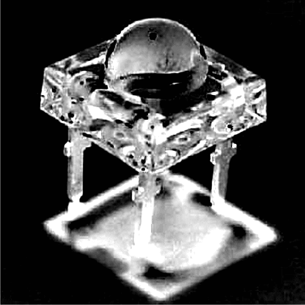
A 4-pin super bright piranha LED might look complex at the first appearance, but a careful look will assure you that it’s as easy to understand as a two pin type.
Though the device includes 4 pin outs, two on each side are actually shorted internally, and therefore technically it has just two outputs, one anode and the other cathode quite like our ordinary two pin LEDs.
However a four pin arrangement is made to suit it’s size and for assisting firm PCB mounting, the square extra large shape of a 4-pin LED is designed to introduce some special features in it, attributing the qualities of generating extravagant light emissions to them.
Main Specifications of 4-pin super flux LED
The following text provides some of the important specs related to 4-pin LEDs:
- Safe operating temperature – 25 to 80degree Celsius
- Typical operating voltage – 3.5 volts,
- Maximum operating voltage – not to exceed 4 volts.
- Normal continuous operating current – 20 mA,
- Peak instantaneous current – up to 100 mA Viewing angle – 50 degrees.
Efficient Car Headlights Using 4-Pin Super Flux Piranha LEDs
The DIAGRAM illustrates a simple application circuit using 48 high intensity 4-pin LEDs for automobile headlights.
Since the operating forward voltage of the LED type is around 3.5, three of them accommodates in each channel, in series.
The series are further connected in parallel for making the total number up to 48. Voltage is derived from the car battery via the dashboard switch.
Preferably the LEDs may be arranged in circles for uniform distribution of light across the whole headlight enclosure.
Circuit Diagram
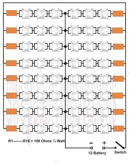
The PCB used must be a glass epoxy type, double sided; the hind side copper of the laminate is not etched and is used as a heatsink for absorbing heat from the LEDs and dissipating it in the air.
Using a Single 10 watt LED
If you thing the above discussed method is too laborious, then you can opt for a single 10 watt LED for enhancing your car headlights with low consumption LED lights.
The following image shows how a 10 watt LED actually looks like:
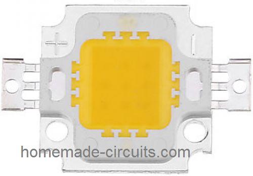
The two fins across the sides are the two terminals which will connect with the 12V supply from the car.
Not to mention each of these LEDs on the headlights must incorporate a current control circuit in order to ensure a safe and an optimal illumination, as shown below.
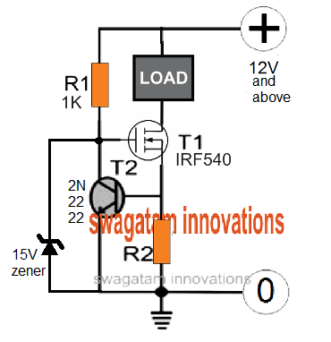
R2 is the current sensing resistor and could be calculated as discussed in the below sections.
I have already posted a couple of LED current limiter circuits which you can study through the following links, and implement those in between the LED lamp and the 2V supply from the battery:
Current Limiter using Transistors
Any of the above concepts can be applied for protecting the 10 watt car headlight LED lamps from over current or a thermal runaway situation.
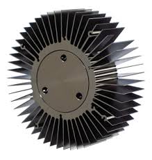
However make sure the LEDs are mounted over well calculated heatsink, which could be a round finned type as shown below, this may be mounted behind the headlight box:
Using other Forms of LEDs
If you wish to use any other form of LED having different specification than the above, you can definitely do that by calculating the resistor values appropriately by using the formula:
Resistor = Supply voltage - Total Forward V spec of the LED series / LED current
R = (Vsupply - Vf) / ILED
Where:
- R = Current Limiter Resistor value
- Vsupply = Supply voltage
- Vf = Total Forward Voltage specification of the LED series
- ILED = Maximum Safe LED current
For example suppose you would want to make a headlight lamp using 1 watt, 3.3V 350mA LEDs, and your supply voltage is 12V from your car battery, in that case the above formula could be calculated in the following manner:
Consider each string has 3 LEDs in series:
R = 12 - (3.3 x 3) / 0.35 = 6 Ohm
o it is 6 ohms resistor that you would need to put in series with each of the LED strings having 3 LEDs in series.
And what about the resistor wattage or the power?
For evaluating wattage simply multiply the difference between the supply and LED total voltage drop with the LEd current, therefore for the above case we get:
Power = 12 - (3.3 x 3) x 0.35 = 3.46 watts, the nearest safer value is 4 watts.
In this way you can use any desired LED for your car headlight by suitably calculating the series current limiting resistor.
Adding a PWM Intensity Control
One added advantage of a LED based car headlight is that it can be facilitated with a PWM intensity control, which will not only enable the user to vary the intensity of the car headlight as desired, but also save precious battery power.
The following image shows a simple IC 555 PWM control that can be used for the mentioned purpose very easily and effectively.
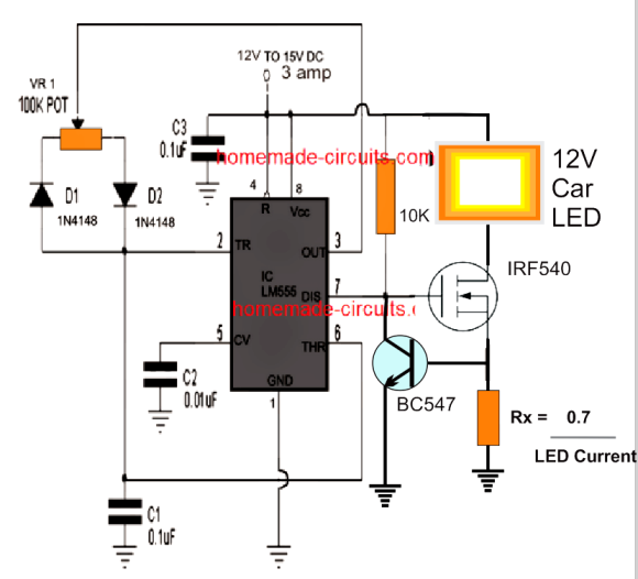
The above design also features a current controller stage which ensures that the LED can never consume more that the rated current and thus work safely under all circumstances. The resistor Rx must be appropriately calculated depending on the maximum current rating of the LED.
The MOSFET must be mounted on a suitable heatsink to ensure optimal performance from the LED.
Caution: When high wattage LEDs are used always make sure to add a specialized current limiter stage in between the supply input and the LED module, as already explained in the previous paragraphs of this articles.


Questions & Answers
thank you so much for introducing this circuit your reference to this circuit in me made a idea so that i can have more authority and options over atiny MICRO IC,
i have repeatedly wanted to use a MOSFET as a switch or key , like the transistors but i was not successful and i feel they do not behave like transistors i want to use it as a strong switch instead of a relay ,
please suggest a circuit for this thank you so much in advance for your humble help
You can use IC 555 in SMD form to make the design miniature. MOSFets will work like a switch when you apply 12V across its gate/source, but it will work with only DC loads
Hello sir,
I need a circuit of rechargeable lamp using LEDs up to 60pcs. The input will be 220V and the battery voltage will be 4VDC and I will like it to be transformerless power supply.
If one wants to increase the number of LEDs, how can one go about it? Thank you sir.
Hello Thiter, you can try the 2) surge free design from this article:
https://www.homemade-circuits.com/how-to-make-efficient-led-emergency/
Hi Swagatam,
I want to build a led top light for aquarium using 4 pin leds the circuit mentioned above can it be used off a 12v DC adapter?
Hi Suhail, yes you can build it for the mentioned purpose. You can add or deduct the LED strings as per your preference for increasing or decreasing the illumination
Thanks
Please provide a circuit diagram If I use straw hat 5mm Leds .in a string of day 200.
Driving it thru a 12v DC adapter.
Thank you.
The circuit design will be the same, just the resistors values will change to 450 ohms…1/4 watt, but whether 200 numbers can be accommodated or not will depend on the current consumption of your adapter
Hello Swagatam,
I can't see the attached pics and circuit diagram. Following error is shown: HTTP Error 404 – File or Directory not found
I wish to make DRL and tail light using superflux led's in place of regular 3 or 5mm led's.
Can you pls help me out in making a drl & tail light for my bike using your circuit diagrams and layout. I am a novice in electronics with but love doing DIY stuff.
Thanks
Hi Gaurav, I am not having any difficulty in seeing the diagram from here…you can open this link to see it separately
3.bp.blogspot.com/-ACwhhtZz-L4/Tu2YkUeuO2I/AAAAAAAAAXA/jq3lf3vNzY8/s640/4-pin+LED.png
for a DRL you can follow the following concept and apply it suitably for your specific application
https://www.homemade-circuits.com/2013/07/making-led-halogen-lamp-for-motorbike.html
if you have any doubts please feel free to ask
Hello sir I don't know about piranha leds as I have seen it have 4 pins so how to solder it in series can u explain pls
Hello basit, see the diagram in the above article, you can see two leads on each side of the LEDs are shorted and connected to each other in series, you can do it in this manner.
Hi all,
I build a replica Iron Man ARC reactor last year for Halloween.
https://drive.google.com/file/d/0B32qJakASDM4OENsSzJBMTZXeG8/view?usp=sharing
I used 17 LEDs used here in this project, directly connected to a 3.7v LiPo cell. Unfortunately the cell runs at ~4.1v at full charge. This caused several of the LEDs to fail over the course of the evening.
I want to replace the LEDs and build in a regulator or a resistor to stop this from happening again.
I'm fine with the mechanics, but not entirely 100% on what I'd need, or how to place it regarding the electronics. Can anyone assist?
If you have used 5mm LEDs, you could connect 50 ohm 1/4 watt resistors separately with each individual LEDs. in the array.
Hello Swagatam,
Really nice and useful projects.
Can you upload a bigger circuit diagram. The one present doesn't show other compopnents very well.
….sorry it's not responding to a click, I'll make it bigger in a moment.
Thanks,
please click on the diagram, it will enlarge in a new window with the all the details magnified.