• Skip to main content
  • Skip to primary sidebar

Homemade Circuit Projects

Need circuit help? Post them in the comments! I've answered over 50,000!

Blog | Categories | About | Contact | Calculators-online
You are here: Home / Automobile Electronics / Car Head Lamp Fader Circuit (Breathing Effect Generator)

Car Head Lamp Fader Circuit (Breathing Effect Generator)

Last Updated on August 15, 2019 by Swagatam 6 Comments

The proposed circuit of a modified car head lamp fader, "breather" circuit generates a slow flashing effect over the head lamps every time the lamps are switched OFF. The "breathing effect" continues for a certain predetermined period after which the process automatically shuts off. The circuit was requested by Mr. Ray.

Table of Contents
  • Technical Specifications
  • The Design

Technical Specifications

I just wanted to say that what you do here in you blog is wonderful. I just came across them in Google looking for a chasing light circuit.

Love it and will be using it. I do have a question about this timer circuit though. Could I have this hooked up to my headlight switch and when I turn off the switch it starts the count?

I would like to add this to a breathing light circuit so when I turn off my lights, the head and tail lights fade in and out for a set amount of time.

Would this be the circuit I need for the timing aspect? Thank you in advance, and there is no rush.

Ray.

The Design

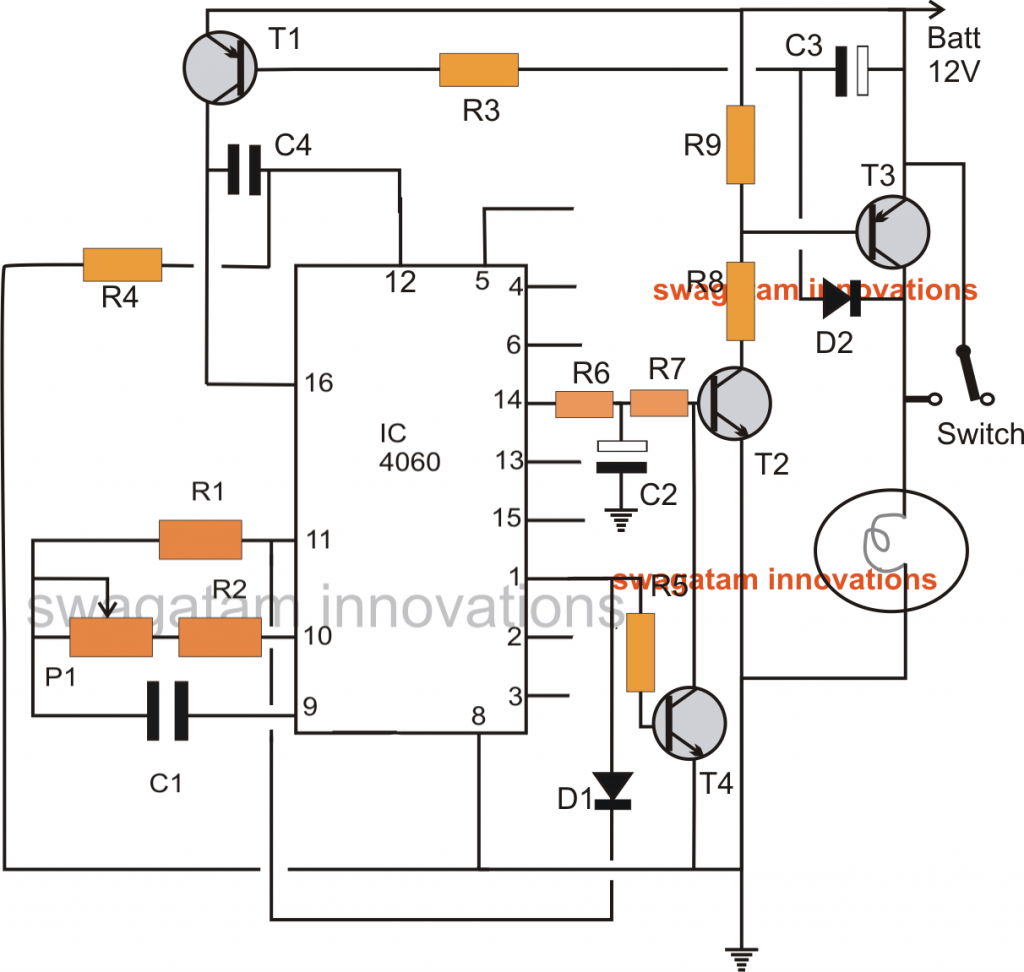
The proposed car head lamp fader circuit can be witnessed in the the below given diagram, I have explained about it functioning details:

As long as the main switch stays in switched ON position D2 is held reversed biased, so that T1 is unable to conduct and thus the entire circuit stays switched OFF.

In an event the main head light is switched OFF D2 instantly receives a negative potential via the head lamp filaments which switches ON T1.

T1 now provides the required supply to the IC 4060, which instantly initiates counting process.

C4 makes sure that the IC begins the timing from zero and not randomly when power is switched ON.

C3 makes sure that T1 keeps conducting even while D2 gets reversed biased in response to T3 flashing.

Pin#2 starts counting, while pin#14 begins oscillating at some predetermined rate. The time periods at pin#2 and pin#14 can be optimized by appropriately setting the preset P1.

The oscillating frequency at pin#14 triggers T2 in the corresponding manner which in turn switches T3, and the head lamp, with the required blinking/fading effect.

The slow rise and fall or the "breathing effect" over the lamps is generated together with the help of R6, R7, and C2. The values of these components should be selected and optimized through experimentation for getting an interesting fading effect.

In the meantime as pin#14 generates the pulses, pin#2 counts and as soon as the set time elapses, it becomes high.

The high at pin#2 latches the IC via D1 and also disables T2 from conducting. The situation shuts off the head lamps completely.

The circuit remains locked in this position until the main switch is  yet again reset manually to repeat the process.

carheadlightmodifiedcircuit

Parts list for the above car head lamp fader, "breathing effect" generator circuit

  • R1, R3, R4 = 100K
  • R2, R9,R5 = 10K
  • R6, R7 = 470 OHMS
  • R8 = 50 OHMS, 2 WATT (ARBITRARY)
  • C1, C4 = 0.1uF
  • C2 = any value between 220uF and 1000uF
  • C3 = 100uF/25V
  • D1, D2 = 1N4148
  • P1 = 100K PRESET
  • T4 = BC547
  • T1 = BC557
  • T2 = 2N2222 OR 8050
  • T3 = TIP36

You'll also like:

  • 1.  Build a Homemade GSM Car Security System
  • 2.  How to Make Powerful Car Headlights Using LEDs
  • 3.  Customizing Car Side Marker Lights to Flashing Side Markers
  • 4.  Automotive Trailer Lights Interface Circuit
  • 5.  High Voltage, High Current DC Regulator Circuit
  • 6.  Car Door Close Optimizer Circuit

About Swagatam

I am an electronics engineer with over 15 years of hands-on experience. I am passionate about inventing, designing electronic circuits and PCBs, and helping hobbyists bring their projects to life. That is why I founded homemade-circuits.com, a website where I share innovative circuit ideas and tutorials. Have a circuit related question? Leave a comment.... I guarantee a reply!

Previous Post: « Timer Controlled Exhaust Fan Circuit
Next Post: Cree XLamp XM-L LED Datasheet »

Reader Interactions

Comments

  1. José Rodrigues says

    August 13, 2019 at 5:07 pm

    I really enjoyed this project and maybe will do it to apply to my car, but I have some doubts that I would like to clarify.
    Resistance R8 has among relatives arbitrary, which means by that.
    What is the reference of capacitor C4 and transistor T1.

    Thanks
    José Rodrigues

    Reply
    • Swagatam says

      August 13, 2019 at 8:47 pm

      Thanks very much!, R8 will depend on the lamp current, and can be adjusted for optimum illumination.

      Sorry did not understand what you meant by…”What is the reference of capacitor C4 and transistor T1…” please elaborate

      Reply
      • José Rodrigues says

        August 15, 2019 at 12:47 am

        Now that I’ve looked at the list again, it’s not C4 but C2 that doesn’t have the value in the list.
        The T1 I see now on the list. Probably saw it wrong, I apologize for the mistake.
        Just missing then is the C2.

        Thanks
        José Rodrigues

        Reply
        • Swagatam says

          August 15, 2019 at 10:56 am

          No problem jose, I have updated the value of C2 in the parts list

          Reply
  2. Dr Ankit says

    October 26, 2015 at 2:38 pm

    Dear Sir,
    Can IC 4060 be substituted with IC 4066 (not only for this circuit but for any circuit)
    Thanks

    Reply
    • Swagatam says

      October 27, 2015 at 4:59 am

      Dear Ankit, both the ICs are entirely different, so cannot be exchanged

      Reply

Need Help? Please Leave a Comment! We value your input—Kindly keep it relevant to the above topic! Cancel reply

Your email address will not be published. Required fields are marked *

Primary Sidebar

Subscribe to New Circuit Ideas

Categories

  • Arduino Projects (87)
  • Audio and Amplifier Projects (132)
  • Automation Projects (17)
  • Automobile Electronics (101)
  • Battery Charger Circuits (83)
  • Datasheets and Components (104)
  • Electronics Theory (143)
  • Free Energy (37)
  • Games and Sports Projects (11)
  • Grid and 3-Phase (19)
  • Health related Projects (25)
  • Home Electrical Circuits (12)
  • Indicator Circuits (14)
  • Inverter Circuits (87)
  • Lamps and Lights (142)
  • Meters and Testers (69)
  • Mini Projects (46)
  • Motor Controller (64)
  • Oscillator Circuits (27)
  • Pets and Pests (15)
  • Power Supply Circuits (108)
  • Remote Control Circuits (50)
  • Security and Alarm (64)
  • Sensors and Detectors (101)
  • Solar Controller Circuits (59)
  • Temperature Controllers (42)
  • Timer and Delay Relay (49)
  • Transmitter Circuits (29)
  • Voltage Control and Protection (37)
  • Water Controller (36)

Calculators

  • Battery Back up Time Calculator
  • Capacitance Reactance Calculator
  • IC 555 Astable Calculator
  • IC 555 Monostable Calculator
  • Inductance Calculator
  • LC Resonance Calculator
  • LM317, LM338, LM396 Calculator
  • Ohm’s Law Calculator
  • Phase Angle Phase Shift Calculator
  • Power Factor (PF) Calculator
  • Reactance Calculator
  • Transistor Astable Calculator
  • Transistor base Resistor Calculator
  • Voltage Divider Calculator
  • Wire Current Calculator
  • Zener Diode Calculator
  • Filter Capacitor Calculator
  • Buck Converter Calculator
  • Boost Converter Calculator
  • Solar Panel, Inverter, Battery Calculator
  • Wire Current Calculator
  • SMPS Transformer Calculator
  • IC SG3525, SG3524 Calculator
  • Inverter LC Filter Calculator

People Also Search

555 Circuits | 741 Circuits | LM324 Circuits | LM338 Circuits | 4017 Circuits | Ultrasonic Projects | SMPS Projects | Christmas Projects | MOSFETs | Radio Circuits | Laser Circuits | PIR Projects |

Recent Comments

  • Swagatam on Real MPPT Solar Charger Circuit Using Arduino, LCD, and Manual/Auto Switch
  • Obaidullah Khan on Real MPPT Solar Charger Circuit Using Arduino, LCD, and Manual/Auto Switch
  • Swagatam on 2 Compact 12V 2 Amp SMPS Circuit for LED Driver
  • Alan Bishop on AC Motor Speed Controller Circuits using Back EMF
  • Swagatam on Real MPPT Solar Charger Circuit Using Arduino, LCD, and Manual/Auto Switch

Company

  • Privacy Policy
  • Cookie Policy
  • About Me
  • Contact
  • Disclaimer
  • Copyright
  • Videos
  • Sitemap

Social Profiles

  • Twitter
  • YouTube
  • Instagram
  • Pinterest
  • My Facebook-Page
  • Quora
  • Stack Exchange
  • Linkedin
  • © 2025 · Swagatam Innovations