In this post I have explained how to build a battery deep discharge protection circuit which can be used for protecting any type of battery from over discharge through a connected load.
Normally, we are mostly worried about battery getting over charged, and forget about a situation where the battery can get over discharged by the load. Although, overcharging a battery may be detrimental to a battery health and appropriate measures must be incorporated, an over discharge or a deep discharge can be also equally dangerous for a battery's health.
In the following paragraphs I will elucidate a very simple design for shutting off the battery to the load, as soon as the battery voltage has reached the critical deep discharge state.
The circuit is fully solid-state and uses only transistors for the switching, thus eliminating the need of bulky relays.
Circuit Specifications
The idea was actually requested by one of the dedicated readers of this blog, Mr. Saurav, as I have explained below:
Looking for some ideas/help/suggestions. I have installed a 2.2 kw off grid solar system, using loom solar panels, excide battery and excide solar inverter. The inverter has this pre-setup priority, first solar, then grid, last battery. I have disconnected the mains supply to the inverter, so for me it is solar then battery. To this overall setup, I have added an ACCL with grid as secondary.
So in the evening, whenever there is no solar and the battery is out of charge, it falls back to grid power.
This setup has one problem. ACCL switches to mains power at night, when the battery is completely drained out or deeply discharged and that's what I don't want.
I want to turn off the battery power, when the battery has 20% remaining power or the battery is at a certain voltage. That way battery life can be better.
Is this something doable? Do we have something readily available for this? Or do we need to build something for this?
The Design
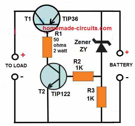
The circuit design for the proposed battery deep discharge protection circuit can be witnessed in the following diagram:
As can be seen, the circuit has a very components, and its working can be understood through the following points:
There are a couple of power transistors coupled with each other where, the base of the TIP36 transistor forms the collector load of the TIP122 transistors.
The base of TIP122 is biased through a resistor/zener diode network, where the zener diode ZY determines the cut off voltage for the TIP122.
The zener diode voltage is selected such that it matches the critical low voltage value of the battery, or any value at which the draining of the battery by the load is required to be stopped.
As long as the battery voltage stays above the zener voltage, or the voltage at which the cut-off needs to happen, the zener diode keeps conducting which in turn keeps the TIP122 in the conducting mode.
With TIP122 conducting the TIP36 gets the required base current, and it also conducts and allows the battery current to pass to the load.
However, the moment the battery voltages reaches or drops below the zener voltage which is also the deep discharge voltage level, causes the zener diode to stop conducting.
When the zener diode stops conducting, the TIP122 base voltage is cut off and it switches OFF.
With TIP122 now switched OFF, the TIP36 is unable to get its base bias current, and it also switches OFF turning off the battery current to the load.
The procedure effectively prevents the battery from further draining and depleting below its deep discharge level.
The indicated load can be any specified load, such as an inverter, a motor, an LED lamp etc.
How to Select the Zener Diode
The zener diode decides at what voltage the battery needs to cut off from the load. Therefore, the zener voltage must be approximately equal to the battery voltage at which the cut off needs to happen.
For example, if for a 12 V battery, the deep discharge cut off value is 10 V, then the zener diode ZY value can be also selected to be 10 V / 1/2 watt.
Using a MOSFET
The indicated TIP36 can supply a maximum current of 10 amps to the load. For higher current, the TIP36 could be replaced with a P-Channel MOSFET such as the MTP50P03HDL, which is rated to handle at least 30 amp current.
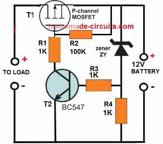
When a MOSFET is used in place of the BJT TIP36, the 50 ohms resistor can be replaced with a 1K resistor or a 10K resistor, and the TIP122 can be replaced with a BC547.
Adding a Battery Charger with a Single Transistor
The above discussed concepts are used to handle the over discharge situation of a connected battery. However, if you want the above circuit to also have its own battery charger, then the following circuit can be used for the process effectively.
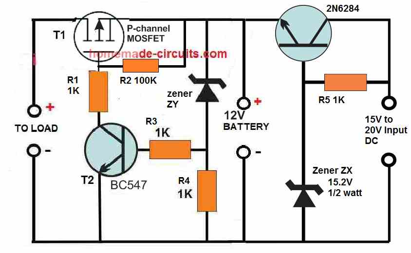
Here we can see a transistor stage on the right side of the design, which is configured as an emitter follower. The transistor is a 2N6284, which is rated to provide at least 10 amp current to the battery, which means it is able to charge even a 100 Ah battery efficiently.
Since the transistor is a Darlington transistor and configured as an emitter follower, the voltage at its emitter will always lag behind its base voltage by 1 V or 1.2 V.
The zener diode must be cautiously selected so that it compensates the emitter drop of 1.2 V by providing a potential at the base which may be 1.2 V higher than the required emitter voltage.
Since the circuit is designed to charge a 12 V battery, the full charge voltage at the emitter of this transistor must be around 14.1 V. This implies that the base voltage of the transistor must be 1.2 V higher than the emitter, which amounts to a value of around 15.2 V to 15.3 V.
This is exactly why the zener must be rated at the above specified voltage for generating a constant 14. 1 V at the emitter side and across the connected 12 V battery.
While charging the battery when the battery terminal voltage reaches the 14.1 V value, it reverse biases the emitter of the 2N6284, which shuts down the conduction of the transistor, thereby stopping any further charging of the battery, and the battery is safeguarded from over charging.
The above shown circuit thus implements a 2 in 1 procedure of preventing battery over deep discharge and also over charging through the use a just a few transistors, and still is able to control a battery that may be as big as a 12 V 100 Ah battery.
Deep Discharge Protection with more Accuracy
In the above 2 BJT concepts, cutoff drifts with load, so when load changes then behavior also shifts. Different transistor gives different cutoff point, since no two devices behave exactly same. Temperature sensitive too, so heat comes then things move. Due to this cutoff feels soft, kind of mushy, not clean break.
However in the following 3 BJT version, cut-off point stays stable, even when conditions change. Behavior is repeatable, so you build again and it works same. Disconnect of load is sharp, clear on and off. Works same with small load or large load, no deviations...
How it Works
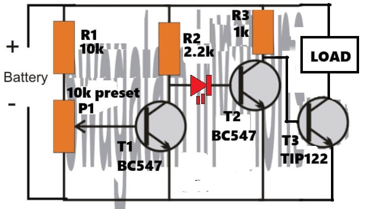
This circuit keeps monitoring the battery voltage all the time. If the battery voltage is healthy then the LOAD stays ON and keeps working.
But when battery voltage drops below a preset level then the circuit disconnects the LOAD.
This helps prevent deep discharge, which otherwise damages batteries, especially lead-acid and Li-ion packs without BMS, so that damage part is avoided.
Blocks In The Circuit
The whole circuit can be seen as four simple functional blocks working together.
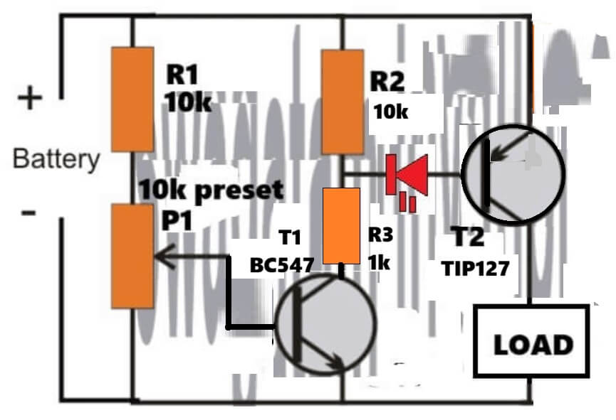
- First is the voltage sensing network using R1 and P1.
- Then comes the comparator transistor T1 (BC547).
- After that there is the switching or driver stage using T2 (BC547).
- Finally the power switching is handled by T3 (TIP122), which actually controls the LOAD.
Voltage Sensing (R1 + P1)
R1 (10k) and P1 (10k preset) form a voltage divider connected to the battery. The wiper of P1 feeds the base of T1 directly.
So as battery voltage rises or falls, the voltage at T1 base also changes along with it. P1 sets the cutoff voltage, so here you decide when the LOAD should disconnect, like at 10.8 V or 11.0 V and similar values. This part is basically the adjustment control of the whole circuit.
T1 – The Voltage Detector (BC547)
T1 works like a simple comparator here. When battery voltage is HIGH, the voltage at T1 base becomes greater than about 0.6 V, then T1 turns ON and its collector voltage drops toward ground.
When battery voltage becomes LOW, then base voltage of T1 falls below about 0.6 V, then T1 turns OFF and its collector voltage rises through R2.
So T1 converts the battery condition into logic levels, giving a LOW signal when battery is OK and a HIGH signal when battery voltage is low.
T2 – Logic Inverter + Buffer (BC547)
R2 (2.2k) pulls the base of T2 HIGH when T1 is OFF.
When the battery is OK, T1 stays ON, its collector is LOW, so T2 base is LOW and T2 remains OFF. But when battery voltage drops, T1 turns OFF, its collector goes HIGH via R2, then T2 base becomes HIGH and T2 turns ON.
In this way T2 flips the logic and also provides stronger drive for the power transistor.
LED Indicator Role
That LED is doing two jobs at the same time, it gives visual indication because when the battery voltage falls below the preset level, then the LED lights up, and because of that it acts as a LOW BATTERY indicator.
When the battery is OK the LED stays OFF, but when the battery goes LOW then the LED turns ON, simple and very useful in real-world use.
At the same time the LED also works as a reference voltage and level shift. A red LED drops about 1.6 V – 1.8 V, which is much higher and more stable than a normal diode, so because of this T2 does not turn ON immediately. It turns ON only when T1 fully releases the node, and that helps improve cutoff accuracy and noise immunity. In short, the LED creates a clean threshold for T2 switching.
Now looking at how the LED works inside this circuit, when the battery voltage is OK then T1 is ON and the node feeding the LED is pulled LOW, so the LED stays reverse biased and OFF. Because of that T2 remains OFF and TIP122 stays ON, therefore the LOAD remains powered.
But when the battery voltage drops below the preset level, then T1 turns OFF and the node rises via R2. At that point the LED becomes forward biased and lights up, so now the base of T2 gets proper bias and T2 turns ON. Once T2 turns ON, the TIP122 base is pulled LOW and therefore the LOAD disconnects.
T3, Power Switch (TIP122)
TIP122 is a Darlington transistor so it has very high gain and can handle high current loads easily. When battery voltage is OK, T2 stays OFF, so the base of TIP122 gets drive and TIP122 turns ON, allowing the LOAD to remain powered.
When battery voltage becomes LOW, then T2 turns ON and pulls the base of TIP122 LOW, so TIP122 turns OFF and the LOAD gets disconnected. This is the stage where the actual battery protection happens.
A Potential Drawback
One drawback of the above circuit is that if the battery voltage is allowed to drop continuously even after the load is turned off, at one stage the battery will become so low, that T2 will no longer be able to remain ON causing T3 to switch ON, which will now cause the load to be switched ON again, and then the battery might be forced to further deplete until it gets completely exhausted.
To avoid the above issue, the last circuit above can be simplified using just two BJTs, as shown below:




Questions & Answers
Hello, I consider your site a valuable source of consultations especially in power electronics with the topics of three-phase inverters, I have long searched for a three-phase signal generator out of phase at 120 degrees and here you have explained it, I would like to see a generator 180 degree phase shifted 3 phase square wave with operational amplifiers to control the speed of a 12 volt 3 phase motor using a full wave bridge with mosfet.
Thank you in advance for your cooperation
Respectful regards
Hello thank you, I am glad you liked this site, however you have asked your question under unrelated article. The above article is about battery deep discharge…for further doubts plese ask your questions in the following article:
https://www.homemade-circuits.com/three-phase-signal-generator-circuit/
My lecturer, Swagatam, can I use ths deep discharge and over charging circuit in the modified sine wave inverter u referred to me as the the best in my workshop as auto cut off in my battery charger?
Thanks Morris, yes you can definitely use the last circuit with the modified sine wave inverter circuit
Hello Swagatam, which charger circuit do I use to charge solar battery in my shop? Which one is the best
Hello Morris, please provide the specifications of your battery, I will try to help!
Am using 100ah solar battery. Advise me which one to use with the modified sine wave inverter
You can use the last circuit from the above article, it will work for 100Ah battery also. Make sure to use a 10 amp charger as the supply source
Thanks sir. But do have any best 10amp charger?
The 10 amp will depend on the transformer or the SMPS power supply used as the input…which you can buy and connect externally.
Refer me to your best charger I can use to with my free maintenance battery 100ah sir. Am creating a backup in my shop, therefore I seek your guidance.
You can refer to the following two articles, and select any one of them, all are good ideas:
Lead Acid Battery Charger Circuits
Op amp Battery Charger Circuit with Auto Cut Off
Please sir does it mean, that the output (to load) can be connected to output of an inverter? (I.e A.c )
Godspower, I did not understand your question?
Sir I mean from the first circuit diagram ( To Load), will it be connected to the inverter output A.c positive and negative?
Godspower, yes the load can be an inverter also, to the inverter battery points.
Swagatam,
I am having trouble getting this circuit to work. I am using the p-channel mosfet (IRF4905) and the BC547 with the values you have shown. I am trying to get a 9v battery to be cut off when the value drops below 5 volts.
Actually, I am using a 1N4732A, or a 4.7V zener. When the voltage drops below the 4.7, the output just follows the declining voltage and doesn’t shut off as expected. Please advise.
Chris, The cut off will not be sharp since it is being controlled by a single BC547 transistor, rather this will be a gradual choking. You can try adding a 1N4148 diode in series with the emitter of the BC547 and check if that improves the condition.
Thanks, Swagatam.
I recently found another of your articles, which used an LM358 , and that seems to work very well; I can fine tune the cutoff point.
Thanks and I love your stuff.
It’s very informative.
That’s great Chris, Glad the circuit fulfilled your requirement. Please keep up the good work!
How can alter the charging current of the charger please
It will need to be controlled from the power supply side only.
Swagatam,
I need to make a discharge circuit, that when pressing a switch is discharged to a limit, what calculations should I take into account and can I do it by means of resistors that absorb the current?
Hello Mariana, I think you can try the following concept. It will discharge your battery at constant current until reaches a particular voltage value.
https://www.homemade-circuits.com/precise-battery-capacity-tester-circuit-backup-time-tester/
Hi mr swagatam..
Great circuit for deep discharge & cut it off.. In your last circuit, what should to modify for 18650?. Is it just modify both diodes?
Thanks for advise.please keep up the great works..thanks
Thank you MP3, glad you liked the circuit.
Yes it is only the zener diodes whose values will need to be modified as per your battery specs. Rest everything can be as is.
Greetings
Sir,
Regarding yor first circuit .For my low power of about 1ampere only can i replace tip36 with which transistor can substitute?(easly available in market)Morover need to change the value and watts of50 ohm resistor?
Expecting your valuable reply
Regards,
Sison
From Kerala…INDIA With❤❤❤❤
Hi Sison, for 1 amp load you can replace the TIP36 with TIP32 transistor or a TIP127 transistor. The 50 ohm can be replaced with a 1K 1 watt transistor
Hello Swagatam, I have 15amps transformer which I want to use to charge a 200ah battery. Now i want to use this deep discharge circuit to help save the battery. I tried the second circuit auto cut off using lm358 in your article but I do find it difficult to set the two preset coz it’s not working for me. Can this deep discharge circuit help as an alternative to switch off the the circuit whn battery full and does it connect again automatically to recharge again? Pliz help.
Hello Morris, the above deep discharge does not have an auto cut off but in the last circuit, the transistor 2N6284 will automatically stop charging the battery once it reaches the full charge level as set by the zener diode value. Because when the battery voltage reaches the same value as the emitter voltage of the transistor then no current can flow from the transistor emitter to the battery.
Yes Swagatam, so once the the last circuit cut off upon reaching the charging level. Whn the battery starts draining to a lower level then it will reconnect to initiate charging again? Thanks
Yes definitely, as soon as the battery terminal voltage drops below the existing emitter voltage of the transistor, the current will start flowing from the emitter towards the battery positive, and the battery will start getting charged again.
But how do you see, if 2n6284 is a darlington transistor which is rated 100v 20amps. Can I use it to deliver the right charging current for 200ah battery? Secondly, if not do I go for another darlington transistor with at least 30amps or I use pieces and connect in parallel? Am using a rectified transformer with 15amps’ please guide.
You can replace the transistor with 2N5683. Or you can use two TIP35 in parallel. But make sure to convert each of these transistors into a Darlington by configuring a 2N2222 with their bases. After constructing the circuit you must adjust the zener value such that the emitter of the transistor produces a 14.3V output. You can further confirm the output by connecting a 1K load across the BJT emitter and ground. Also make sure to mount both the power transistors close to each other over a single common heatsink.
On this last diagram where can I connect my PV if am using solar as I can see it has two inputs help me understand the circuit
On the last diagram you can connect the PV across the points indicated as “15V to 20V input DC”
Hi, Greetings…!!!
Dear Swagatham,
Regarding the first circuit with tip122 and tip36…its workas fine.but when after the deep discharge terminal voltage rise immediately so it starts the chattering of output load.How can us make a little time delay to start the output again after once detected deep discharge.please help.
Hi Sison, I having difficulty understanding how and when the battery terminals will go high after the deep discharge? Do you mean when the battery is cut off from load?
Anyway you can try adding a 100uF capacitor across the base emitter of TIP122 and check the response.
Hi Swagatam,
Sorry, I missed a line from my previous post.
I would like to protect a 12V 14Ah lead acid battery from being overcharged or deep discharged.
The battery supplies LED garden lighting and is charge by an 18V 6W solar panel
Having looked at the components I have available, I wondered if the following would work?
From Circuit 1 ‘over discharge’
Replacing TI (TIP36) with DARLINGTON 2N6388G
Replacing T2 (BC547) with NPN 2N2222
Zener ZY = 12V ½ watt
Adding the ‘overcharge protection’ from Circuit 3
Replacing T3 (2N6284) with NPN 2N6388G
Thanks for the help,
Peter
Hi Peter,
2N6388 is an NPN so it cannot be replaced with TIP36 which is a PNP transistor.
The remaining selections are OK.
Hi Swagatam,
Thanks for the swift reply, I’m making a mess of this.
What I should have said:
I would like to protect a 12V 14Ah lead acid battery from being overcharged or deep discharged.
The battery supplies LED garden lighting and is charge by an 18V 6W solar panel
Having looked at the components I have available, I wondered if the following would work?
From Circuit 1 ‘over discharge’ duel transistor arrangement
Replacing TI (TIP36) with TIP46C
Replacing T2 (TIP122) with NPN 2N2222
Zener ZY = 10V ½ watt, R1 =50 ohm
Adding the ‘overcharge protection’ from Circuit 3
Replacing T3 (2N6284) with NPN 2N6388G
No problem Peter,
Now it looks much better, and you can go ahead with it, except a few things.
I am not so sure about TIP46C since I could not find any data regarding it online. If it is a PNP and equivalent to TIP36 then it may be fine.
Also using a 10V zener would mean the battery draining down to 10V which may not be a good thing for the battery. Better to use a 11V zener instead.
The remaining aspects look OK to me.
Good day,I’m very interested in what you doing,and I’m able to learn more. When I got questions wil you be able to help me?
I’m a electronic technician and I love my work.
Best Regards
Friedell
Thank you, you can ask your questions, if it possible for me I will try to solve them for you.
Hello and many thanks again, I got here from https://www.homemade-circuits.com/gel-cell-battery-charger-circuit-constant-current-constant-voltage/ and I like this circuit, based on a transistor logic instead of one based on an opamp comparator, and since here the main value is obtained with a zener diode, now about replace it with a TL431 reference?
Many thanks and best regards
That’s great Andrea, all the best to you, hope it works for you.
Hello sir,
Thank you for such a simple circuit for deep discharge protection as well as charging with auto-cutoff. I want to use this circuit as a UPS system connected to my raspberry pi (I will step down 12v to 5v at the pi’s input). I have a question regarding the charging part of this circuit. I will set the charging voltage to 13.5v and charging current to about 650mA. Can I keep the charger connected to the 12v battery continuously, as a float charger? If I understand correctly, as the battery voltage will reach 13.5v, no current will flow from the emittor to the battery and this will act like an auto-cutoff mechanism, protecting the battery from overcharging. Is my understanding wrong in any manner?
Thanks again
Thank you Sandeep!
Yes, you can keep the charger permanently connected with the battery if you set the maximum charging voltage to 13.5V or even 14 V for a 12V battery.
That’s correct, once the battery terminal voltage reaches 13.5V it will automatically stop consuming the charging current any further.
However, please note that since the above circuit designs use only one transistor for the cut off, the process of cut off will be quite slow and gradual, meaning the cut off will not be sharp at a specific point, rather will happen within a span of around 1.5 V.
Thank you for the quick reply sir. Understood about the gradual cutoff. Also, can I add 2 or 3 diodes like 1N4007 so that the charging voltage drops from 14.5v to around 13.5v ? If this is not the correct way or a very efficient way to drop the voltage in the above charger circuit, can you please suggest any alternative method?
You are welcome Sandeep! yes, you can add 2 or 3 diodes to adjust the output voltage to the desired level. Just make sure the diodes are adequately rated according to the charging current. I think 1N5402 diodes will be quite enough for handling 650 ma current. 1N4007 may start getting hot at 650 mA.
hello and thank you again
please tell me what is the R4 used for ? can we just omit it ?
R4 is required, it creates a voltage divider with R3.
Hi Mr ingenious engineer. Straight forward post. Really you make complicated things so simple, which is a sign of mastery of your knowledge. Thanks.
My question: Can I use this circuit with a 3,7 battery diy Bank? If yes, what is the value of the zener diodes for the Charging Section (5,1v ?) and the Discharge Protection section ?
Thank you Abega,
You can use the above circuits for charging 3.7V battery but then a MOSFET cannot be used in the circuit, you will have use only BJTs.
In the last circuit you can replace the mosfet with a TIP127 transistor. The 2N6284 can be replaced with TIP122.
Zener ZY can be a 3.3 V zener diode, and ZX can be a 5.1V zener. However check and confirm the output at the emitter of the charger transistor, it should be around 4.1V
Thanks very much sir for the knowledge you pass to everyone
Thanks so much Kefson, Glad you found this site useful…
In the battery discharge article can I use 2N3055 transistor in place of the stated 2N6284 because I cannot get here
Yes, you can use 2N3055, but make sure to calculate and adjust the R5 (1K) base resistor to the correct value so the transistors is able to deliver the required amount of current to the battery.
Dear Swagatam!
I would like to use your circuit idea but I ‘m afraid that’s not suitable for my application.
So, I have to ask you about.
I need to use a battery over discharged protection, to an alarm panel were the battery is standing by.
The battery is all the time is under charge and when there is no AC, starts supplying 12V the system.
What do you suggest?
Hi George,
The deep discharge protector circuit explained above is created exactly for the kind of application that you have mentioned, so definitely you can use it and it will fulfill the purpose.
Is there any pcb design to print for the first circuit?
Sorry, I have not designed the PCB for this circuit, you may have to contact a professional PCB manufacturer for this.
Hi Swagatam,
I use a 2500W inverter with a 120Ah battery to supply me with 220VAC when we have a power outage.
I want to protect the battery from discharging below 11.9V. When the power is restored I then have a smart charger which will charge the battery and prevent over charging.
Can you suggest which one of your circuit’s will be sufficient to perform this task.
Regards
Jan
Hi Jan,
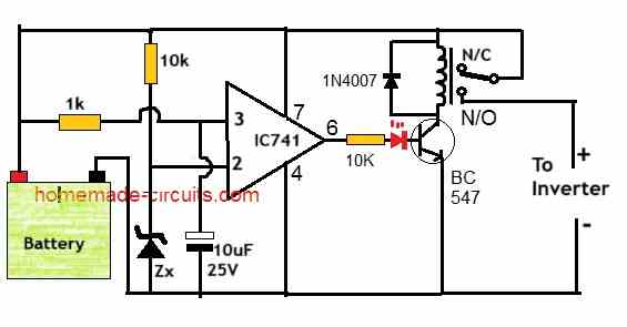
Since your battery is a high current battery, it will require a relay based cut off.
You can use the following circuit for implementing the battery over-discharge cut off:
Thank you Swagatam I appreciate your help.
You are welcome Jan!
Hi Swagatam,
Is it possible that I can use a SCR instead of a relay?
I have some heavy duty SCR’s in stock namely FS08E 647A. I have tried to get the specs. on this but was unsuccessful. I assume the 647A is the amp rating of this SCR?
If this is feasible could you please help me with the cct required.
My load is an 2000W inverter with a 120Ah 12V battery. If my calculation is correct then Max amp draw is 160A?
Your help will be much appreciated.
Regards
Jan
Hi Jan,
Unfortunately SCRs cannot be used with a DC supply, because once switched ON the SCR will get latched permanently, so it cannot be turned off simply by turning off the gate supply.
However, you can use a MOSFET instead.
Let me know your opinion on this.
Hi Swagatam, Can you please explain the purpose of the LED on the base of the BC547.
Regards
Jan
Hi Jan, when the LED is ON it indicates that the relay is ON and the inverter is getting normal battery power.
When the battery is over discharged, the LED shuts down indicating that the relay is OFF and the battery is charging.
LED ON simply means the battery is not yet fully discharged.
Additionally, the LED also blocks the leakage voltage from the opamp output and prevents the transistor/relay from false switching.
Hi Swagatam, I have completed this cct and it works very well. Just one small problem. The relay chatters slightly when switching at 10V. How can I prevent this?
Regards
Jan
Thank you Jan, Glad it is working.
To prevent relay chattering you can simply add a 100uF/25V capacitor across the base/ground of the BC547 relay driver transistor.
Hi Swagatam,
Please assist me with the voltage of the Zener diode I should use. I am using a 12V diode at the moment, but according to a battery chart it must be a 12.9V diode. Is this correct?
Regards
Jan
Hi Jan,
The zener value should be exactly equal to the desired low battery cut-off level.
So 12V zener is the correct value that you have chosen.
With this zener value, the relay will cut-off as soon as the battery voltage drops below 12V.
The best way to confirm the cut-off level is by replacing the battery with a variable power supply input.
Sir I have 12V 9 A Battery. I want to cutt off load when battery goes 11.9V. I don’t need a charger option just reason of I already have it. Suggest me a low voltage Cutt off circuit. Please
Hi Jobayer,
you can simply use the first circuit from the above article by adjusting the zener diode value to 11.9V.
Hiw can one connect battery bank proper wiring to ensure maximum charging
Hello Mr Swagatam, thank you very much for this circuit. Exactly what I was looking. My question is regarding the voltage from the panel, what will happen when it reaches 18 volts? does that mean that the voltage to be received by the battery will be 17.8v? or do I need a voltage regulator to limit the voltage to just 16v?
Thanks
Thank you Jibril, Glad you found the post helpful.
Yes, in the first circuit since there’s no voltage regulator, the full solar panel voltage will reach the battery terminals, which is not good.
In order to ensure a regulated voltage to be available across the battery terminals, regardless of the input voltage level, you can use the last circuit explained in the above article.
Circuit Working fine but not much efficient.
You may have to use an opamp based design for higher efficiency.
How to make deep-dicharge protection for 1S li-ion battery. Can we modify the 2nd circuit to get it
You can modify the circuits as per the specifications of any type of battery you may have…
Hello, I consider these information deliveries for electronics very good. I wish if you can further explain the following … ” when the battery reaches the value of 14.1 volt inversely polarizes the emitter of 2N6284 … which turns off the drive of the transistor ”
that concept is not clear to me.
Thank you
Thanks Luciano,
It simply means that when the battery terminal voltage becomes equal to the emitter output voltage of 2N6284, current cannot flow from the emitter towards the battery, because as we know that when there’s no potential difference, current cannot flow.
Gracias sr Swagatam por su pronta y satisfactoria respuesta. Su agradecido alumno y cuento con ud como profesor.
Le saludo atentamente
You are most Welcome, Luciano!
Hello,
Your circuits are very interesting.
I guess the circuit with MOSFET transistors is recommanded in all case because they will drain the baterry much less than the version with BJT transistor?
Thanks Philippe, you are right, the MOSFET version will be more efficient than the BJT…
Muchas gracias por bienvenida.
Estoy muy confiado en lo que pueda aprender de uds y reforzar aun mas mis conocimientos sobre este fascinante mundo electrónico.
You are most welcome, and wish you all the best!
thank you too much sir, i would like to ask you if this configuration were tested or not ? thank you again
mostafa, the circuit is tested and will work if everything is done correctly and with proper understanding…
Thank you so much.
My question is,when the circuit is activated at the low level of the battery usually the battery tends to regain at least 4v which implies that the off and on process will continue and thereby making the inverter to be unstable,what can be done to eliminate the unstable condition?
That’s right, however this issue cannot be solved easily in a basic transistorized circuit as above, unless a relay is involved.
It can be solved if the circuit uses a relay or an op-amp based design.
This will need either a latching facility or a hysteresis facility.
Do you have any circuit on that?
You can try the following design:
Hi Swagatam,
Regarding this post:
Hi Jan,
Since your battery is a high current battery, it will require a relay based cut off.

You can use the following circuit for implementing the battery over-discharge cut off:
The question is. The 10k resistor in series the zener diode, is this the correct value. If I use the 10k the cct will not work, but if I lower the resistance then I start getting results.
Your assistance will be much appreciated.
Regards
Jan
Hi Jan,
10k should not cause any problems according to me, since the current around 1mA should be still sufficient to trigger ON the zener.
However for accurate results you can use the following software:
https://www.homemade-circuits.com/zener-diode-calculator/
For the current you can use 1 mA….
Hi Swagatam, Is it possible to give me the theory about this cct. I am experiencing problems for this cct. to shut down at 11.6V. to protect my battery from deep discharging. I am using a 11.6v zener, but it will not shut off, because pin 2 & 3 never reach the true state to switch on the 741.
Your assistance will be much appreciated.
Regards
Jan
Hi Jan,

Referring to the following design, the circuit explanation is very basic and simple.
Here the opamp 741 is configured as a comparator, which means it will compare the voltages across its (+) and (-) input pins and switch its output pin voltage level accordingly.
When pin#3 potential is higher than pin#2, the pin#6 voltage becomes same as the DC positive supply voltage.
When pin#2 potential is higher than pin#3, the pin#6 voltage becomes same as the ground voltage which is 0V.
There may be a +/- 2% discrepancy and the potential may not be exactly same as the +DC supply, or exactly the ground 0V.
That is why an LED is inserted in series with the base to block the leakage voltages from reaching the transistor base arising from pin#6.
To further safeguard the transistor base from any false triggers from pin#6, you can add a 2.2k or a 4.7k across base of the transistor and the supply ground.
Now suppose you have clamped the pin#2 to 11.6V, then as soon as pin#3 voltage (battery charge level) drops below 11.6V, pin#6 will instantly become 0V, LED will shut off, transistor will shut off, causing the relay common contact to return to the N/C points, cutting of power to the inverter or the load.
Please let me if you still have any doubts regrading its functioning:
Hi Swagatam,
I would like to build this cct. My battery cutoff voltage is 11.6V. Does that mean that I should use a 11.6V Zener instead of the 4V7 Zener. Please also explain the purpose of the reset button across the BC547.
Your assistance will be much appreciated.
Regards
Jan
Hi Jan,
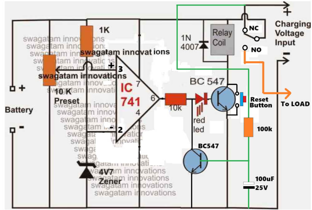
The push button allows you to revert the relay to N/O point and inverter mode whenever you feel, by breaking the latch.
No need to change the 4.7V diode, the auto cut-off can be set using the preset. However if you use a 11.6 V zener in place of the 4.7V, then you can eliminate the 10k preset, and simply connect the pin#2 directly to the battery positive, and connect a 10k between pin2 and ground.
But please note that there’s no overcharge cut-off in this circuit, it has only deep discharge cut-off…. if you want I can design both in one circuit, using a single LM393 Ic…
Hi Swagatam, Thank you for your advice, but I don’t need the overcharge option as I am making use of a Smart battery charger, which will prevent overcharging. I am first going to build this project on my breadboard, just to confirm that it works OK.
Just as a matter of interest I find it strange that the inverter(Chinese) does have a non adjustable cut off voltage of 10.5V. But at this voltage the battery charge is at 10%, which will damage or shorten the life span of the battery.
Kind regards.
Jan
Thanks Jan, that Sounds great, please try it and let me how it goes, of course it will work 100%, if done correctly with prior understanding of all the stages and component operations…
Please let me know if you have any problems…
Hi Swagatam, I have decided to go with a 11V Zener, however in your post to me you dit not mention were PIN 3 should be connected to. I then connected a 1K resistor to PIN 3 & Positive and removed the 10k resistor between 2 & Gnd. This gave me some results, however not the correct results. If I adjust my Power supply to 13.8V & press the reset button PIN 6 will go high, but as I reduce the voltage PIN 6 will only go low at 5V5 instead of 11V.
Any suggestions please.
Regards
Jan
Hi Jan, please build the circuit in the following manner:

You can see I have removed the capacitor from the base of the lower BC547 transistor since it was not required.
Please let me know how it works…
Please note that the adjustable power supply must be connected from the battery side (without any battery attached), not from the charging supply side.
Also, please disconnect the green connection from the base of the lower BC547 while testing the opamp cut-off operation.
You will find that the opamp switches the relay ON/OFF exactly at around 11V, but make sure the green wire connection remains disconnected.
Once the 11V cut-off operation is confirmed, then you can connect the green link back to its original form…
Hi Swagatam,
I have made the your cct diagram, but no luck. I have checked the cct numerous times. Component values are correct. Continuity is OK just in case there might be a bad connection somewhere. I have replaced the IC and Zener with new ones.
What I find strange is if I supply a battery voltage of 13V PIN 2 on the IC will also be 13V. If I now lower the battery voltage to 11V PIN 2 will also be 11V. If I lower the battery voltage to 5.3V the LED will switch off. I would have thought that PIN 2 would have stayed at 11V if the battery voltage was decreased from 13V to 11V, but it does not. I have also tried it with and without a load, but it makes no difference.
Any other suggestion’s?
Regards
Now I understand Jan why it is not working, I completely missed this point and I am very sorry about it.
Yes, the zener level cannot be stable here, so no fixed reference, so the comparator cannot work…
In that case, we have to either supply the zener resistor with a separate 12V DC, or go with the preset based circuit, as given below:
Please make sure to remove the green connection with the lower BC547 base while setting up the circuit.
Please let me know how it goes.
Sir
how can i attached my file with you?
Hi Nitesh,
Regarding which circuit do you want to attach the file?
Dear
i want to show my schamatic to you for POWER BANK To mobile bcz i choose 2 c pin & i am doubt on c pin which is connect with mobile bcz i add some Cap with that c pin ground & that ground came from Drain of mos
Nitesh, Please send it to my email ID
homemadecircuits
@gmail.com
I will check it…
This is exactly what I was looking for!!! Thank you very much!!!
Since I intended to handle a current no greater than 3 amps, a battery voltage of up to 20V, and protection of 14 or 15 volts, I was wondering if it would be possible to replace the TIP36 and TIP122 with ones with a lower current and thus achieve a smaller finished circuit. Thank you very much!!!!
You are welcome Matias, I am glad you found the above concept helpful.
Yes you can replace them with lower current BJTs, but TIP36 and TIP122 will ensure everything runs smoothly and coolly at 3 amp, and you may not need any heatsinks, so I would recommend keeping the design as it is…
I built the 3 transistor version titled “Deep Discharge Protection with more Accuracy” and it does work somewhat, but I have noticed that if the battery voltage drops low enough, say about 1.5 to 2 volts, the load will have power restored to it, thus fully depleting the remaining energy in the batteries, allowing a possible reverse charging event. Although this may never happen, I am using this circuit in a solar powered charging circuit to protect NiMD batteries that are charged from the solar panel. It is conceivable that low or no sun for several days could generate that kind of low voltage problem.
Thanks for testing the results.

You may try the following circuit, which will completely avoid the specified issue:
Thanks for the quick reply.
I will keep this circuit on hand in case I do have issues with the one I built.
I will be removing the batteries in the off season anyways, and I believe the very low voltage issue should not be a problem.
Yeah, sounds great…
Removing the batts during off seasons will solve the issue without any further modifications to the circuit…