In this post I will show how to construct a few fireworks ignition circuits which can safely ignite them via IR remote and timer. We have proposed three firecracker igniter circuit designs using ordinary components which we will be exploring them in detail.
Before we jump in to the circuit details, we have a word of caution; consumer Fireworks are dangerous and must be enjoyed under adult supervision and adults must have enough precautionary knowledge while igniting one and no fireworks must be ignited with close proximity to you or any flammable / inflammable substances or any living subjects.
The proposed project is here to make consumer firecrackers safer by igniting it from safe distance. The proposed circuits operate using rechargeable batteries and can ignite several firecrackers in one charge.
Now let’s dive into the first design which is simplest of the three.
Firecracker igniter using IR and monostable multivibrator:
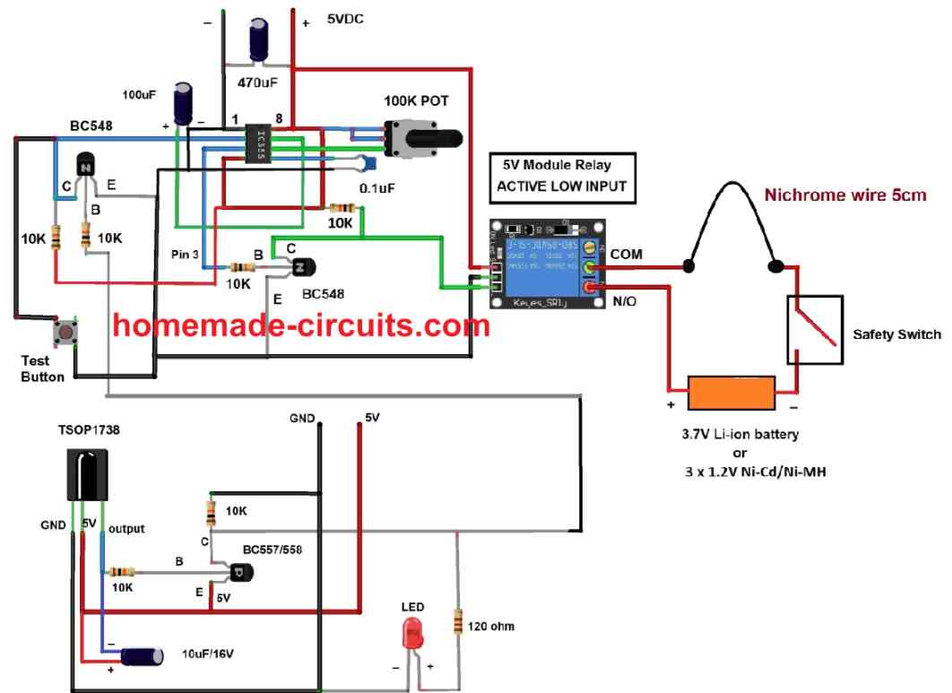
The above circuit consists of two stages: the first one is the IR stage which detects the incoming IR signal from any IR based remote controller. The second part of the circuit is a monostable multivibrator built using IC 555 which triggers the relay ON for a pre-determined period of time which heats-up the nichrome wire and ignites the fuse of the cracker.
Now let’s explore the two stages in detail and how the circuit functions.
Working explanation and detailed circuit description:
IR stage circuit:
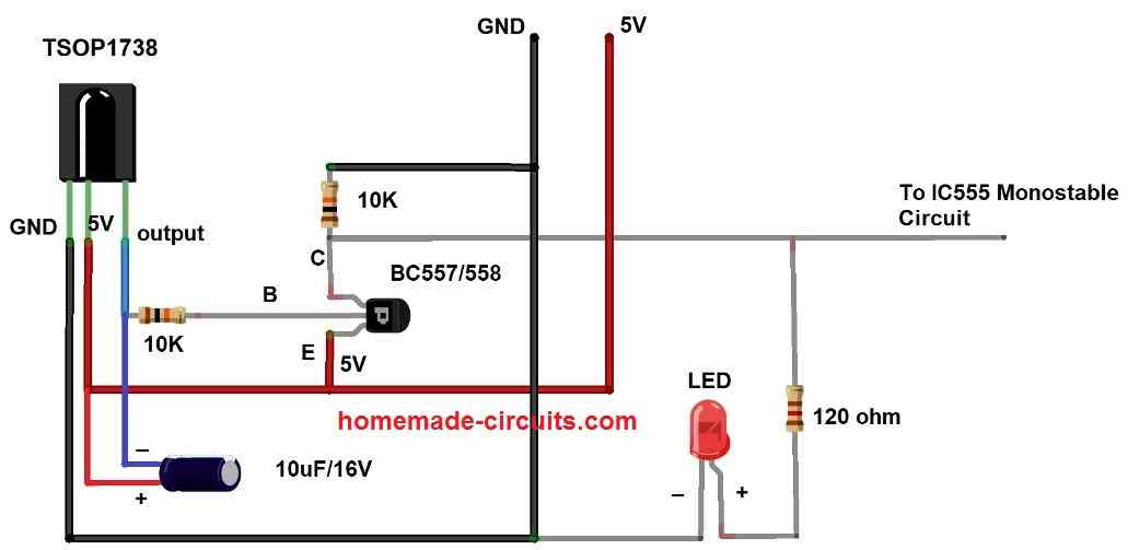
The above circuit is responsible for detecting infrared signal from any IR based remote controller. The circuit consists of an IR detector TSOP1738 which can detect infrared light with a carrier signal of 38 KHz, which includes most of the IR based remote controllers. Please note that 38 KHz has nothing to do with the infrared light’s frequency, but the (on/off) switching frequency of the (carrier) signal.
The TSOP1738 operates at 5V and consumes around 5mA. The output of TSOP1738 during idle state is HIGH and when it detects IR signal from a remote controller the output turns LOW.
IR based remote controllers does not output a steady Infrared light, but flashes, this is because each button on an IR remote has some special purpose and when you press a button the remote emits Infrared light with encoded signal in the form of flashing IR.
At the output terminal of the TSOP1738 we can detect the exact signal from a remote. However, these encoded signals (with data) are irrelevant for this project and we just need a steady signal to trigger the next stage.
To make the output signal constant we have connected an electrolytic capacitor with a value of 10uF which smooths the pulsating signal from the remote. The signal after smoothing capacitor is passed to buffer stage which utilizes a low power PNP transistor to strengthen the outgoing signal and also to invert the signal polarity so that the next stage of the circuit receives -Ve signal in idle and +Ve signal when a key is press on the remote.
A 10K pulldown resistor is utilized at collector terminal so that when the circuit is in idle state the output stays at LOW. A LED is connected to collector terminal with a current limiting resistor which glows when you press a key in a remote.
Monostable multivibrator:
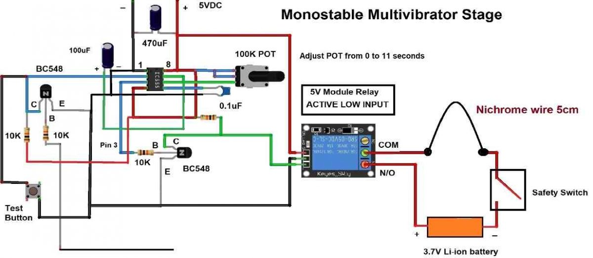
The above circuit is responsible for triggering the relay ON for a pre-determined period of time after a signal from IR stage is received. When the relay is activated the COM and normally open (N/O) terminals gets connected, this will complete the circuit and heats a piece of nichrome wire which ignites firecracker’s fuse. The circuit deactivates the relay after reaching the set time.
A 3.7V li-ion cell or Ni-Cd / Ni-Mh battery can be used for heating the nichrome wire. Please note that when the relay is triggered you can see the nichrome wire glowing red hot.
The monostable multivibrator circuit is build using IC 555. The IC’s output turns HIGH for a pre-determined period of time when a LOW trigger signal is applied at pin number 2. During idle state the pin 2 must be connected to HIGH, to accomplish this a 10K pullup resistor is used at pin 2.
The input HIGH trigger signal is received by a NPN transistor (from IR stage) which invert’s the output as -Ve signal and applies it to pin number 2.
The relay module we are utilizing is a 5V one with a breakout board and the relay activates when you apply a -Ve signal (Active LOW trigger).
At the output terminal (pin number 3) of IC 555 a NPN transistor is used to invert the +Ve signal to -Ve so that the relay can be triggered ON.
A test switch is provided to test / set the timing of the circuit and you can set time from 0 to 11 seconds to heat the nichrome wire by adjusting the provided 100K potentiometer. The recommended time is 5 seconds after which the relay deactivates.
Note: The fuse of the firecracker must be in contact the nichrome wire properly to start ignition. Make sure the provided safety switch is in open position when you are setting the firecracker’s fuse with nichrome wire, close the switch and move away to safe a distance immediately and use IR remote to ignite.
Firecracker ignition circuit design 2:

This design is an enhanced version of the pervious one, the difference between this and previous one is, the former ignites the cracker with single click and this will ignite only after three clicks and this will prevent accidental ignitions and false triggers. However, this doesn’t mean the previous circuit is a bad design. Now let’s dive into the details.
The first stage is IR receiver which is same as previous one and works in the same way.
The next stage is a debouncing circuit which will output a signal that is one second long to the next circuit stage. The debouncing circuit ignores accidental multiple trigger signal from IR circuit stage after a signal is received. A point worth noting is that the debouncing circuit is also a monostable multivibrator.
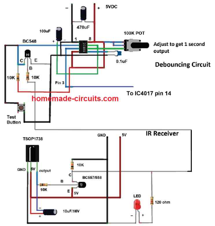
The next stage divides the output by three, this stage is what enabling us to press three clicks for ignition.
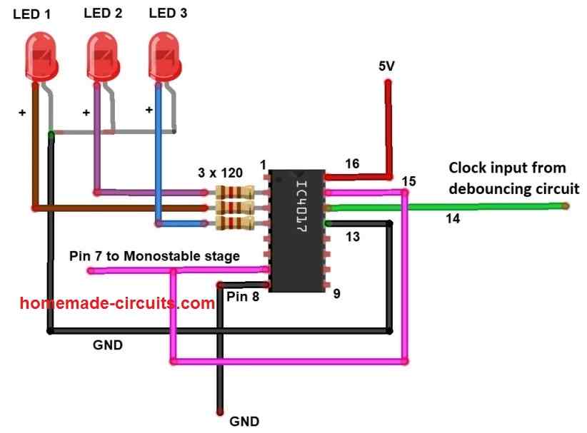
This stage consists of IC 4017 and three LED lights to indicate the how many clicks away from ignition. The IC 4017 is configured to divide the input signal by three, this is achieved by connecting the 4th output of the IC to reset pin 15.
Initially the LED 1 will glow, when you press a button on IR remote for the first time, the LED 2 will light-up (LED 1 will turn off) and when you press the button again, the LED 3 will light up (LED 2 will turn off) and when you press the remote for the 3rd time the circuit will give a signal to the next stage for ignition.
After pressing three clicks on the remote, the output pin number 7 (4th output) turns high momentarily which is fed to the next stage which is a monostable multivibrator circuit.
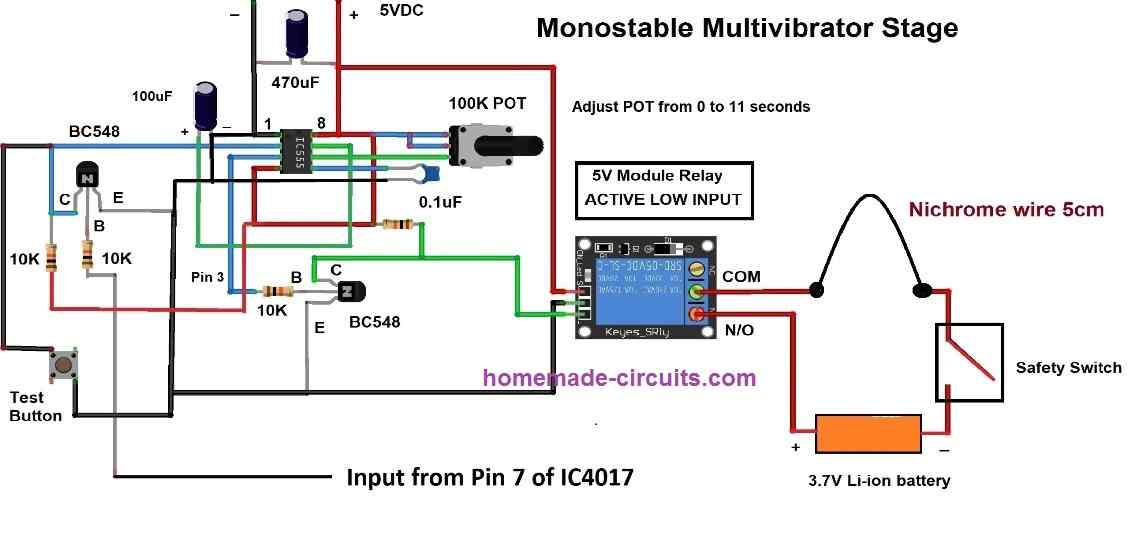
The output of IC 4017 is fed to the above stage and triggers the relay ON for a set period of time that you have set using the provided potentiometer (0 to 11 seconds).
Firecracker ignition circuit design 3:

The previous two designs are trigger using IR remote, in this design we have incorporated timer to trigger the ignition. Here you can select from 10 to 90 seconds to ignite a firecracker.
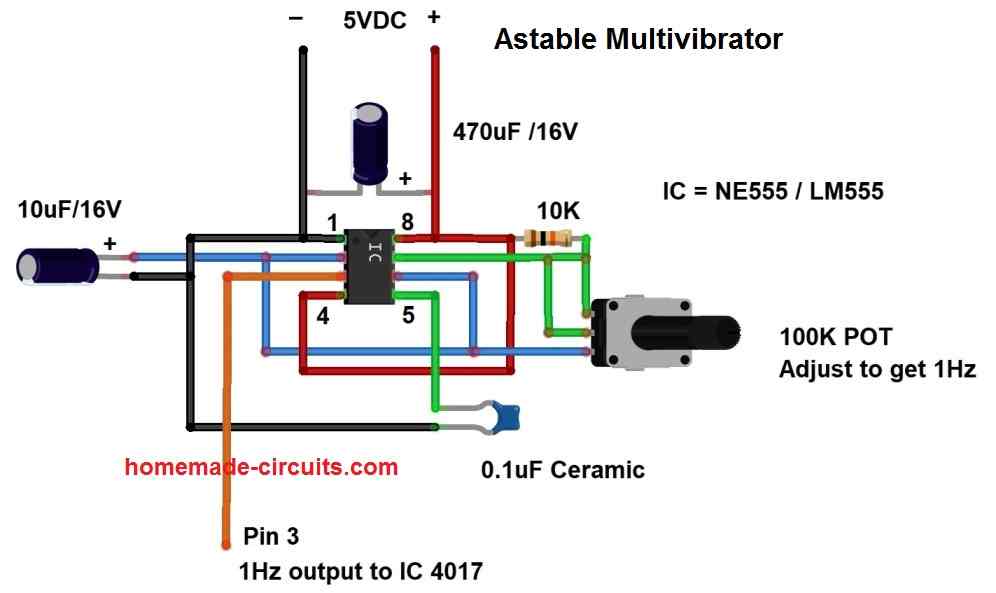
The first stage is an astable multivibrator circuit using IC 555 which generates clock signal at the rate of 1 Hz. Adjust the 100K potentiometer to get 1Hz at pin number 3.
The next stage is clock divider circuit which divides the 1Hz clock to 10 to 90 seconds.
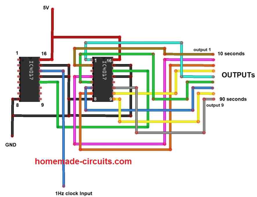
NOTE: There are nine outputs and you can choose an output between 10 and 90 seconds and connect the desired output pin next stage of the circuit.
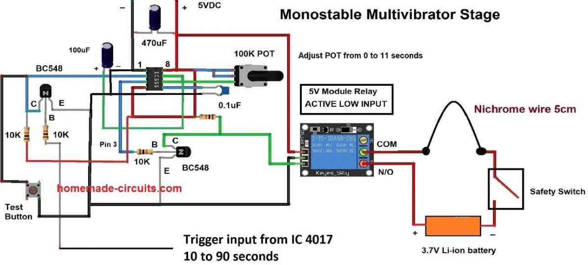
The above stage is a monostable multivibrator circuit which triggers the relay ON for pre-determined period of time, which can be adjusted using the 100K potentiometer.
Power supply:
All the circuit presented in this project are operated using batteries and no AC supply is used.
There are two separate power supplies in all the three proposed circuits, the first one is to heat-up the nichrome wire using 3.7V li-ion cell or three Ni-Cd cells connected in series. The second power supply is for powering the main circuit using 5V.
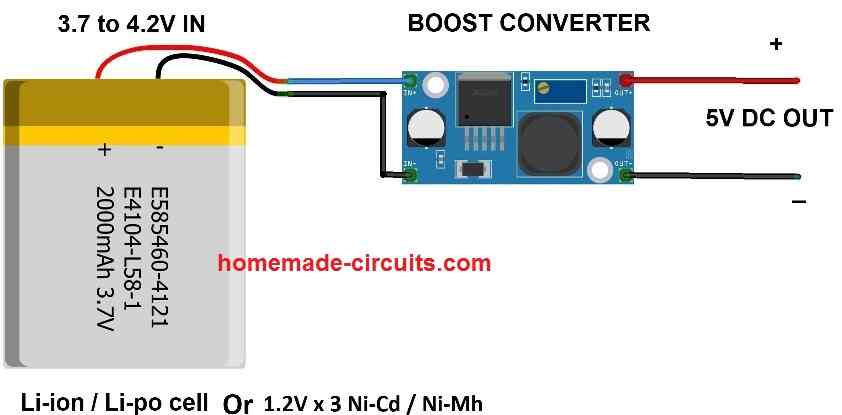
You can use any type of battery and switching buck/boost converters or voltage regulators to get 5Vas output, the above circuit is just an example.
Safety warnings:
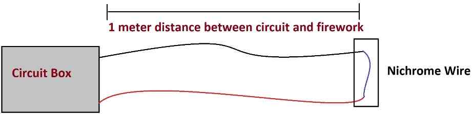
1) Make sure your circuit and batteries are in a safe distance and protected from sparks and flames using a hard plastic box and make sure that the cracker is at least 1 meter away from the circuit as illustrated above.
2) Make sure to open the safety switch mentioned in the circuit before setting up the cracker’s fuse with the nichrome wire. After closing the safety switch, please move away. This is to prevent any accidental ignition while setting the cracker’s fuse with the nichrome wire.
3) Make sure the relay is in deactivated state before you setup the cracker with nichrome wire. You can know whether the relay is ON or OFF by looking at the status LED that comes built-in with the module.




Need Help? Please Leave a Comment! We value your input—Kindly keep it relevant to the above topic!