This ultrasonic motion detector circuit project picks up movement of any object including human beings from a distance of 4 to 7 meters away. As soon as the motion is detected, the output of the circuit illuminates a red LED indicating the presence of an obstacle or an intruder.
However, using supplemental circuit stages connected to the output of the detector circuit, the device can be designed to switch on lamps, alarms, trigger a recording device, or maybe contact law enforcement. Furthermore, the circuit could be designed to play a message whenever a person or an intruder is detected moving across its range of detection.
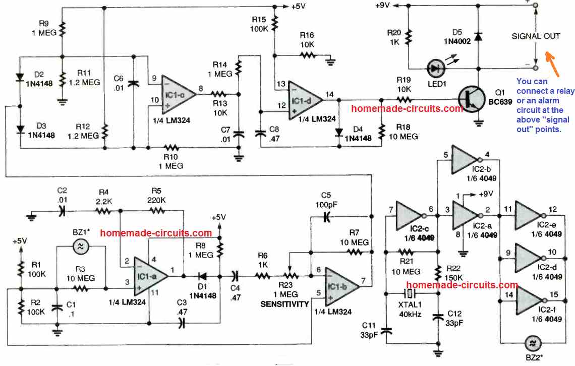
The circuit diagram for the Ultrasonic Motion Detector can be witnessed in the following figure.
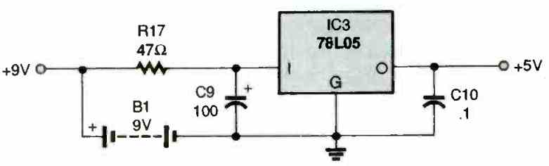
A 9 V PP3 battery, B1, instantly supplies electrical power for a few stages of the circuit. The battery can be also seen attached with a 78L05 regulator, IC3, that supplies a 5 V DC supply to various other stages of the circuit.
The Transmitter
The transmitter stage is essentially a crystal controlled relaxation oscillator developed using a 4049 CMOS HEX inverter, IC2. One of the IC 4049 portions, IC2c, together with resistors R21 and R22, and capacitors C11 and C12, "strikes" the 40 kHz crystal to force it into a continuous oscillating state.
The rest of the IC 4049 sections behave like linear buffers to operate a 40 kHz, ultrasonic transducer device, BZ2.
The Receiver
The receiver stage consists of 4 AC coupled sections, each one constructed using one of the four op amps from the IC LM324. In the 1st stage, the input voltage created around R1 and R2 is modulated through a 40 kHz, ultrasonic receiver transducer, BZ1, and the modulated signal is subsequently sent to the IC1a, where the frequency is amplified.
The receiver transducer picks up any kind of reflected frequency generated by the transmitter transducer, BZ2.
In case there isn't any motion, the resulting envelope signal waveform is simply produced in the form of a straight line.
Diode D1 and resistor R8 work like a negative peak detector to extract the envelope signal.
The second stage is configured around the IC1b, which amplifies the extracted signal again. The IC1b time constant is pretty sluggish which ensures that the envelope signal can be easily tracked.
The output generated from the second stage is a voltage level which determines the strength of the envelope. In the presence of a movement in front of the transducers, the envelope reflects the signal through a positive or negative beams.
Differential Amplifier (Window Detector)
At the third stage input we can find a differential amplifier configured around the IC1c and using a couple of diodes, D2 and D3. This stage picks up each of those positive and negative pulses.
In the absence of a motion in front of the ultrasonic sensors, the pin 7 potential of IC1b is 50 percent of the supply voltage which prevents both the diodes D2 or D3 from conducting.
The pin 8 potential of IC1c is as a result remains low. In case the signal strength increases over +0.7 volt (breakdown voltage of a silicon diode), causes the diode D3 become forward biased and conduct, enabling pin 8 of ICc to go high.
If the reflected motion signal drops under -0.7 volt, D2 gets forward biased and begins conducting, which in turn results in the output going high. Thus, the configuration works like a window detector. It detects voltage levels of the reflected signals moving either below or over a specified range.
The Monostable Flip-Flop
The 4rth stage of this ultrasonic motion detector circuit is structured around IC1d. This stage is configured like a monostable flip-flop. This section of the circuit converts any signal which enters via the filter into a pulse, which is big enough to trigger ON transistor Q1.
As soon as the BJT Q1 activates, LED1 illuminates, and it also generates an output voltage which can be used to operate an attached relay stage or some other alarm device hooked up with the collector of Q1.
The time delay provided by this IC1d monostable flip-flop is approximately half a second which is determined by the capacitor C8 and the resistor R18. The role of the diode D4 is to separate the charge/discharge time constants. This allows the circuit to activate instantly as soon as a movement is detected in front of the ultrasonic transducers, and additionally ensures around a 1/2 second delay for the resetting action.
About 40 kHz Ultrasonic Transducers
In the first diagram for the ultrasonic motion detector, we can see two transducers with the symbols BZ1 and BZ2. Both are 40 kHz type ultrasonic transducers.
BZ1 is the receiver transducer, while the BZ2 is the transmitter transducer.
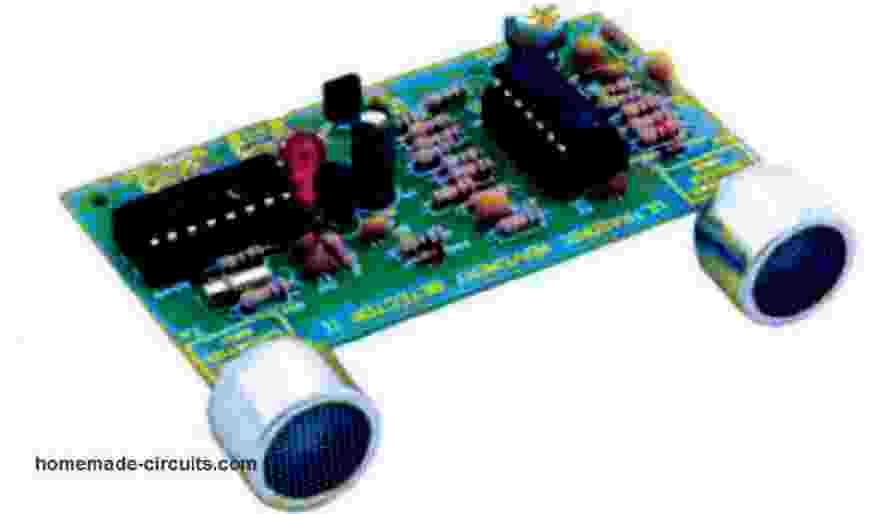
You must make sure that the two transducers are correctly matched, and therefore buy them only as a paired units. A matched transmitter/receiver 40 kHz transducer pair will have the respective initials printed on the back of their bodies, as shown in the following image.
The transmitter device will have the suffix T printed at the backside, while the receiver unit will have the suffix R printed on the pinout side of the body.
How to Set Up
Switch on ultrasonic motion detector circuit prferably through a fixed DC regulated power supply adapter. Install the circuit inside a noiseless room with nothing moving around in front of the sensors BZ1/BZ2.
Even warm air shuffling or, wind blowing, or amazingly, somebody chatting loudly could activate the motion detector, if the sensitivity adjustment is fixed to its maximum limit. After powering the circuit, allow the device to settle down for a minimum of 20 seconds to ensure the whole circuit will "calm down" electrically.
Adjust the 1M trimmer potentiometer to approximately 4 k ohms through your vision (put simply, assume the potentiometer is made up of settings starting from zero through ten, so now imagine setting it at the mark four).
At the downward adjustment of around 3 k ohms, the circuit will be most probably rendered too sensitive and might self-trigger. You may have to go through some experimentation to achieve the most appropriate setting for your specific motion detection requirements.
Once the ultrasonic motion is correctly set as described above, it is ready to detect motion in front of the transducers BZ1/BZ2 within a distance of 5 to 7 meters. You can test it by moving around the transducers within 7 meters and you will be surprised to see how well the unit detects the motion and triggers on the connected load which can be an alarm a relay or any desired load.
Using Ultrasonic Motion Detector as a Burglar Alarm
The best application of the above explained ultrasonic motion detector is probably in the form of a burglar alarm.
You just need to install the circuit in some corner of the area where an intrusion by a burglar is suspected.
Any burglar intruding or crossing the restricted area monitored by the ultrasonic motion detector will be instantly caught and the connected alarm will be sounded.
Simple Ultrasonic Proximity Detector using IC 555
The initial idea was to create the simplest possible ultrasonic detector. Therefore, systems with microprocessors or sequential logic were eliminated. The idea of emitting continuously and measuring the amplitude of the received signal was also discarded. As a result, it became impossible to measure distances, only detection in an all-or-nothing manner.
This means that if an object is at a distance below an adjustable threshold, it is detected. But once detected, it remains locked even if the object moves back slightly. There is a small hysteresis generated by the main idea of the circuit.
The chosen idea is to use the principle of the Larsen effect, well known in the musical field. The Larsen effect, or acoustic feedback, occurs when the sound emitted by the speaker returns to the microphone.
When a reflecting object is close enough to the ultrasonic receiver, it receives a weak ultrasonic signal generated by the transmitter.
This signal is immediately amplified and sent to the loudspeaker. The signal is sustained by the feedback and then shaped to be exploitable as an input compatible with logic circuits or other microprocessors.
This acoustic feedback is optimal at the frequency of ultrasonic waves, due to the presence of two elements: the transmitter and the receiver optimized for these frequencies.
This simplistic principle has some obvious drawbacks, the most important being the nature of the object to be detected, and another more insidious one is its sensitivity to excessively loud sounds.
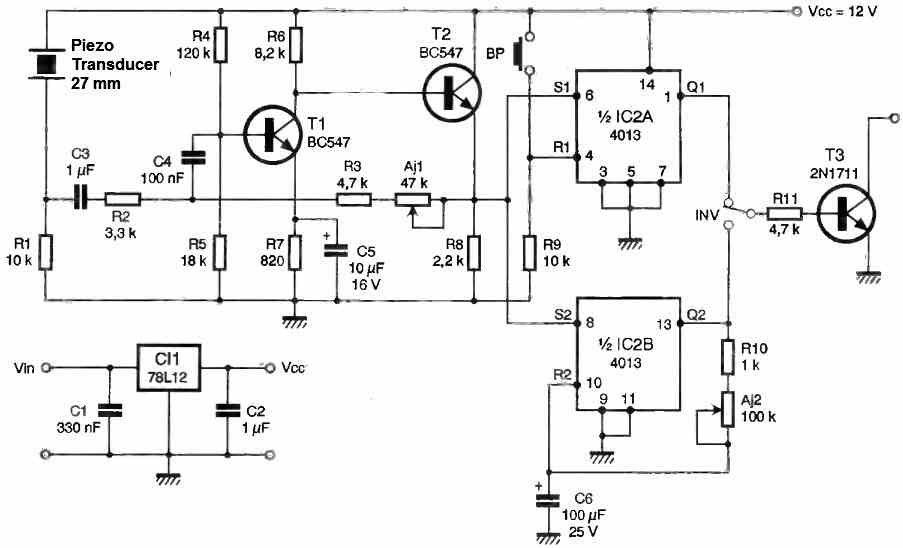
How the Circuit Works
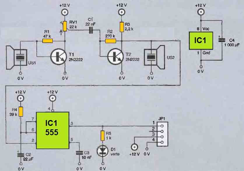
The diagram shows two parts: one is the amplification of ultrasonic signals, and the other is the signal shaping to obtain compatibility with other systems.
The ultrasonic receiver (US1) is amplified by a first bipolar transistor stage with adjustable gain via RV. This adjustable resistor allows the capture distance of obstacles to be adjusted.
The link between the two stages is made by a capacitive coupling. The alternating component of the signal is transmitted to the second stage by the capacitor C1.
This point is essential because the second stage is designed so that the voltage on the collector of T2 is just above the trigger threshold of the 555 monostable.
When the Larsen effect occurs, the voltage on the collector of T2 drops below 1/3 of Vcc and triggers the monostable circuit built around the classic 555.
The output of this circuit, which is in the low state at rest, switches to the high state for about 1 second. This duration is obtained by the choice of the two components R4 and C2.
The duration is equal to the product: 1.1 x R4 x C2.
To verify the proper functioning of the detector, a green LED has been added to the circuit. Let's not forget the big capacitor C4, essential in the presence of inductive loads such as the motors of a robot.


Questions & Answers
OLA. NÃO VEM AO CASO MAS ESTÁ PERTO. PREGUNTA: ONDE POSSO COMPRAR CAPSULAS DETECTORAS QUE POSSAM VIR PARA BAIXO DE 1 HZ OU LÁ PERTO. NA CHINA ELES DIZEM QUE SIM, MAS É MENTIRA. MUITO OBRIGADO
Hello,we try to build this circuit by ourself but when we finish the circuit it didn’t work ,we has already checked all the list you give and tested all the possible problem but it still can not work ,we found the lm324 pin 7 potential can’t be stable ,even we adjusted the 1M trimmer potentiometer the the most sensitive it still can’t work, please give as some suggest thanks you!!!
Hello, as you can see there are so many parts and stages in the circuit so it is difficult to judge which connection or part in your circuit my be faulty or malfunctioning. You will have to read the article and try to troubleshoot the circuit yourself.
Thanks for your reply. We had checked the point which you remind and every points are ok but still can’t work.
The last question hope you can help us ! Does this circuit have any check points?( ex: lm324 pin 14 need how much voltage for this circuit ),because in our testing ,the result is LED wasn’t work but when we checked the lm324 pin 7 and 8 the results are fit the article says.
Thanks for your helping it’s very helpful for us
Did you check whether BZ1 is generating 40 kHz frequency or not, with a frequency meter?
BZ1 is supposed to generate 40 kHz frequency and BZ2 is supposed to receive this frequency and activate the op amps.
Did you buy BZ1 and BZ2 as pairs?
You can touch pin#3 of IC1a and check whether the LED lights up or not.
How did you build this circuit, did you build it over a breadboard? If yes then it is never going to work….you must build this project by soldering the components over a strip board or a PCB.
If you are having difficulty building this project you can try other easier ones as given below:
https://www.homemade-circuits.com/ultrasonic-burglar-alarm-circuit/
https://www.homemade-circuits.com/best-ultrasonic-transmitter-receiver-circuits-for-all-hobbyists/
The circuit does not have check points but it is built using different op amp stages, so each stage must be checked separately as per the function of the specific stage, as explained in the article.
Thanks for your reply . We have another hope sir .Do you have the testing video ? could you sent it to my email please!
(liam5011616@gmail.com)Apologize for disturbed you so much
Hi Liam, Unfortunately I do not have any videos for this project. Actually the above circuit was not designed by me, it was contributed by another author. It seems the author has taken this circuit from some old electronic magazine, because from the print of the schematic we can make out that it is not hand drawn rather taken from a magazine.
Did you measure the frequency across BZ2? Are you getting 40 kHz there?
Please remember that the transducers BZ1 and BZ2 have different specifications, one is meant for transmitter and the other one for the receiver.
hello i purchased a few hc-sr04 being a newbie and trying to learn i thought i could supply power to the circuit along with an led and it would light the led in the presence of movement. can you design a circuit to help me finish this pre-built sensor please?
Hi, as far as I know, the hc-sr04 can be used only with an Arduino or a microcontroller circuit. It cannot be used with a discretely built circuit or an analogue circuit.
Ver good project. It will be nice, if you provide the source of the components Sir, like 40KHz ultrasonic detectors. I made few of your projects and they are all working fine. LPG Gas detector, intruder alarm with proximity sensor.
Thank you Satyadeo, you can get the parts from any online spare part dealer, you can even get it through amazon, ebay etc. You just have to search for “electronic components online”
grate information Sir
Thank you Sir!
Hola Swagatam! ¿El oscilador funciona conectando el positivo(+) solamente al pin 1 del IC 4049? Saludos de Buenos Aires, Argentina.
Hello Beto, that’s right, the 4049 section requires the supply only across pin 1(+) and pin 8(-)
Once again, a very detailed design. You are my favorite teacher. Precise and detailed. One question for you Sir. Do you do anything with Arduino type circuits? I am trying to learn about that particular tupe of thing. Hardware and programming. I think you could definitely be the man to teach that subject as well. Keep up the great work. And thank you.
Thank you Mark, Glad you liked the post. My Arduino knowledge is just as good as yours, so it is me actually who is trying to learn coding at the moment. However, I have an artcile that can be a good starting point for all newcomers who are try to master Arduino. Here’s the link where you can find the basic programming examples:
Learning Basic Arduino Programming – Tutorial for the Newcomers
Dear Swagatam! I really do appreciate you and for sure a lot of people! You are the epitome or the TRUE meaning of the word HELP. You are awesome! You wil surely have and are having a good life! More power to your Spirit! 🙂
Thank you so much Kitt, for your kind words. I am always happy to help!