The following LED emergency light with battery over charge protection feature circuit was designed by me in response to the request sent by PP.
Main Features
In this article I have explained an LED emergency light circuit with advanced features such as,
- over charge battery cut off,
- day time auto-disable,
- and need less to say that the circuit switches ON the LEDs automatically when AC mains fails and reverts to charging mode when power is restored.
- The good thing about this circuit is that it incorporates ordinary, cheap components which can be easily procured from the local market.
Using Transistors only
The following design of the proposed day/night automatic emergency LED lamp circuit with battery overcharging protection uses only BJTs and looks indeed very simple. Let's understand how it works:

How it Works
Mains AC To DC Power Supply
We first see that the circuit starts with a small 0-12V transformer. We take the 220V AC and we let the transformer drop it to around 12V AC, then we send this AC through four 1N4007 diodes which make a full bridge rectifier.
So the AC becomes DC here, then the 1000uF capacitor smooths the DC and removes the ripples. So now we get around 14V to 16V DC during no load.
This DC is used for battery charging and also used as the signal which tells the circuit that mains is present.
LDR Light Sensor Section
We also see an LDR with a 10k resistor and a BC547 transistor, so this part senses darkness.
When the LDR receives light then the LDR resistance becomes low and that pulls the BC547 base high so the BC547 switches ON.
Conversely when it is night then the LDR resistance becomes high and that allows the BC547 base potential to fall, so BC547 turns OFF.
This OFF allows a positive biasing signal towards the TIP122 base and turns it ON, so that the LED panel can switch ON, but only when the mains is also absent.
Mains-Fail Detector Section
Now the BC547 transistor with one small LED near the base, this part also tells the circuit that mains is present or not.
So when mains is present then this BC547 becomes ON and it grounds the base of the TIP122, so that means TIP122 cannot turn ON.
So even in full darkness the LED panel will remain OFF as long as mains is present.
When the mains fails then this BC547 becomes OFF and it frees the base of TIP122, so now TIP122 will respond only to the LDR signal, as explained above...
TIP122 LED Driver
We see the TIP122 connected to all the LED strings through 1k at its base, so this is the main battery power switch.
When the LDR section says it is dark and when the mains section says mains is absent then the TIP122 receives base current.
So TIP122 turns ON and it allows the battery voltage to reach the LED panel, and the LEDs glow from the battery. But as soon as light returns or mains returns then the TIP122 switches OFF.
LED Panel
We see many 5mm white LED groups each with 680 ohm resistor. All of them are connected in parallel and all of them get the supply from TIP122. So the brightness is good and stable.
Battery Charging Section
We see the battery being charged through the TIP127 PNP transistor, so the DC from the transformer enters the TIP127 and then reaches the battery.
As long as the battery voltage is low the charging current flows. The BC547 with the preset in the lower right corner senses the battery voltage and controls the corresponding BC5547/TIP127 switch.
Battery Overcharge Cutoff
We see a 10k preset, a BC547 and some 10k resistors, so the preset is adjusted to pick a small sample of the battery voltage.
When the battery voltage reaches the full charge level then the bottom left side BC547 turns ON. When this BC547 turns ON then it pulls the adjoining BC547 base low, turning it OFF, which in turn switches OFF the TIP127 also.
This disconnects the supply to the battery and the battery stops charging.
The small LED near this bottom section shows the charging condition. When charging is happening the LED remains ON, and when the battery becomes full the LED switches off, but this ON/OFF illumination process is gradual and slow.
Complete Summary
Now we can summarize the behavior in simple crude steps.
Day + Mains
When it is day then LDR keeps top BC547 ON, grounding the TIP122 base. Similarly, when mains is present then this same BC547 is ON, grounding the TIP122 base. So in these both conditions TIP122 stays OFF. LEDs are OFF. Battery charges until full.
Daytime light + No Mains
When it is day then LDR keeps the BC547 ON. When mains fails then mains BC547 also becomes OFF. But still TIP122 gets no drive, because of the LDR and day light...So LEDs remain OFF.
Night + Mains
When it is dark then LDR turns the top BC547 OFF. But since mains is present then the mains BC547 has to be ON, so TIP122 base is again grounded. LEDs remain OFF.
Night + No Mains (This is the only time LEDs turn ON)
When it is dark then LDR resistance is high and the top BC547 turns OFF. When mains fails then mains BC547 is OFF. In these two conditions TIP122 gets proper base current. So LED panel turns ON from the battery.
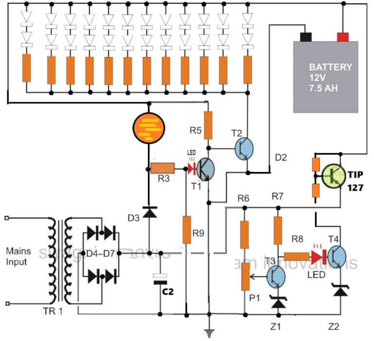
Using IC 555
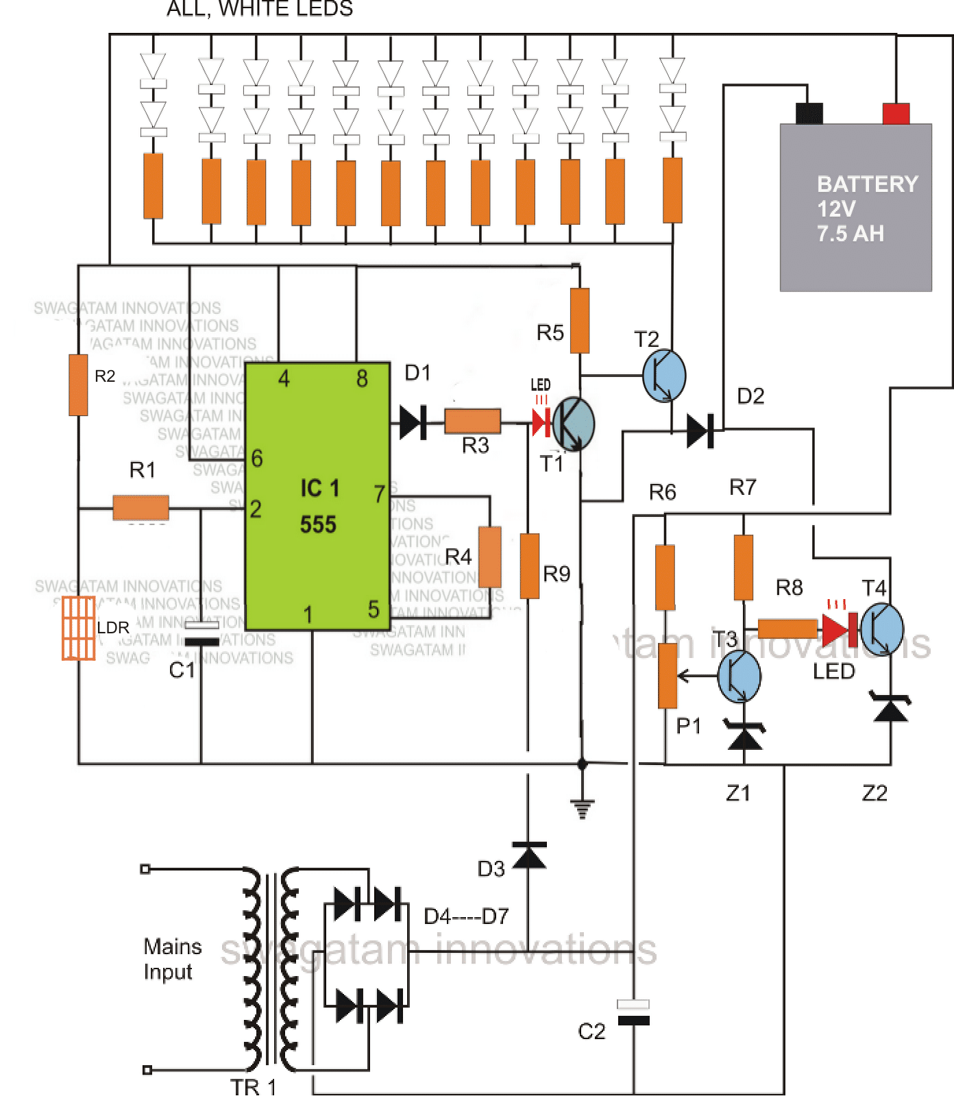
The above circuit can be also built using a 555 IC comparator circuit for sensing the day/night conditions and LED turn ON/OFF switching.
Circuit Operation
Let's try to understand the circuit functioning with the help of the following points:
IC1 which is our very own IC555 has been set as a comparator. During day time, the light over LDR keeps the LDR resistance low such that the potential at pin #2 of the IC is kept well over 1/3Vcc. This situation ensures that the output of the IC at pin #3 stays at logic high.
The logic high at pin#3 of the IC keeps T1 switched ON, which consequently keeps T2 switched OFF.
With T2 switched OFF, the LED array remains inhibited from the ground connection and therefore the whole white LED array also stays shut off.
Another factor that keeps T1 switched ON and T2 switched OFF, is the voltage from the transformer power supply stage.
This function is implemented via the resistor R9. This also means that as long as mains AC is available, T2 is restricted from conducting and therefore the LEDs cannot light up.
Now suppose the mains power to the transformer fails, and assume that this happens during night or complete darkness, pin#3 of IC555 reverts to zero and also there's no voltage from the power supply, means T1 has absolutely no base bias and therefore has to switch OFF.
This instantly prompts T2 to switch ON and consequently the entire LED array also switches ON, providing the required emergency illumination to the surrounding.
MAKE SURE THAT THE LIGHT FROM THE LED DOES NOT FALL OVER THE LDR, WHICH MIGHT TRIGGER A RAPID UNDESIRABLE SWITCHING OF THE LEDS.
The battery charging section consists of T3, T4 and the associated parts. P1 is set such that it switches ON T3 when the battery voltage reaches just above 14 volts.
The moment this happens, T4 switches OFF, cutting of the negative supply to the battery and restricting any further charging of the battery.
Diode D2 ensures that the battery receives the negative supply during the charging process only through T4 and also provides a normal negative path to to T2 and the LED array when they conduct.
The left side LED indicates, mains power ON or presence of day light.
The LED at the right side indicates, battery is charging.
Parts List
- R1 = 2M2
- R2 = 1M
- R3, R4, R5, R9, R6, R7, R8 = 4K7
- ALL LED RESISTORS = 330 OHMS
- D1, D2, D3 = 1N4007
- D4----D7 = 1N5402
- C1 = 1000uF/25V
- C2 = 1uF/25V
- T1, T3 = BC547
- T4, T2 = BD139
- Z1, Z2 = 3V/400mW
- P1 = 10K PRESET
- IC1 = IC 555
- TRANSFORMER = 12V, CURRENT = 1/10 OF BATTERY AH
- LEDS = WHITE 5mm, OR AS PER CHOICE.
- BATTERY = 12V, AH = AS PER LED POWER AND BACK-UP REQUIREMENTS.
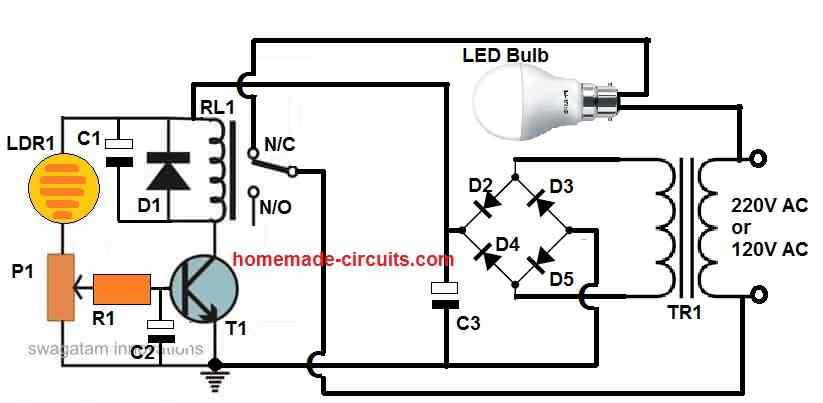
Using a Single PNP BJT
The above circuit can be much simplified by eliminating the IC555, and by using just a single PNP transistor instead of two NPN in the battery auto-battery cut of section.
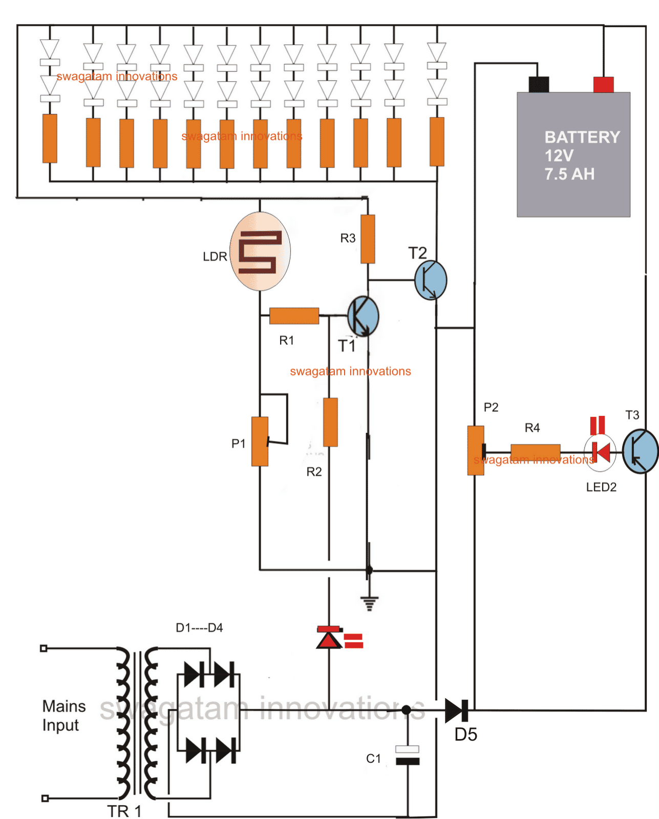
P1 is used for adjusting the ambient light threshold at which the LEDs stop illuminating.
P2 is set such that at 14.6V (across the battery terminals) the base LED becomes very dim, hardly visible, and at 12.5V it's brightly lit.
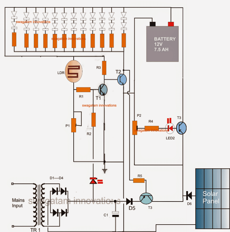
Adding a Solar Panel
The above circuit can be also coupled with a solar panel for getting an automatic charging facility from both the sources that is from the panel during day time and from mains after the sun sets.
Parts List
R1,R2,R3, R4, R5 = 1K
P1 = 470K
P2 = 1K
C1 = 1000uF/25V
D1---D5 = 1N4007
T1 = BC547
T2 = 8050
T3 = TIP127
ALL LED RESISTORS = 330 OHMS
LEDS = WHITE, 5MM
LDR = ANY STANDARD TYPE
TRANSFORMER = 0-12/1AMP


Questions & Answers
In the circuit using a single PNP transistor, the LDR responds correctly, but when the transformer is plugged in, the LED strip still lights up. It turns on whether the transformer is plugged in or not.
Please try this simplified design and let me know:
Good day sir! I’m currently taking an engineering course, and I am using this circuit for my project. I tried building this schematic on Proteus but it seemed like it doesn’t work. Can I ask what can be the problem? I also tried it using Voltsim on mobile but it doesn’t work too. The voltsim shows that even if you cut off the AC source, the output of the IC doesn’t change, and T2 also doesn’t turn ON, therefore making the LED arrays still unconnected to ground.
Hi Marvin, I understand you are having problems simulating this circuit on softwares…
However, I would suggest you that if you want to become a real engineer then you must make an effort to understand each section of the schematic and then simulate in your mind, whether it will work correctly or not.
If you depend on simulators then that won’t help because simulators are never perfect.
As you can see, the IC 555 is powered by the battery also, and not with the AC adapter alone, so the IC output is dependent on the battery power and the ambient light on the LDR. For T2 to turn ON, the AC/DC adapter must be off, and also the LDR must be in perfect darkness.
So I would suggest you to build this circuit stepwise, and confirm the results, and then finally join all the stages to complete the project.
If you want an even easier design, I can give it to you.
Good day sir, I’m an engineering student and I’m trying to make this circuit into a project. Regarding to the circuit diagram that uses 555 timer as a comparator, does R1 to R9 need to be all cement resistors, or 1watt resistor, or 1/2watt resistor?
Thanks Andrew, for choosing this circuit for your project,
All the resistors can be 1/4 watt, 5% CFR resistors.
Let me know if you have any further questions…
Is it possible to use an LED strip?
Yes, it is possible, in that case do not use the external series resistor, since the strip itself may have a built-in limiting resistor…
What is the wiring if I want to add a switch to turn off the light when it’s not needed?
You can add an ON/OFF switch between the connection that goes from the battery positive and the LED anodes…
I tried the circuit on the breadboard. The two LEDs light up, but the LED strip doesn’t work.
You will have to test each stage separately and confirm their working separately…the 555 stage first, then the two transistor stage and then gradually integrate them.
But I think it can be difficult for you since you appear to be a newcomer in this field.
I will design a better and simpler circuit for you which you can just hook up and get the results.
I will update it soon here..
hello sir
thanks for voluntarily sharing your innovative ideas and knowledge with us on this open platform.
I am a senior student reading electrical engineering and currently working on my senior project (Automatic Emergency light) with which I’m finding it so difficult to come up with a comprehensive Circuit Diagram. Please, I am appealing that you please help me do a circuit diagram for Automatic Emergency Light with Relay (and NOT LDR) because I want the LED bulbs should glow only during power outage and using the relay as automatic switch.
Hello Prince, a relay is actually not required, you can control the LED using a transistorized circuit itself. You can refer to this post for more info:
https://www.homemade-circuits.com/how-to-make-efficient-led-emergency/
I have a 3.6V recheargeable battery powering an SMD array, is it possible to use a lower V transformer (5 v) and keep same circuit?
yes that’s OK, just remove Z1, and Z2 and replace with direct links.
is it possible to cuf off load (led panel) when battery get discharged at 10.5v
if you add 3 LEDs in series instead of two, then this can be implemented automatically
please tell me
sir which software your using for designing the circuit???
Supeeeeer!!!!!
Hi
How to adjust the over charge cut off circuit for a 4v 1ah battery?plz help..
Hello Swagatam,
I built the 2nd circuit you gave and checked a couple of times to make sure everything is connected to each other well. I got some issues though. First of all, I would like to use a led strip (rated 12V – 4,8W per meter), but I don't know how much length I need yet. I also discarded the LDR section with the LDR, P1 and R1. A couple of times I tried, it worked as expected. Later on, it didn't work. Here are the issues:
1- While it was working fine, when A/C mains was cut off, it took some 7-8 seconds for the leds to light up 🙂
2- As you mentioned in the description and in some of the answers you gave, I adjusted P2 to get 14V from battery terminals and I got a dim red light, but when it went down to 12V the light got dimmer, almost not visible.
3- With the use of strip leds, I guess I fried T2 (S8550), because after a few tries turning A/C power on and off, the leds starting lighting up with the A/C power on turning off when the power goes off 🙂 Also, the transistor was pretty hot.
yes obviously T2 must be dimensioned as per the LED current otherwise it will keep blowing of.
Only T2 and R3 will need to be upgraded as per the load current rest will as is unless any other parameter such as battery is upgraded too.
R3 = Batt supply – LED operating voltage / LED operating current
Thanks for your reply, you've been pretty helpful..
The only direct connection between T1/T2 and the capacitor is the negative pole, which I guess not very important.
As I presumed, I had fried T2 and when I replaced it, it worked fine again. Then it got fried again as I forgotten to remove some part of led strip before plugging it back :))
I realize that it is a crude design, still it is important for me to start building something small and make it useful at home..I have seen the other project you have mentioned and I will surely have some questions for that one too 🙂
If I change T2 to a more powerful transistor, would I be able to use it with a load of 2-2,5A? Or I need to upgrade the whole circuit for that? For T2, I found BDX53C, which seems to be pretty powerful, still not sure if I can use it for the same purpose, or do you have another suggestion?
Thanks in advance..have a great week
Hello Alihan,
the issues which you have mentioned can never take place because there's no possibility of those happening.
there's no capacitor associated with the T1/T2 so the delay effect cannot happen.
I hope you have only removed the LDR, R1 and P1 in your circuit and kept rest as shown in the diagram with R2 connection intact with the base of T1?
T2 can only become hot if the LEDs current is much higher than its tolerance level.
The charging LED will become dim as the battery voltage reaches 14V and vice versa so that's fine.
when mains is present T1 will be triggered ON through R2, which will keep T2 switched OFF, keeping the LED bank switched OFF, so the LEDs can never light up when mains is present unless one of the transistors has gone faulty.
by the way this a very basic and crude design so you cannot expect high precision from it.
for a high precision you can probably refer to the following design.
https://www.homemade-circuits.com/2015/10/smart-emergency-lamp-circuit-with.html
Hi Sir. We want to make a request. Is it possible to add a feature on this circuit? We would like to add a fan in this circuit so we can use it when there is power failure. Thank you.
Hi Mayu, you can connect the fan exactly where the LEDs/resistor network is connected that is across the positive of battery and the collector of T2
Sir
Please reply me
I have 12v 12AH led acid battery. I need to charge it. Please tell me the spec of 12v transformer
Varun, you can use a 0-12V 2amp transformer for it, connect a bridge-rectifier with a 6800uF/25V to getting the required 14V 1 amp charging output for the battery.
Sir
I have 12v 12AH led acid battery. For this how much Amp transformer need for making charging circuit
Thank you
Hi am Akhil
In the first circuit circuit using IC555,where should the earth sign indicated point be connected?
to the battery -ve or bridge circuit's -ve?
Hi, it's already connected with the negative of the bridge rectifier….no need to connect it anywhere else.
what changes should be made to the circuit if a large number of LEDs (say White coloured,75 or more in number) should be included??
battery, T2 and the transformer rating will need to be increased accordingly
Sir can i ask where is the positive and negative in solar panel . the positive side is connected in the diode right ?
yes that's correct
Hi Swagatam..
I just constructed the second circuit using 6 volt battery, with 24 Led, single series with R combined 3 diodes. For the emergency light, it is functioning well. However, for the charging and cut off section, i set up the LED with the fully charged battery (6.9volt) by triming the pre set of TIP 127, to get very dim LED. When the battery discharged to 4.4 volt, the LED is still dim, then i detached the Battery and measure the collector voltage of TIP 127, the output is zero. I trimed the VR in such away to get the output of the collector to 8.5 volt, the LED became very brigth. I put on the battery and let it get charge. After the whole day, i still saw the LED bright. Then i detached the battery and measured the voltage of battery, it was 6.9 volt. i put on the battery again and trimmed down the LED until dim. After that, i detached the battery and measure the output of TIP 127, it was zero volt. Could you please advise me, what is my fault. I use 7.5 volt transformer of 1 amp and 6 volt 4.5AH batery.
Many thanks
Regards
Kanta
Hi Kanta,
using a single transistor as a sensor can be very crude and produce less accurate results…still you can try attaching a 3V zener diode in series with the base of the transistor (cathode towards base) and check the results, or you can opt for the next design using two transistors.
DEAR SIR
i implemented your circiut with ic lm555 ,the current with leg 3 of ic is fllowing in every condition of LDR if we opened the leg 3 of ic the emergency light works fine plz help me to make LDR operational in this circiut
2.bp.blogspot.com/-eT2gHZxSr_A/UcEtp0coNDI/AAAAAAAAEhU/_9SJyCbGqWQ/s320/emergency+light+with+overcharge+cut+off.png
Dear Farhan,
in the absence of light on the LDR, pin3 will stop producing a voltage…..so make sure the LDR is held in sufficient darkness for this to happen…..or reduce the value of R2 until pin3 becomes zero volts at the desired darkness level
dear sir i implemented your fiirst circiut with ic lm 555 i am having an issue emergency leds are not glowing becasue in every case current is flowing from leg 3 of ic if we opened leg 3 of ic the emergency light works fine plz help me and make circiut operational with LDR
image url is
2.bp.blogspot.com/-eT2gHZxSr_A/UcEtp0coNDI/AAAAAAAAEhU/_9SJyCbGqWQ/s320/emergency+light+with+overcharge+cut+off.png
Hi sir
I am so glad to see ur interest towards electronic circuitry ..
So eagerly waiting for circuit which will be having following (few or all) features
-Low Battery Cut-off
– Overloading protection
– Short Circuit protection
– Reverse current protection
– Reverse polarity protection
– Thunder protection
– Over discharge protection
– Auto battery shut-off at Low voltage detection
– Overcharge protection
– Auto charge stop/ High Volt Detection
– Battery capacity level display(SOC)
Making this circuit for underprivileged location as donation for poor via charity
So hope I can have one ckt diagram with some or all features mentioned above or lts link..
Looking for ur reply ..
With full excitement
Thank you
Regards
Lokesh
If successful I am in plan to put ur & website name on my device 🙂
As part of tribute to you sir
Email: Lokeshelectronic@gmail.com
Plz WhatsApp me sir if possible to
9986829004
Thanks Lokesh,
I'll try to publish it soon…..please keep in touch.
Sri. Majumdar,
You say that the IC555 in your first emergency light ckt. can be dropped and have given the modified ckt. without the use of IC555. Does the second ckt.retain all functions of the first ckt?
svs
it seems in the 1st ckt, no need of z1,z2.. whats the function?
it delays the response…but it's not important.
hello sir swagatam.
sir i want to create your wonderful circuit above but the problem is., i never have bc547 if i substitute this by 2n5551 what is the difference and what transistor that can be substitute in bd139 if i never have tip122.,., i wait for your answer sir.,., thanks.,.,
hello eroll
although not very much suitable, 2N5551 can be used in place of BC547, for BD139 you can use any other equivalent rated to handle at least 2 amp at 30V