Low frequencies predominantly cover our earth's atmosphere. This range of frequency may be created by many different sources which may be quite unknown and strange. A VLF sensor equipment can be made to trace these frequencies for investigating the intriguing secrets hidden behind it. Mr. Steven Chiverton investigates.
VLF Receiver for Sensing Lightening and other Tiny LF signals
This is the vlf receiver circuit that I've upgraded and modified it senses ac fields lightening and even receives ship and aircraft radio too.
Now this is what the circuit looks like without the upgrades and modifications.
I've even used a gravity wave detector circuit added to it and also other experimental circuits
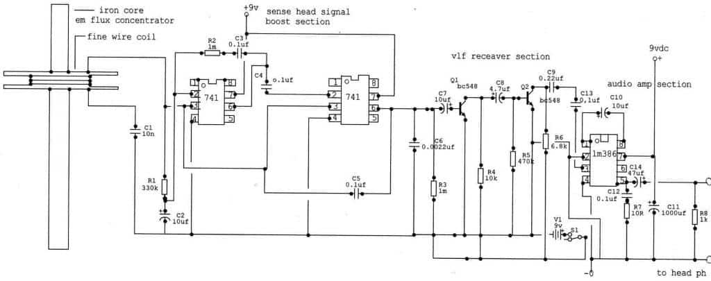
This is my modifications to the vlf receiver circuit to sense lightening and em pulses and signals
Not very good at the technical explanation well ill give it a go.
The sensing signal booster on the far left hand side I bread boarded that to test it to see if I can get more signal boost with it,
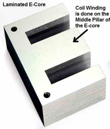
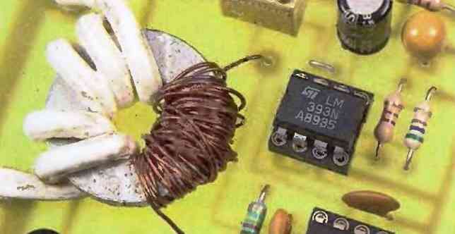
The coil with its inductive nature pending on the amount of winds of thin wire and also the flux concentrator, this concentrates the em flux when a signal is induced into the coil and it increases sensitivity more.
If you was to take it out the sensitivity and strength of signal would drop but then your in another mode as the circuit would still act as a lightening detector sensing lightening.
The crackles will indicate that and the ac environment well it would sense that but at a lower response to it unless you re insert the flux concentrator core then the hum from ac mains will be increased a lot .
Now the vlf receiver section that will allow the signals from the sense head section to pass through.
Very low frequency signals will pass through still but are filtered some more with the 0.1uf ceramics then it will still sense ac mains at a lower response with the flux concentrator core removed than it would with the core left through the coil.
So if your outside the electromagnetic environment leave the core in for maximum sensitivity. It would be a good idea not to wear any battery operated watch as mine gets sensed so easily with my other 2 vlf receiver circuits.
Your ears will get a pounding from the loud ticks as the EM pulses from your watch are greatly amplified through the whole circuit.
The em signals from your watch are very low frequency signals so these signals will pass through the vlf receiver circuit to unimpeded.
The last circuit is the audio amp section so you can plug head phones in to listen.
Also the vlf receiver circuit takes a 9 volts battery and its input voltage is linked to the front sense head section so they can both share one 9 volts battery.
The second nine volts battery powers the audio amp section and its good this way if you switch off the vlf receiver section the audio amp section appears to still be using some of the circuit.
When power is removed from the vlf receiver section and you will still get some signals coming through it somehow.
I've got these same results with the first 2 other upgraded modified vlf receiver circuits.
It can still sense em pulses from a ticking watch to but at a lower response to the flux concentrator is made up of a number of barrel shaped torroid slipped over a stick or a pole shaped core inserted through the coil.
The circuit also sounds like a comic receiver for weird signals to with the core taken out so it dose what I think a vlf receiver dose then .
The sense head setting has been constructed onto a bread board and tested with a already made vlf receiver with audio amp.
I forgot to mention the circuit also acts as a pick up as a radio or tape player when brought close to the sense coil the coil and circuit pickup the voices from the speakers of any tape player and may also do the same for a telephone.
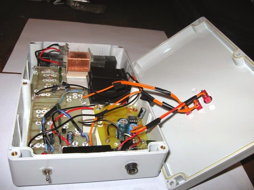
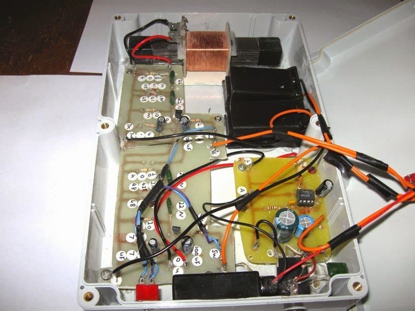
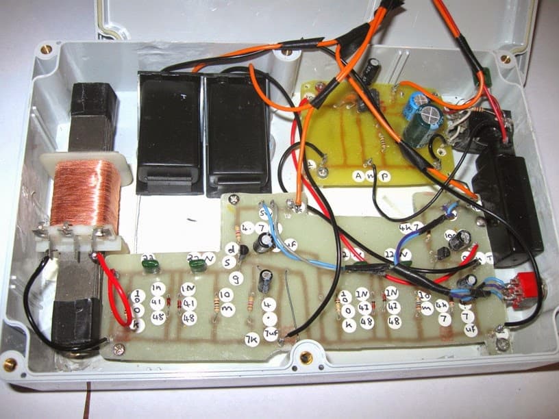
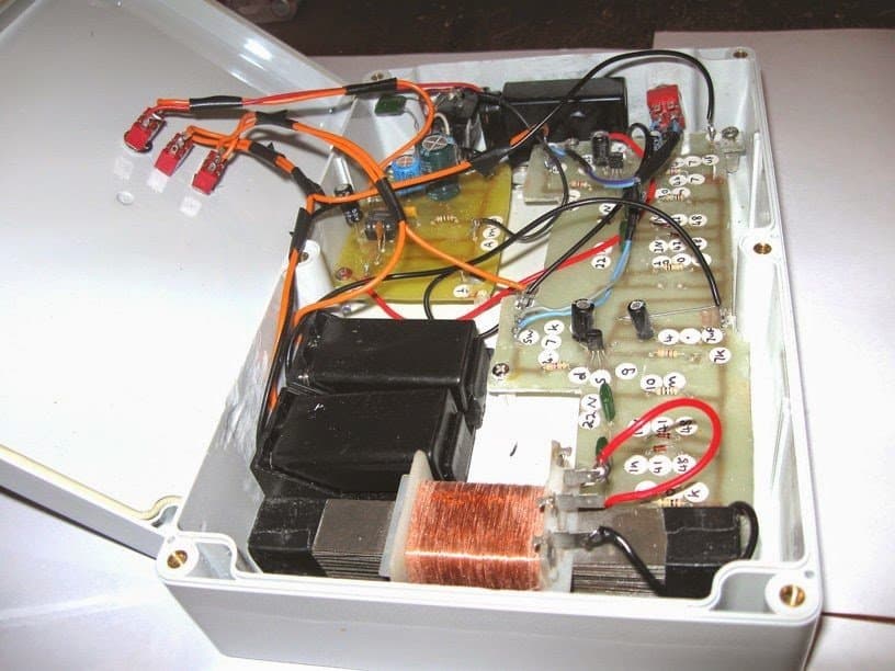
Also when I brought my handy cam close to it it sensed the em fields generated by it to here's some pictures of my vlf receiver circuit neatly installed.
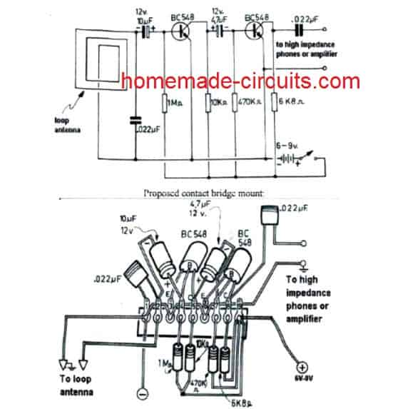
Now I've emailed you ages ago a single stage version I found on the net this is my old double stage version.
It's 2 in one and the coil is an electric shaver coil with transformer iron pieces trimmed and shoved in to concentrate the EM flux for a stronger signal.
And like my other one I made some time ago this one can sense the em pulses from a ticking analogue watch over a foot away so imagine a UFO or underground installation.
This circuit doubled up sensitivity nicely and even some other thing I do not yet know.
The circuit has 2x vlf receivers linked and an audio amp and powered each section by a separate 9 volts nimh battery so 3 batteries are used and ones for the lm386 audio amp section.
The original site on the net which I originally found this on says you can get more sensitivity by adding another stage so this is it .
I'm confident I may be able to push this to the limit by integrating the 30 million gain circuit into the design and hear beyond anything others may not hear


Questions & Answers
Hi , can help me please to build vlf metal discriminator with 0 distance
Sure, I will try to figure it out and let you know…
A 0-500 hz frequency detector/ monitor would be a very popular device. Input for variable sources ie contact probe/ antenna would be ideal. Can you do something like this?
I think the first circuit should be able to detect frequencies within the 0-500Hz range.
Hi Swagatam,
Do you have 36khz rf detector circuit which can be used for signaling loop cable??
Hi Krishna, do want the detector to be contactless or can there be a contact with the 36kHz source?
Hi Swagatam,
I would like to make a very simple detector that just give a beep (continuous) when a signal from this PEMF therapy mat is present: OMI Pads (3-99 Hz): 220 microtesla; Waveform: sinus. Powered by DC power supply.
(https://www.oxfordmedicals.com/omi-pads-pulsed-electromagnetic-field-therapy-full-body-mat.html)
The most important frequency range is up to 30Hz.
Thanks in advance!
Best Regards, Lars, Trondheim, Norway
Hi Lars,
let me figure it out, if I find a solution will update the design for you soon.
I have a commercial toner that I use to find wires, but in the circumstances that I use it the ~ 1KHz leaks into other circuits. I need an ideally tunable transmitter and receiver that I could hold about 25 cm. from the wire and get a signal. I think from .1 – .7 KHz would probably work. I see circuits for transmitters, but yours is the first receiver. What would you charge to prototype this?
I have a general purpose RF detector, but it can’t be adjusted for detecting specific frequencies.
https://www.homemade-circuits.com/bug-detector-circuit-rf-sniffer-circuit/
Would you assist me in building a very low frequency ELF detector?
I am trying to do research on transverse EMF waves in the air to detect resonant frequencies that are biologically significant. You might reference this article: http://www.miklagaard.com/wp-content/uploads/PDF-Air1.pdf
For instance, the resonant frequency of pure water is 4.50 HZ
PODE ENVIAR MEU EMAIL , ESQUEMA COMPLETO E PCB ?
AGRADECO
Hello,
Do you think that this could be used as the sensing end of an extremely high Q, LC tank circuit which has a resonant frequency around 63.2 kHz. The tank’s resonant frequency needs to be determined, and it’s pulsed input frequency matched before it has any pulsed power sent to it as, off frequency; it draws too much current for the rest of the circuitry. I’m planning on using single “pinging” signals to the tank in order to determine what it’s natural resonant frequency is before it is turned on for continuous operation.
Thank you in advance for any help you can send to me on this.
Hello Scott, I am really sorry I do not have much idea regarding this concept since it was investigated by another author…
Hi I need to buy a Vlf receiver if you have please
Hi, I am sorry I don't manufacture kits.
OK thanks, it was designed by some other hobbyist, so may be he'll take a note of it and correct it accordingly.
hello! I saw on the schematic in s1-v1 is wrong! and the q1 q2 lm 386 pin2 0v & gnd?
regards>zarkinos from greece!
V1 appears shorted at R1 path.
sorry, i meant R4
The person who drew the diagram seems to have messed up with the connections, please refer to the first diagram, and make the necessary corrections accordingly