This extremely simple code lock switch circuit can be used for locking a vehicle’s ignition by typing a hidden code over the given micro switch keypads.
So now you can use this simple code lock ignition circuit for probably securing your car from a possible theft. Alternatively the circuit may be used for any application requiring security or safeguarding from external intrusions and thefts.
The Use of SCRs in the Design
SCRs are well known to all of us and we are quite familiar to the many salient features of this important active electronic component. One important feature of this device is its latching ability when operated with a DC.
Precisely when an SCR is triggered with a DC load across its anode and cathode, the device switches ON, latches and sustains the switched ON position permanently until power is switched OFF.
For the newcomers, the device SCR is explained briefly with the following points:
Called Silicon Controlled Rectifier, an SCR basically consists of three leads, the extreme right lead is the “gate”, the center one is the cathode and the extreme right lead is termed as the anode.
The cathode needs to be connected to the ground or the negative line of the circuit.
The anode is the lead which is connected to the supply voltage (either a DC or an AC) via the load which is intended to be switched by the device.
The gate is the triggering input which is triggered with a DC, for energizing the load connected at the anode of the device.
A gate trigger instantly switches the SCR, connecting the load across the supply terminals through the SCR body.
With AC as the supply across the load, the SCR remains switched ON as long as the gate is triggered with a DC.
However when a DC is used for energizing the load, the SCR becomes a single shot switching device, because it latches and keeps the load switched ON even when the gate trigger is removed.
The above feature has been effectively exploited in the present code lock circuit design, let’s learn the circuit functioning with the following instructions:
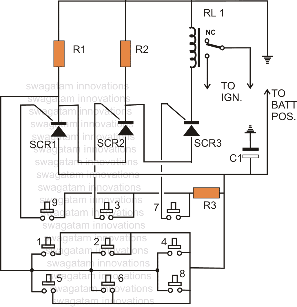
The figure shows a simple arrangement where, three SCRs are wired in conjunction with an array of ten micro switches.
Selecting the Code Numbers
As per the selected code, the particular switches are integrated with the gates of the SCRs in a given sequence as shown in the diagram.
Here, the elected code is 9, 3, 7 and these buttons are connected with the relevant SCR gates.
The other terminals of these buttons are made into a single common terminal, which is connected with the positive supply of the circuit.
How the Code Lock Works
When the switch 9 is pressed, the gate of the first SCR is triggered; it latches via R1 which is connected as the load for SCR1. This SCR also conecys the anode of SCR 2 with the negative and puts it on a standby condition.
Pressing button 3 triggers the gate of SCR2 which instantly latches with the load R2 and via the path provided by SCR1. This action connects the anode of SCR3 with the negative supply and in turn clamps SCR3 into an alert position.
Finally when button no. 7 is pressed, SCR 3 latches via the path provided by the SCR2 and in the course switches ON the relay which forms the load of SCR3.
The contacts of the relay which is possibly connected with the ignition of the vehicle become active so that the vehicle can be now started with the ignition key.
The rest of the switches other than the ones which are selected as the codes may be rigged with the positive supply, so that when an intruder tries his luck by randomly pressing the codes, only succeeds in breaking a possible combination every time it accidentally switches any of the remaining buttons.
Parts List
Parts required for making this simple code lock switch
- R1, R2, R3 = 1K,
- R3 = 470 Ohms,
- C1 = 100uF/25V,
- SCR1,2,3 = BT169,
- RL1 = relay 12 volts, 400 Ohms, SPDT
- Keyboard = 10nos. micro switch bank
Questions & Answers
Dear Swagatam,
Good day…
i would like to ask if we can determine the terminals of a triac using multimeter?meaning without any idea where’s the gate,main terminal 1 & 2 can we locate it using multimeter?
thank you
best regard,
erick
Dear Roderick,
As far as I can remember, the gate and MT2 will show continuity in meter, once these two pins are identified, the 3rd pin can be assumed to be MT1, however I am not sure how exactly gate/MT1 may be traced individually, for this you can check the continuity across these pin if you find reading to be polarized then distinguishing the gate/MT1 could become easier.
Dear Swagatam,
Im interested on your Code Lock Circuit. Infact ive tried to make the circuit using 2n5064 scr.However if i try to press the 3 switch by not following the right sequence like i press 3,7,9 it will not trigger the relay.however after pressing 9,when i press 7 again the relay trigger.Meaning when i press 3,7,9 then 7 the relay trigger..Im worried because if ever someone can press the number that i use as a code many times even in not right order there is a tendency that the relay will trigger .Then by the way,what is the use of capacitor in the circuit and other switches because when i try to press the other switch nothing happen…Are these switches act as a reset button/switch?
Please help…
Best regard,
Erick
Hi Erick, appreciate your interest, however what you are saying cannot happen, unless there’s a fault in your connections.
when you press 9, SCR1 will get latched, that’s fine.
But subsequently pressing 7 the relay cannot trigger because SCR2 is not latched yet, to trigger the relay SCR2 and SCR3 together must get latched.
The circuit is foolproof and will trigger only when the correct sequence is applied.
Yes the other button are for resetting the SCRs.
Please re-check your circuit connections carefully!
Dear Swagatam,
thank you for the fast reply..indeed the circuit is really clear since i know how scr works thats why i was confused..what is the right voltage and ampere ratings of the supply of this circuit?
Thanks Roderick,
the voltage is not critical with respect to the SCRs, it just has to match the relay coil voltage, if the relay is 12V rated then the supply should be also a 12V.
….the capacitor is for filtering possible voltage spikes, it is not crucial and can be ignored…
Sir .
when i enter the code and hold down all the buttons then it works or even when i press first and the last code digit button the relay turn on and after releasing the button the relay turn off.how to remove this fault?
Syed, that should not happen, something may be wrong with the connections, please check it carefully.
If the relay is not holding it means the scr conduction is breaking somewhere.
If one of the scr conduction breaks all scr conduction will break.
another problem could be the relay voltage, since each scr will drop 0.7V on its way the final voltage to the relay would be 12 – 2.1 = 9.9V which could be insufficient for a 12V relay especially if its coil resistance is high
try a 9V relay with a 12V supply.
Sir for 5v.
what will be the value of R1,R2 and R3?
Half of the value mentioned above or other?
Syed, only the relay will need to be changed accordingly, rest everything may be kept as is.
Is there any another SCR that can be used? BT169 is not available in our area.
you can inquire with your spare part dealer about any suitable equivalent which may be available with him.
sir how can i increase the number of code you have only used three switches but i want to use five. Kindly tell me the way how to do it.
isolate one of the lower switches and configure it with another SCR stage (make scr3, R3) as done with the switches no. 9,3,7