This simple circuit tester probe can be used for detecting short circuits, abnormal resistance conditions, continuity breaks etc inside an assembled circuit board or a PCB. The indication will be through an audible buzzer sound or an LED illumination.
The described designs are all extremely safe to use even with PCBs that may have highly sensitive or vulnerable electronic components.
Passive testing of your electronic circuit PCB may appear to be a simple job. All you require is a Ohm meter.
However, using an Ohm meter for checking boards with semiconductors may not be generally such a wise decision. The output currents from the meter could possibly harm semiconductor junctions.
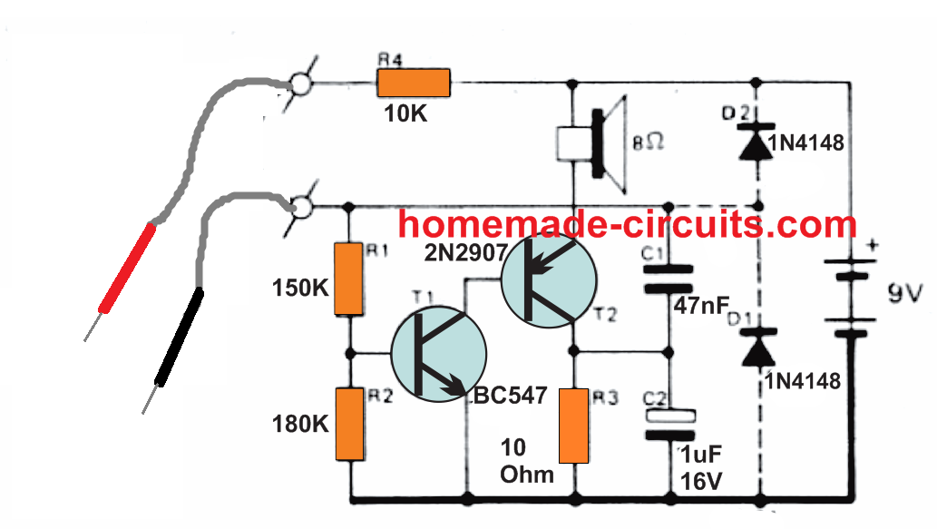
The first circuit I have explained below which is a transistor based tester is very easy to develop, and has the good safety advantage since its probes produce not more than 50 µA to the circuit which is being tested.
Therefore it can be safely used for troubleshooting the majority of standard IC's and semiconductor such as MOS-components.
The test result 'indicator' is actually in the form of a little loud- speaker, to ensure that at the time of testing, it isn't essential to keep diverting your eyes towards the testing device, rather than the circuit board.
The transistor T1 and T2 work like a basic voltage-controlled low frequency oscillator, which has a loudspeaker as the load. The oscillator frequency depends on C1, R1, R4 and the resistance value of the external resistive load across the probes that is being measured. Resistor R3 becomes the collector resistance of T2; C2 acts like a low frequency decoupling for R3.
As explained previously, the tester will never harm a circuit under test; however, oppositely, it may be important to include diodes D1 and D2 to ensure that the potential from circuit under test doesn't cause harm to the tester unit.
Given that there isn't any power association between the testing probes, the circuit is not going to pull any current. Battery life as a result may be almost comparable to its shelf life
Using Op Amp
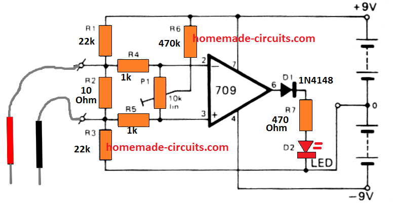
Another highly accurate and safe circuit board tester and fault tracer is described in the following paragraphs. It is an op amp based design which makes the operation even more accurate than the previous transistorized version.
As already discussed, while testing a circuit connection continuity by using an standard ohmmeter, often there is the risk that resistors, semiconductors etc. engaged in the testing, may result in giving false readings. In addition the current or voltage from the meter can on occasion cause destruction of the circuit parts.
Using this op amp based circuit tester concept as shown above, all these drawbacks are safely eliminated.
The tester creates a resistance of no more than 1 ohm across its probes whenever the probes happen to interconnect two points over a circuit board.
Also, since the voltage used by the tetser is hardly 2 mV, implies that no diode, IC or any such vulnerable component get involved in the results during the testing procedure.
The highest magnitude of current that may appear across the test probes on the board which is being tested will be 200 pA, which looks too modest to cause any sort of issues to the PCB under test. The test result indication is through a LED.
If the unit is build to fit inside a pen like enclosure then it can become extremely handy and the whole unit can be used as the one of the probes, whie the other probes is clipped somewhere else on the board.
One drawback is the requiremenet of two 9V cells as the power supply for the unit.
The shown preset is used for adjusting the output offset of the op amp.
The user will have to adjust the preset P1 such that the LED just lights up when the probes ends are shorted. Conversely, the LED must instantly shut off when the probes are opened.
This will set up the circuit to illuminate the LED only when the probes encounter an almost short like condition on the PB under test.
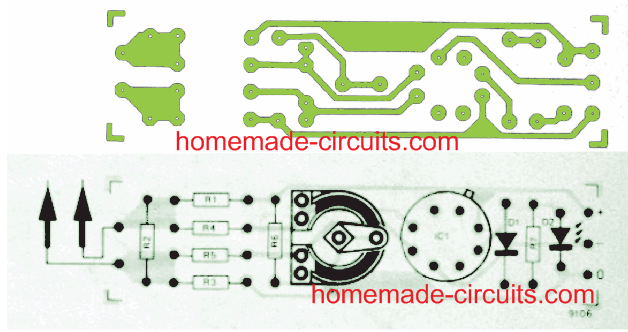
A very compact and sleek PCB is designed for this tiny little PCB tester, which can be studied through the following diagrams.


Questions & Answers
Just built the op-amp short circuit locator and working well…I am now attempting to a more complicated build using arduino microcontroller. Could you please elaborate on the method of using 2 op-amps and one 9-volt battery….are there any schematics for that configuration?
Glad you could build it successfully, yes, two opamps and one 9v battery is possible. I will try to update the diagram soon in the above article.
So I’m looking to make the op amp tester. Diagram I but need to know first what p1 is or means? As well as what the 79 triangle is. And lastly the lines that connect arethey running threw, connecting ? I will be more clear with the response I get as well as I will try to download the picture and upload with circling which areas I mean about lines running threw.
Sure, I will try to clear your doubts.
P1 is a variable resistor called preset or a trimpot.
The 709 triangle is the op amp, you can use a 741 as well instead of 709.
The running through lines are not connected. The connected points are specifically represented by the black spots or the round circles.
Using op amp for pcb boards to find faults there’s no parts list to tell me exactly what I need to use to build that circuit. I would like to build it
Unfortunately the parts labels are quite faded on the PCB, and it is difficult to restore them back. With little effort you can perhaps trace the tracks and find which components needs to be inserted on the respective pads.
Hi – Trying to make your Op Amp version and need help.
1) is P1 – a POT?
Hi, P1 is a preset or a trimpot, a PCB mounted variable resistor
is the second circuit with the red led using two 9 volt dc battery´s
yes, it uses two batteries. But you can create the same effect artificially using another op amp, with a single 9V battery
ok my friend thk´s and heat´s up with the Virus
Sir please, does the op amp detects short circuit, wrong connection or fault (eg burnt capacitors ) in the PCB or any circuit you are testing or trouble shooting.
Valentine, yes the op amp will detect only short circuit conditions, and illuminate the LED.
Hey my friend family ok , and your self to
Thanks friend, we are all safe, trust you are also safe.
do they realy work ,I make a power supply around tree weaks ago did not work ,it was not from Your web site, talking about the probes testers
Yes Sir keeping eye open washing the hand´s a lot , take care
Yes the above circuits are tested and they will work to locate shorts or extreme low resistances on PCBs.