Crystal oscillators are electronics devices that produce stable, accurate, and repeated signals that are widely employed in a wide range of electronic applications. Because of their great stability, precision, and low noise, they have become a crucial component in many electronic circuits. In this post, we will look at how crystal oscillators function, as well as their many varieties, applications, advantages, and disadvantages.
Working Principle:
A crystal oscillator is a circuit that generates a constant and exact frequency by utilising the piezoelectric action of a quartz crystal.
The piezoelectric effect is a phenomena in which a material can create an electric field whenever mechanical stress is applied to it or oscillate when an electric field is applied to it.
In the case of a crystal oscillator, the resonator is a quartz crystal. Whenever an alternating voltage is supplied to the crystal, it resonates at a specified frequency defined by the crystal's physical dimensions.
A crystal oscillator circuit is made up of an amplifier and a feedback network. The quartz crystal is connected in a feedback loop, while the amplifier output is fed back to the crystal.
Here, the crystal works as a resonator, and the feedback network enables the intended feedback to maintain the oscillation at the resonance frequency of the crystal.
The output signal from the crystal oscillator is a sine wave having a frequency set by the crystal's resonance frequency.
Types of Crystal Oscillators:
There are several types of crystal oscillators, including:
Pierce Oscillator: The most popular type of crystal oscillator is the Pierce oscillator. It is made up of a quartz crystal and a feedback network that gives the necessary phase change to keep the oscillation running. Generally, the feedback system includes two capacitors and a resistor.
Colpitts Oscillator: Another form of crystal oscillator is the Colpitts oscillator. A quartz crystal, two capacitors, and two inductors make up the circuit. The feedback network provides the required phase change to keep the oscillation going.
Clapp Oscillator: The Clapp oscillator is a modified version of the Colpitts oscillator. It includes an additional capacitor in the feedback network, which provides additional stability and reduces the effect of parasitic capacitance.
Butler Oscillator: The Butler oscillator is a high-frequency crystal oscillator commonly used in radio frequency applications. The fundamental phase shift from a Butler oscillator is created by a feedback network, a crystal, and an amplifier.
Advantages of Crystal Oscillators:
High Accuracy: Crystal oscillators ensure high accuracy with their output results. This accuracy is essential for precise timing applications.
Stable Output: Crystal oscillators ensure that its output is always stable. This stability is crucial for high-frequency applications.
Low Noise: Crystal oscillators ensure that its signals have very low noise. This low noise output becomes crucial for sensitive electronic applications.
Low Power Consumption: Crystal oscillators ensure that their power consumption is minimal. This feature essential for battery-powered devices.
Disadvantages of Crystal Oscillators:
Expensive: Crystal oscillators are sometimes quite expensive compared to other normal types of oscillators.
Limited Frequency Range: Crystal oscillators may often have a limited frequency range, which may not be suitable for quite a few applications.
Susceptible to Shock and Vibration: Crystal oscillators are sensitive to shock and vibration, this can affect their accuracy and stability.
Sensitivity to Temperature: Crystal oscillators are susceptible to temperature changes. This drawback can affect their frequency stability. In order to overcome this, temperature compensation techniques must be employed.
Applications of Crystal Oscillators:
Several electronic applications employ crystal oscillators, due to their following advantages:
Timebase Generators: Due to their excellent precision and stability, crystal oscillators are frequently employed as a timebase for clocks and timing circuits.
Microcontrollers: To synchronize their internal activities, microcontrollers employ crystal oscillators as a clock source.
Communication Systems: Crystal oscillators are used to create the carrier signal in communication systems including radio and television transmitters and receivers.
Signal Generators: Signal generators produce signals with various frequencies and waveforms using crystal oscillators.
Crystal Circuit using Colpitts Oscillator
A simple-to-build crystal Colpitts oscillator in the range of 1 to 20 MHz may be seen in the figure below. It is built around a parallel-operated crystal and a vintage germanium NPN bipolar transistor.
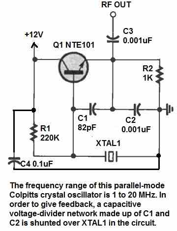
The capacitive voltage -divider network, which is made up of C1 and C2, is efficiently shunted across the crystal XTAL1 and functions as the feedback network that causes the circuit to oscillate.
Capacitors C1 and C2 must to be NPO ceramic disc or silvered mica versions. For RF, the transistor's collector is bypassed to ground, but it is actually at a DC voltage of +5 to +15 volts. A 0.001uF capacitor, C3, is used to extract output from the transistor's emitter.
Parallel Mode Crystal Oscillator Circuit
The next design depicts a silicon transistor-based variant of the previous circuit.
This particular parallel-mode oscillator can function across a little wider frequency range.
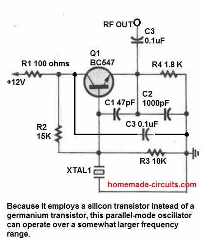
Additionally, some contend that oscillators utilizing silicon transistors may start oscillating more consistently than those using germanium semiconductors (like the one in the above figure).
But, the author has tested both circuits and has not encountered any startup issues. You can test out different values for the bias resistors and feedback capacitors if you find an issue (C1 and C2).
Fundamental Mode Crystal Oscillator
The next circuit is intended to run between 500 kHz and 20 MHz, according to the capacitance values utilized in the feedback circuit using C2 and C3.
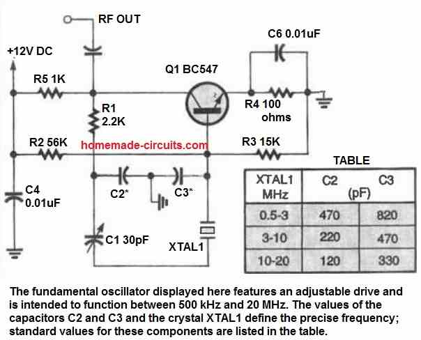
Based on the crystal being utilized, standard values for those capacitors are shown in the adjoining table. To tune the working frequency exactly where it needs to be, a frequency-trimming capacitor (C1) is employed.
If the feedback resistor (R1) is replaced with one of a higher value, the circuit will function with more stability and less harmonic distortion.
Some investigation can determine the precise value. That strategy should only be applied, though, when the oscillator is functioning freely. If the value of R1 is too high, there may be an issue if it is keyed or somehow switched on and off.
When the resistor value is higher, the oscillator will increase to its maximum output amplitude more quickly than when it is lower. However, using a resistor with a value less than 2200 ohms could result in the crystal being overdriven.
Fundamental Mode, 20 MHz Crystal Oscillator
The figure below illustrates a basic frequency oscillator circuit with a 10 parts per million (PPM) frequency stability. The transistor's emitter and the junction of the capacitor potential divider feedback network are coupled to the crystal in this circuit.
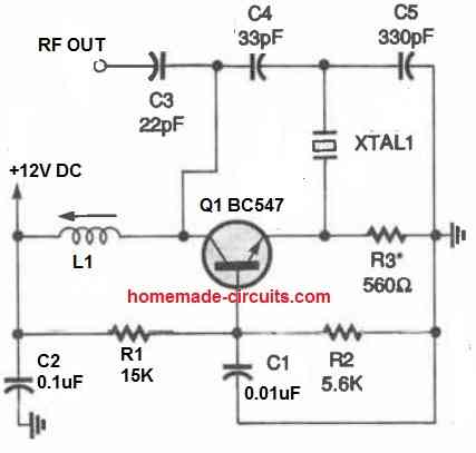
Crystals with both parallel and series modes can be employed. By experimenting, the feedback capacitor ratio may be altered for the optimal (greatest stability) performance.
R3 may be changed to any resistor with an ohmic value between 100 and 1000 to change the output level of the crystal, XTAL1. The stability is improved and crystal dissipation is decreased with a lower value of R3.
C4 resonates inductor L1 to the crystal frequency. It is virtually always feasible to find a configuration near resonance where the crystal oscillator will activate consistently each time it is switched ON. If L1 coil is wrongly tuned or built, the circuit will simply not start.
Pierce Crystal Oscillator Circuit
The next crystal oscillator depicts a Pierce-oscillator circuit. The circuit contains a crystal interconnected between the active device's output and input, similar to all Pierce oscillators.
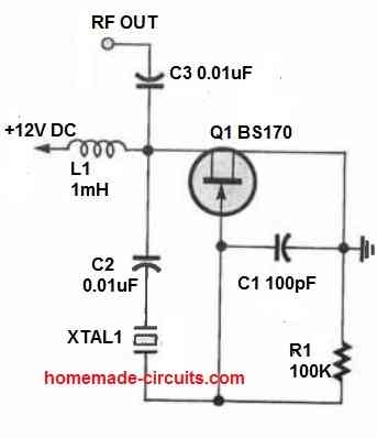
The crystal is linked between the drain and gate of the circuit because a JFET is being utilized, as opposed to the collector and base of a bipolar transistor.
A DC-blocking function is performed by the capacitor (C2) connected in series with the crystal. Although this capacitor can be removed in certain low voltage transistor designs, it is necessary for our purpose.
Unijunction Crystal Oscillator
Our next design, shown in the following figure, is an odd 100 kHz oscillator constructed around a unijunction transistor (UJT).
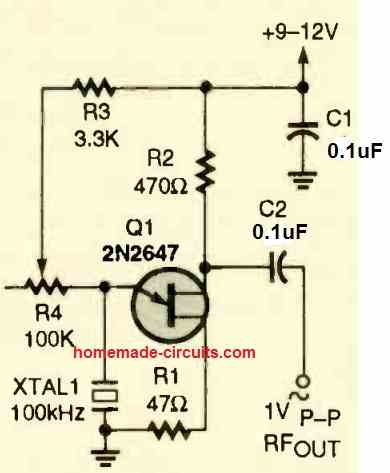
Crystal XTAL1 regulates the working frequency of this circuit. The output of that straightforward crystal-controlled oscillator may be sent to a divider counter to provide a steady lower-frequency output for use as a clock generator or employed as a marker generator to align the analogue dial of a communications receiver.
The majority of RC timing circuits incorporated in UJT-based oscillators are used to regulate the oscillator's frequency.
For many applications where frequency stability is not a major concern, that approach works wonderfully. The cheapest and easiest solution is to use a quartz crystal where frequency stability is crucial.
To get an excellent sinewave, the above oscillator output will need to be tweaked. You will want an oscilloscope for this.
Simply attach the oscilloscope to the circuit's output and tweak R4 to get the waveform that looks the cleanest. If an oscilloscope is not available, good results can be obtained using an AM radio.
Just switch on the AM radio and adjust the dial to a band that is at the low-frequency part of the spectrum.
Place the radio close to the oscillator, and then tweak R4 until you hear a heterodyne (beat signal).
455 kHz Crystal Oscillator Circuit
This straightforward circuit allows for the utilization of a standard 455 kHz ceramic IF resonator as the primary component responsible for determining the frequency in an alignment oscillator or BFO.
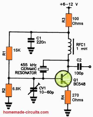
The resonator employed here is of the two-terminal type, specifically designed to act as a frequency-dependent bypass within an amplifier stage.
In this configuration, it is connected between the collector and base of a transistor amplifier stage to provide feedback at the resonator's designated frequency.
To accommodate BFO applications, the trimmer component (CV1) allows for slight frequency adjustment.
To introduce modulation, audio can be capacitively coupled into the emitter of transistor Q1 through R4, with modulation originating from a low impedance source.
Q1 can be replaced with various transistor options to suit different requirements.
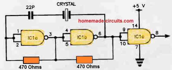
Crystal Oscillator using NAND Gates
This circuit is designed to fulfill the requirements of applications that involve toggling a crystal oscillator using a switch and/or digital signal.
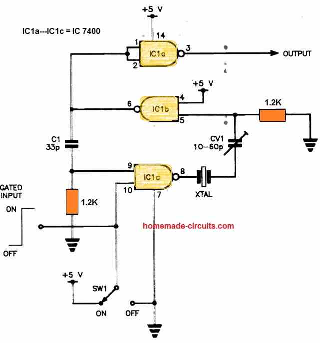
The crystal oscillator is constructed using two gates from a 7400 quad NAND package. In case frequency trimming is necessary, CV1 is included.
Alternatively, a 33p capacitor can be used as a replacement.
The output is buffered by IC1a.
By setting one input of IC1c to a low state, the oscillator can be turned off, while setting it to a high state will turn it on.
Another Simple TTL NAND Gate Crystal Oscillator Circuit
Crystal oscillators implemented with TTL logic frequently encounter issues such as unreliable initialization, intermittent oscillation, and various other problems. However, the circuit presented here overcomes these challenges consistently.
To construct this circuit, a pair of two-input NAND gates are connected consecutively to form a non-inverting buffer.
Two 470 Ohm resistors are employed to establish bias between the output and input of each stage.
By operating at its resonant frequency, the crystal ensures zero phase reversal, enabling positive feedback and oscillation exclusively at that specific frequency.
Additionally, an additional gate serves as a buffer.
It is important to note that this circuit is compatible with various logic families including the 74-series, 74LS-, and 74HCT series logic.
Conclusion:
In conclusion, because of their excellent stability, precision, and low noise, crystal oscillators are a crucial part of many electronic circuits. They are extensively utilised in several systems, such as signal generators, microcontrollers, communication systems, and clocks and timing circuits.
Despite several drawbacks including high cost and sensitivity to shock, vibration, and temperature, they are still the favoured option for many electronic applications because of the benefits they provide. Crystal oscillators continue to play a significant part in current electronic devices as technology develops, and their significance is anticipated to grow in the future.

Questions & Answers
The ckt employed very few components and input voltage of 12v. There are many ckts available all over the Internet but they aren’t simple or use least components. Awaiting your suggestions!
A very Good morning Sirji!
I had made a 8MHz crystal oscillator using just single 2n3904 ckt taken from some online source. But the problem is that the output is just 1.5mV. I need to increase it. I searched over the Internet but could not find any ckt that employs two transistor oscillator with one or both using 2N3904 BJTs. Do you have any suggestions?
And Merry Christmas to you! Sirji !!
Good Morning Maddy, and Wish you too a Merry Christmas!!
I think you should try the designs presented in the following article, this should fulfill your requirement:
https://www.homemade-circuits.com/simple-crystal-tester-circuit/
I would like to build a voltage controlled crystal oscillator (VCXO) that it can be used in a phase locked loop. How could I apply a control voltage to tweak the frequency of the oscillator?
Sorry, it looks difficult to me. Not sure how a crystal oscillator can be combined with PLL to form a VCO?
However, I have a few VCO circuits in the following link, maybe you can find some way to add a PLL and a crystal with it:
https://www.homemade-circuits.com/voltage-controlled-oscillator-circuit/
per amplificare il segnale per tali schemi ?
Hello Swagatam,
Are your articles available in pdf format? They do not print well off the web page.
Thanks,
Pete
Hello Peter, there are many online sources which will convert any webpage to pdf for you. You can search the same online and get any URL converted to pdf.
i was searching 40mhz crystall oscillator and found a ckt https://forum.allaboutcircuits.com/threads/questions-about-crystal-oscillator-circuit.114837/ …
i applied ckt on bread board and measured on dso …the output had only 800mv ac component of 40mhz while other part was dc component of around 4v . i applied Vcc of 5v . what i want is atleast 4v peak to peak and also 9v peak to peak if Vcc is 9V …waiting for quick reply
You must use another transistor stage for getting the required peak to peak.