In this article I have explained how to make a simple 2-step Arduino programmable timer circuit, which can be used to switch an electrical load ON/OFF with independently adjustable ON and OFF timings.
For example if you want a light to remain ON for 24 hours and OFF for 2 hours, you can simply do this through a quick modification in the program code. In the same way you can customize the output timings to any other desired set of time intervals by changing the code appropriately.
You just have to compile and upload the following code to your Arduino board and start the timer function as per your specific application needs.
Program Code
void setup(){
pinMode(13, OUTPUT);
}
void loop(){

digitalWrite(13, HIGH);
delay(86400000);
digitalWrite(13, LOW);
delay(3600000);
}
In the above example code the lines delay(86400000); and delay(3600000); determine the output ON and OFF delay time intervals respectively, in milliseconds. Here, the figure 86400000 milliseconds corresponds to 24 hours, while 3600000 exhibits 1 hour delay.
You can customize these two values as per your personal preference to get the required output delays.
Once setup and powered, the Arduino will continue switching between the two step ON/OFF timing sequence. as long as power remains applied to the system.
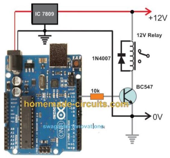
Circuit Diagram
The complete circuit diagram along with the Arduino connections can be witnessed in the following diagram:
Advanced Programmable Timer Version
Here is the most advanced version of the above programmable timer code using non-blocking millis() technique so Arduino remains fully responsive and can do other tasks while managing the timer.
Full Code
const int outputPin = 13;

unsigned long onTime = 86400000;   // ON time in milliseconds (24 hours)
unsigned long offTime = 3600000;   // OFF time in milliseconds (1 hour)

unsigned long previousMillis = 0;
bool outputState = false;

void setup() {
  pinMode(outputPin, OUTPUT);
  Serial.begin(9600);
}

void loop() {
  unsigned long currentMillis = millis();

  if (outputState == false) {
    // Currently OFF, check if it's time to turn ON
    if (currentMillis - previousMillis >= offTime) {
      outputState = true;
      digitalWrite(outputPin, HIGH);
      previousMillis = currentMillis;
      Serial.println("Output turned ON");
    }
  }
  else {
    // Currently ON, check if it's time to turn OFF
    if (currentMillis - previousMillis >= onTime) {
      outputState = false;
      digitalWrite(outputPin, LOW);
      previousMillis = currentMillis;
      Serial.println("Output turned OFF");
    }
  }

  // You can do other tasks here without being blocked by delay()
}
Full Explanation
Now, let us understand the above most advanced programmable timer using Arduino that works without blocking the processor so that we can do other things while timer is running.
This is very useful because using delay() makes Arduino freeze and do nothing else.
First, we define some variables like this:
outputpin = 13 this is the pin number where we will connect the load or led or anything we want to control
ontime = 86400000 this is on duration in milliseconds 24 hours
offtime = 3600000 this is off duration in milliseconds 1 hour
previousmillis = 0 this will remember last time when we switched state
outputstate = false initially we start with output off
in setup() function, we do this:
We set pin 13 as output by calling pinmode(outputpin, output)
We start serial communication by serial.
begin(9600) so that we can see debug messages on serial monitor
Now in loop(), we read current time from arduino with currentmillis = millis().
Then, we do check like this:
When output is off outputstate == false
We check that if currentmillis - previousmillis >= offtime, then off time has passed, then we turn on output by digitalwrite(outputpin, high)
We set outputstate = true and previousmillis = currentmillis
Also, we print "output turned on" to serial monitor
When output is on outputstate == true, we check that if currentmillis - previousmillis >= ontime then on time has passed, then we turn off output by digitalwrite(outputpin, low).
We set outputstate = false and previousmillis = currentmillis.
Also, we print "output turned off" to serial monitor
Now we can do other tasks without Arduino being stuck or frozen
This method is much better than using delay() because delay() just stops everything and Arduino cannot do anything else while waiting.
But with millis() method, arduino stays alive and responsive.
So now we can read sensors, send serial data, or communicate with other devices without any problem.
You can change ontime or offtime value at the top
For example:
ontime = 60000 on for 1 minute
offtime = 300000 off for 5 minutes
You just change the number and it works that is all.
If you want us to make this timer adjustable in run-time by serial monitor or save settings in eeprom then we can do that too.
Then you will not need to change code again and again.
This is now the most advanced super flexible non-blocking timer you can ever make on Arduino.
It works reliably and stays ready for more functions in parallel.
Arduino One-Shot Timer Circuit
If you don't want the timer to loop through the two step timer, instead want the timer to be a one-shot type, which will switch OFF permanently after the set delay, you can apply the following code:
Full Code:
int led = 13

unsigned long delay_time = 10000  // 10 seconds
unsigned long delay_start = 0  // the time the delay started
bool delay_running = false  // true if still waiting for delay to finish

void setup()
{
  pinmode(led, output)  // we initialize the digital pin as output
  digitalwrite(led, high)  // now we turn led on

  delay_start = millis()  // we record current time as start of delay
  delay_running = true  // we mark that delay is running
}

void loop()
{
  unsigned long current_millis = millis()  // we read current time every loop

  if delay_running == true and (current_millis - delay_start) >= delay_time
  {
    delay_running = false  // now delay finished, this is single shot, so only happens once
    digitalwrite(led, low)  // we turn led off
  }

  // now, we can do other tasks here without being blocked by delay
}
Explanation
Now let us explain this improved code for the one-shot timer step by step.
First we declare variables.
led = 13 This is the pin where the LED is connected on the Arduino board.
delay_time = 10000 This is how long we want to keep the LED on in milliseconds; that is 10 seconds.
delay_start = 0 This will store the time when the delay starts.
delay_running = false This tells us if the delay is running or finished.
In the setup() function, we do this.
We set pin 13 as output by calling pinMode(led, output).
Then we turn the LED on by digitalWrite(led, high).
We record the current time by millis() into delay_start.
We set delay_running = true to mark that the delay is now running.
In the loop() function, we do this every time Arduino loops.
We read the current time from millis() into current_millis.
Then we check that if delay_running == true and (current_millis - delay_start) >= delay_time, then delay time has finished.
If that is true, then we set delay_running = false, meaning the delay finished. Then we turn the LED off by digitalWrite(led, low).
Now because we use millis() instead of delay(), Arduino never gets stuck or blocked.
So now we can add more code here to read sensors or send serial data or do other tasks while this timer is running in the background.
This method is way better than using simple delay(10000) because delay() would stop everything for 10 seconds.
But with this millis() method, Arduino keeps doing other things and remains fully responsive.
You can easily change the delay_time variable to any number you want.
for exampledelay_time = 5000 Now it will keep the LED on for 5 seconds.
delay_time = 30000; now it will keep the LED on for 30 seconds.
You just change the number and it works, that is all.
If you want us to make this timer adjustable by serial input or save the state in EEPROM so that it works even after power-off, we can do that too.
Then you will not need to change code manually every time. This is now an improved version of your programmable single-shot timer using millis(). It is reliable, non-blocking, and easy to customize.
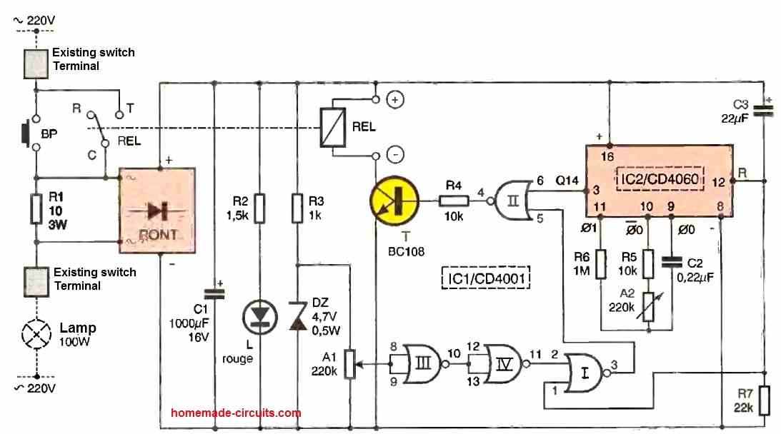
If you want a discretely designed version of an identical programmable timer circuit, you can opt for this circuit
Parts Required for the Arduino Programmable Timer Circuit
- Arduino UNO Board = 1
- IC 7809 = 1
- BC547 = 1
- 1N4007 Diode = 1
- 10k 1/4 w resistor = 1
- Relay 12V/400 ohm/SPDT/5 amp = 1
- 12V AC to DC Adapter = 1
Using EEPROM to Handle Power Cut Problems
Full Code:
#include <EEPROM.h>   // Include EEPROM library for permanent storage

// -------------------- USER SETTINGS --------------------

const int outputPin = 13;   // LED connected to pin 13

// Set your ON and OFF time here (in milliseconds)
unsigned long onTime  = 240000;   // 4 minutes ON
unsigned long offTime = 60000;    // 1 minute OFF

// -------------------- GLOBAL VARIABLES --------------------

unsigned long previousMillis = 0;   // Stores last time reference
unsigned long remainingTime = 0;    // Stores how much time is left in current state

bool outputState = false;           // false = OFF, true = ON

// EEPROM memory locations
#define STATE_ADDR 0   // Address to store ON/OFF state
#define TIME_ADDR  10  // Address to store remaining time

// --------------------------------------------------------
// Function to save current state and remaining time
// into EEPROM so it survives power failure
// --------------------------------------------------------
void saveData()
{
  EEPROM.put(STATE_ADDR, outputState);     // Store ON/OFF state
  EEPROM.put(TIME_ADDR, remainingTime);    // Store remaining time
}

// --------------------------------------------------------
// Function to load saved state and time from EEPROM
// when Arduino restarts
// --------------------------------------------------------
void loadData()
{
  EEPROM.get(STATE_ADDR, outputState);     // Read saved ON/OFF state
  EEPROM.get(TIME_ADDR, remainingTime);    // Read saved remaining time

  // Safety check:
  // If stored value is garbage or too big,
  // reset remainingTime to zero
  if (remainingTime > onTime && remainingTime > offTime)
  {
    remainingTime = 0;
  }
}

// --------------------------------------------------------
void setup()
{
  pinMode(outputPin, OUTPUT);  // Set LED pin as output
  Serial.begin(9600);          // Start serial monitor

  loadData();  // Load previous saved data from EEPROM

  // If no valid data found, start fresh
  if (remainingTime == 0)
  {
    outputState = false;       // Start from OFF
    remainingTime = offTime;   // First cycle will be OFF duration
  }

  // Apply the stored state to the LED
  digitalWrite(outputPin, outputState ? HIGH : LOW);

  // Set current millis as starting reference
  previousMillis = millis();
}

// --------------------------------------------------------
void loop()
{
  unsigned long currentMillis = millis();  // Get current running time

  // Check if required time has passed
  if (currentMillis - previousMillis >= remainingTime)
  {
    // Toggle state (ON becomes OFF, OFF becomes ON)
    outputState = !outputState;

    // Apply new state to LED
    digitalWrite(outputPin, outputState ? HIGH : LOW);

    // Load next duration based on state
    if (outputState == true)
    {
      remainingTime = onTime;   // If turned ON → load ON time
    }
    else
    {
      remainingTime = offTime;  // If turned OFF → load OFF time
    }

    // Reset time reference
    previousMillis = currentMillis;

    // Save updated state and time to EEPROM
    saveData();

    // Debug message
    Serial.println(outputState ? "Output ON" : "Output OFF");
  }

  // No delay() used → non-blocking timer
}
We made this version because power cut could mess things up, so now this one handles that.
The Normal Timer Problem
Let us say LED ON for 4 minutes. At 2 minutes power goes OFF. Now when power comes back, then timer starts again from zero, like nothing happened, so that is wrong behavior. That is the usual issue we see in our homes.
What We Changed Here
We however, store two main things inside EEPROM, since EEPROM does not forget even if power goes away.
We store:
- Current state, ON or OFF.
- Remaining time, how much still left.
So now when power comes back, then Arduino reads EEPROM first, not restarting blindly. Therefore it continues from where it stopped.
EEPROM does not erase when power is removed, so that is the key point here.
Main Variables
We have:
- onTime = time LED stays ON.
- offTime = time LED stays OFF.
- remainingTime = how much time still pending.
- outputState = whether LED is ON or OFF.
- previousMillis = reference starting point.
When First Power ON happens
If EEPROM does not contain valid stored time, then it assumes fresh start. It starts from OFF state.
It sets remainingTime = offTime. So that becomes the starting cycle.
During Normal Operation
Loop keeps checking this condition: currentMillis - previousMillis >= remainingTime
If that becomes true, then state changes. If LED was ON then it goes OFF, if it was OFF then it goes ON.
Then next duration loads, onTime or offTime. Moreover it saves new state and new remainingTime into EEPROM again. So memory always stays updated before next cycle.
During Power Failure
Let us take example. ON time = 4 minutes. At 2 minutes power goes OFF.
Since EEPROM was already updated earlier, then it already has:
outputState = ON
remainingTime = balance ON time
So now when power returns, then Arduino reads that stored data first. LED turns ON immediately, because state says ON. It continues only the leftover time, not full 4 minutes again.
After that finishes, then normal cycle continues like usual.


Questions & Answers
hi sir, sir is it possible to store the time on eprom while power off suddenly. like if timer is running for 1 hr count reached at 40mints and suddenly power off. after 5 minuts power again comes. then its start from at 45minuts or from the start its again. without battery is it possible to store or not?Plz guide
Hi Ghulam, yes that’s possible according to me, that’s exactly what the EPROM code is designed to do…
sir i tried this advance timer coding. its working but in this code no EPROM. after uploading the code led off. and then after given time its on. while led on for example for 4 minutes. and at 2 minuts switched off the power. its goes at initial stage. but i want if we want to on led for 4 minuts. at at 2 minuts power off. then after 1 minites power on. led remain on for remmaining 1 minuts. plz give me coding for this logic. thanks a lot
Hi Ghulam, which code are you referring to, is the last code in the above article, let me know I will try to modify it accordingly…
Thank younsor, this is the code…
const int outputPin = 13;
unsigned long onTime = 86400000; // ON time in milliseconds (24 hours)
unsigned long offTime = 3600000; // OFF time in milliseconds (1 hour)
unsigned long previousMillis = 0;
bool outputState = false;
void setup() {
pinMode(outputPin, OUTPUT);
Serial.begin(9600);
}
void loop() {
unsigned long currentMillis = millis();
if (outputState == false) {
// Currently OFF, check if it’s time to turn ON
if (currentMillis – previousMillis >= offTime) {
outputState = true;
digitalWrite(outputPin, HIGH);
previousMillis = currentMillis;
Serial.println(“Output turned ON”);
}
}
else {
// Currently ON, check if it’s time to turn OFF
if (currentMillis – previousMillis >= onTime) {
outputState = false;
digitalWrite(outputPin, LOW);
previousMillis = currentMillis;
Serial.println(“Output turned OFF”);
}
}
// You can do other tasks here without being blocked by delay()
}
Thank you Ghulam, Please try this code: // Include EEPROM library for permanent storage
#include
// ——————– USER SETTINGS ——————–
const int outputPin = 13; // LED connected to pin 13
// Set your ON and OFF time here (in milliseconds)
unsigned long onTime = 240000; // 4 minutes ON
unsigned long offTime = 60000; // 1 minute OFF
// ——————– GLOBAL VARIABLES ——————–
unsigned long previousMillis = 0; // Stores last time reference
unsigned long remainingTime = 0; // Stores how much time is left in current state
bool outputState = false; // false = OFF, true = ON
// EEPROM memory locations
#define STATE_ADDR 0 // Address to store ON/OFF state
#define TIME_ADDR 10 // Address to store remaining time
// ——————————————————–
// Function to save current state and remaining time
// into EEPROM so it survives power failure
// ——————————————————–
void saveData()
{
EEPROM.put(STATE_ADDR, outputState); // Store ON/OFF state
EEPROM.put(TIME_ADDR, remainingTime); // Store remaining time
}
// ——————————————————–
// Function to load saved state and time from EEPROM
// when Arduino restarts
// ——————————————————–
void loadData()
{
EEPROM.get(STATE_ADDR, outputState); // Read saved ON/OFF state
EEPROM.get(TIME_ADDR, remainingTime); // Read saved remaining time
// Safety check:
// If stored value is garbage or too big,
// reset remainingTime to zero
if (remainingTime > onTime && remainingTime > offTime)
{
remainingTime = 0;
}
}
// ——————————————————–
void setup()
{
pinMode(outputPin, OUTPUT); // Set LED pin as output
Serial.begin(9600); // Start serial monitor
loadData(); // Load previous saved data from EEPROM
// If no valid data found, start fresh
if (remainingTime == 0)
{
outputState = false; // Start from OFF
remainingTime = offTime; // First cycle will be OFF duration
}
// Apply the stored state to the LED
digitalWrite(outputPin, outputState ? HIGH : LOW);
// Set current millis as starting reference
previousMillis = millis();
}
// ——————————————————–
void loop()
{
unsigned long currentMillis = millis(); // Get current running time
// Check if required time has passed
if (currentMillis – previousMillis >= remainingTime)
{
// Toggle state (ON becomes OFF, OFF becomes ON)
outputState = !outputState;
// Apply new state to LED
digitalWrite(outputPin, outputState ? HIGH : LOW);
// Load next duration based on state
if (outputState == true)
{
remainingTime = onTime; // If turned ON → load ON time
}
else
{
remainingTime = offTime; // If turned OFF → load OFF time
}
// Reset time reference
previousMillis = currentMillis;
// Save updated state and time to EEPROM
saveData();
// Debug message
Serial.println(outputState ? “Output ON” : “Output OFF”);
}
// No delay() used → non-blocking timer
}
sir start of the code #include was missing. i added and now its working but while we power off at 30 sec or minute. and connect after 20 sec or so on…led status is ok like if that time power was on again connect power led remain on. but time start from the begining. is it possible time not stop. EEPROM save the running time and on and off at deceided time. once power off if that time led off. inwhile time is going on and reached to on time led should be on….hope you understand me….thanks for your kind cooperation plz
Hi Ghulam, What you are expecting is not possible…
If you want the timer to continue running even during power failure and automatically switch ON/OFF at the correct scheduled time after power returns, then you must use a Real Time Clock (RTC) module like DS3231. The RTC has its own backup battery and keeps tracking real time even when the Arduino is OFF.
So for actual “time never stops” operation, RTC is compulsory.
Thank you for guide sir. then how we can add rtc module in this code. is it possible with rtc module for changing the required on off time with push button plz? Plz make for me with diagram attachment of rtc and push buttons plz
Ghulam, here’s the full code with RTC as you wanted:
#include
#include
RTC_DS3231 rtc;
const int outputPin = 13;
unsigned long onTime = 240; // seconds
unsigned long offTime = 60; // seconds
bool lastState = false;
void setup()
{
pinMode(outputPin, OUTPUT);
Serial.begin(9600);
if (!rtc.begin())
{
Serial.println(“RTC not found”);
while (1);
}
if (rtc.lostPower())
{
rtc.adjust(DateTime(F(__DATE__), F(__TIME__)));
}
Serial.println(“RTC Timer Started”);
}
void loop()
{
DateTime now = rtc.now();
unsigned long currentSeconds = now.unixtime();
unsigned long totalCycle = onTime + offTime;
unsigned long position = currentSeconds % totalCycle;
bool currentState;
if (position < onTime) currentState = true; else currentState = false;digitalWrite(outputPin, currentState ? HIGH : LOW);// Print only when state changes if (currentState != lastState) { Serial.println(currentState ? "Output ON" : "Output OFF"); lastState = currentState; } }
Thank you Ghulam, let me try it, I will let you know once it is done…
Hello, very interesting site on many subjects, but here for this one the first 2-stroke timer coding works, but I wanted to try the 1-stroke timer program it alerts me to errors
Hey, thanks, please try the following improved one-shot timer code:
int led = 13;unsigned long delay_time = 10000; // 10 seconds
unsigned long delay_start = 0; // the time the delay started
bool delay_running = false; // true if still waiting for delay to finish
void setup()
{
pinMode(led, OUTPUT); // initialize the digital pin as output
digitalWrite(led, HIGH); // turn LED ON
delay_start = millis(); // record current time as start of delay
delay_running = true; // mark that delay is running
}
void loop()
{
unsigned long current_millis = millis(); // read current time every loop
if (delay_running == true && (current_millis - delay_start) >= delay_time)
{
delay_running = false; // delay finished (single-shot)
digitalWrite(led, LOW); // turn LED OFF
}
// other non-blocking tasks can run here
}
Bonjour M Swagatam, je réponds une seconde fois apparemment le message na pas passé. Voila merci pour votre réponse rapide bien sur et pour le nouveau code. j’ai mis en service ce nouveau code il fonctionne parfaitement, du coup j’ai pu remettre en service mon rafraichisseur d’air,
Thank you so much Jacquelin, and I am so glad the code worked nicely for you!! your previous message also reached me, and I replied it immediately. Maybe the email notification did not reach you, and also because of cache the comments do not immediately show up under the posts…I will try to sort out this problem soon…
ouui merci pour vos réponses toujours rapide . Oui j’ai essayé le nouveau code et il fonctionne, reste à mettre mes tempo Merci encore.Bon dimanche à vous
Sounds great, thanks for updating the results…all the best to you!!
Can this be made to be rechargeable via usb? Are there a components available?
Your question is not clear, please elaborate…
Mr. swagatam, please if it is possible a timer circuit with repetition that works for example 3 seconds and stops for 2 minutes, then starts again with that time interval. I want the electronic circuit not to be with ardu
Hello Gelu, using the above Arduino method is much simpler than using discrete parts. If you do not want the Arduino, then you can use the concept explained in the following article:
Simple Programmable Timer Circuit
Tank You Mr.Swagatam
You are welcome!
Thank you for the information. If I wanted to have a 12v led turning off and on at different times for different durations, would it be possible using the code in the example? For example; on for 15 seconds off for 2 minutes, then on for 27 seconds and off for 5 minutes, on for 22 seconds and off for 4 minutes. Is a sequence like that possible?
No sorry, that may not be possible using this code, you can only select two adjustable timings with this code.
Could you please make me a sketch with these conditions: I have pins 3 & 11 open on a Arduino Uno. All others are used. I’m adding to a Sketch that controls other devices like a Stepper motor and a Servo. I want to: If I put a High into say pin 3, it starts a 0-5 second timer (at the same time I put the High in pin 3, I want it to Output a High on pin 11). After the timer has expired, the Output goes back Low. This in turn will bring the Input pin back low. Now the timer is ready for another Input, to repeat what just happened. I just want to control the Output to turn another circuit on/off. Is this possible? Thanks for any help.
Sorry, my Arduino knowledge is not good at all, so modifying or creating new programs can be very difficult for me.
Ok, thanks anyway. My coding isn’t good either! I’m just old and slow lol. I’ve been in electronics for 45 years, but due to personal reasons (I’ve got Tremors) it’s hard for me to do anymore. Anyway, thanks anyway.
Thank you Ralph, I appreciate your kind feedback. I hope you can still learn Arduino and fulfill your circuit requirements. All the best to you!
sir I did not found this arduino board please how can I try to another way to make some
You will have to use an Arduino UNO board for this which is easily available through any online store. Other alternative way is to use the following design:
Simple Programmable Timer Circuit
this circuit is difficulty found please my senior how to reduced some one is easy circuit micro controller
how to control after 2 minutes working also 118 minutes is off 2minutes on / 118 minutes is off
You will have to modify the code values for getting the desired ON/OFF timing.
Swagatam,
Thanks for posting this. I’d like to add a momentary button to start the timer cycle, how would this be done?
Thanks,
Todd
Hello Todd, I am not an Arduino expert, so it may be difficult for me to solve this query.
Thank You for most speedy reply- can I use a potentiometer for adjusting welding time- pause isn¨t’nt so crusial- welding in “spots” isnt always easy to control during the welding proces- maybe i can as experimetnally use a switch for differenting capasitors and a potmeter ,replacing R 2 – to a potentiometer some above the resistance for the fittet resistor- slope value- hoW many ohms for a middelvalue- about 5 sec??
You are welcome! Yes R2 can be replaced with a pot, for example a 500K pot, and C2 with a 220uF capacitor. Mke sure to put another fixed resistor such as 10K in series with the pot R2.
The circuit will function in the following manner: When power is switched ON, initially the relay will be OFF, and the LED will be OFF. After some delay the relay will switch ON, and then after some more delay the LED will switch ON and reset the relay to OFF, and the cycle will repeat.
I’m loving your site with nonsensfree smaal circuit , we all are able to complete. Maybe You can help me too-
I’m repairing my Welder , a nameless nearly 50 years old co2- welder, app. 250A. By mistake an bad luck i burned the motor for weldingmateriale- core,0,8 or 1mm thiknes- I have chosen to rebuild this velder, when a welder in same quality is pretty expencive- here in DK app 1000 us dollar, and i need a sort of a timer for
sequence velding, where is is velding for 5 sec and then pause for 5 sec- both period must be adjusteable from maybe 2-10 sec for the welding and maybe same for pause- it must drive a relay, which wil be the contact to the other circuit- and both periodes must be controlled with a potentiometer-hole controlling system is driven by 24 v DC- and of cource- as simpel as possible anit will be built on a trial bord vith velding -dots.
yours cincerrely Bjarne S. Nielsen
Thank you for liking this site! You can build and try the following transistorized two step timer circuit for your specific application:
R2 and C2 on both the stages can be adjusted for getting any desired timing for the relay ON/OFF sequencing
Добрый день. Можете помочь со скетчем таймера на ардуино или атини?
Таймер должен включать и выключать нагрузку на определенное время два раза в день.
Can I use arduino nano instead of arduino nano?
Yes you can use it…
Hello, sorry if this may seem off topick, am trying to make a inverter using arduino uno, am not good in cording so i generated a code from an android app, the inverter seem to be working ok, the only problem i have is how to give it feedback so the output voltage can be stable.
below is the generated code
#include
#define HO1 12
#define LO1 11
#define HO2 10
#define LO2 9
int f_sin=50;
int f_pwm=10000;
float sin_buffer[200];
float sampling_tot,pwm_period,sin_period,us=1000000;
int count=0,flag=0,Ampli=1000;
void setup() {
Serial.begin(9600);
pinMode(HO1,OUTPUT);
pinMode(LO1,OUTPUT);
pwm_period=(us*1)/f_pwm;
sin_period=(us*1)/f_sin;
sampling_tot=(sin_period/pwm_period)/2.0;
Serial.println(pwm_period);
Serial.println(sin_period);
Serial.println(sampling_tot);
for(int deg=0;deg(sampling_tot) && flag==1 ){
flag=0;
count=1;
TCCR1A=0b10110000;
}
if(count>(sampling_tot) && flag==0 ){
flag=1;
count=1;
TCCR1A=0b11100000;
}
count++;
if(flag==0){
Timer1.pwm(HO2,sin_buffer[count]* Ampli);
Timer1.pwm(LO2,sin_buffer[count]* Ampli);
digitalWrite(HO1,HIGH);
digitalWrite(LO1,LOW);
}
if(flag==1){
Timer1.pwm(HO2,sin_buffer[count]* Ampli);
Timer1.pwm(LO2,sin_buffer[count]* Ampli);
digitalWrite(HO1,LOW);
digitalWrite(LO1,HIGH);
}
}
Hello, if the inverter is working that means the code should be fine too…sorry, just like you I am too not good with coding stuff, so won’t be able to help you much in this regard.
Good day sir…happy Sunday…please I want be familiarize with arduino system..please help..how do I give a command it or program it? Thanks Engr.
Hello Sunshine, You can read the following article to get some basic tips regarding Arduino programming:
Learning Basic Arduino Programming – Tutorial for the Newcomers