In this article I have explained the construction of 10 interesting yet simple LED chaser circuits, which not only create beautiful running light effect but are also easy to build.
We also discuss how to modify these into a design popularly known as "knight rider" chaser circuit.
These primarily incorporate LEDs as well as mains operated bulbs through triacs. The proposed circuit is transformerless and is thus a lot compact and light weight.
What is a Light Chaser
An LED light chaser circuit is a device which is designed to turn ON and OFF a string of LED lamps so that it creates a "running" light kind of effect.
These look very interesting and are surely eye catching and that’s why these types of lighting arrangement have gained immense popularity in today’s world.
1) Simple LED Chaser Circuit Diagram
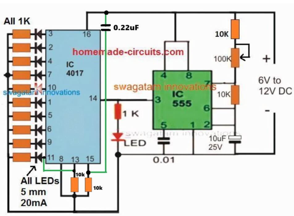
Though the more complex lighting might need the incorporation of microcontroller ICs, simpler yet very interesting light effects can be generated through ordinary ICs like IC 4017 and IC 555 as shown below.
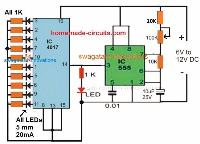
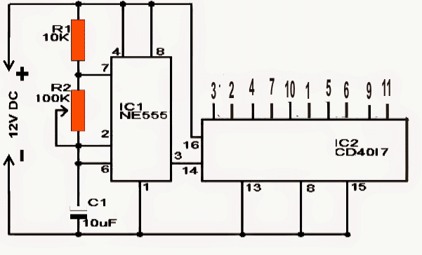
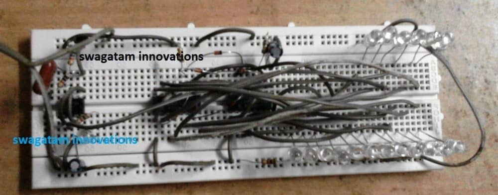
This is our first LED chaser design which requires very few components for the configuration.
(The 100K pot can be adjusted to get any desired chasing speed or rate)
Parts List
All resistors are 1/4 watt 5% unless specified
- 1K = 11nos
- 10K = 2nos
- 100K pot = 1no
Capacitors
- 0.01uF ceramic disc
- 10uF/25V electrolytic
- Semiconductors
- LEDs RED, 5mm High Bright or as desired = 11nos
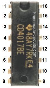
- IC 4017 = 1no
- IC 555 = 1no
- For learning the pinouts and datasheet of the IC 4017 please refer to this article
- For a detailed explanation regarding IC 555 astable, you can click on this article
As can be seen in this configuration, in response to the pulses from IC 555, the IC 4017 generates a running or chasing light pattern across the connected 10 output LEDs. The chasing pattern goes on repeating itself from start to finish as long as the IC 555 keeps pulsing pin #14 of the IC 4017.
Although the above design looks great, it is possible to create even more complex and interesting light effects using the same IC 4017 and IC 555 combination, through some minor modifications, as described below:

2) LED Knight Rider Chaser Circuit
The second concept presented below is basically a running light effect generator circuit, quite resembling the effect produced over the popular "knight rider" car.
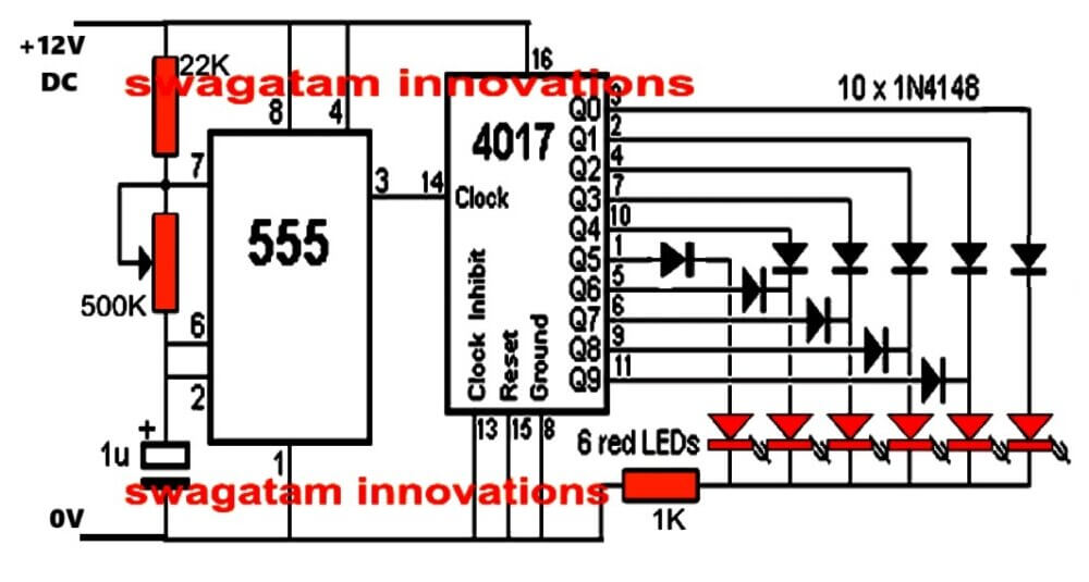
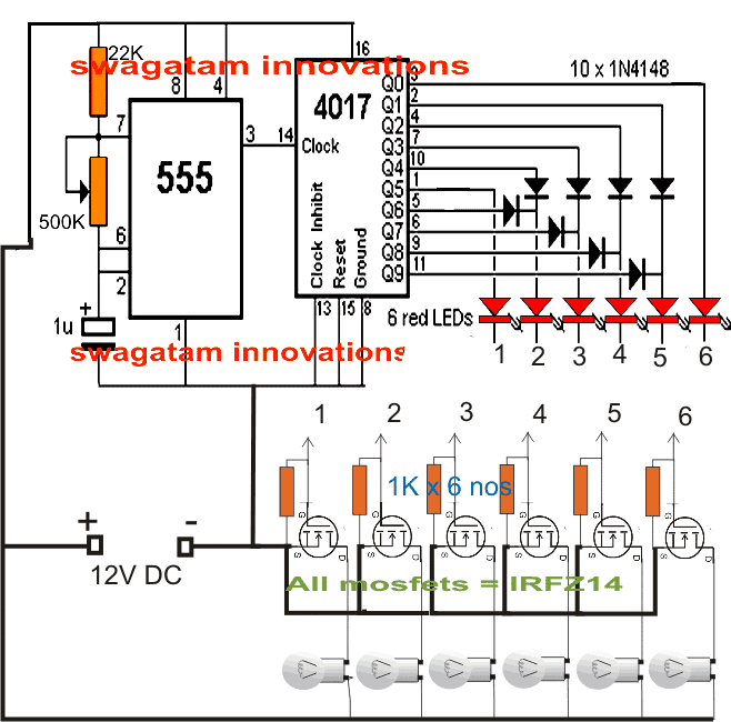
The circuit mainly comprises of IC 555 and the IC 4017 for implementing the required functions. The IC 555 is used to generate the clock pulses which is fed to the clock input of the IC 4017.
These clock pulses received from the IC555 is translated into a sequencing or chasing effect over the LEDs connected across the various outputs of the IC 4017.
In its normal mode the IC 4017 would have generated a simple start to end sequencing of the LEDs wherein the LEDs would have lit up and shut off one after the other in a sequencing pattern with a rate determined by the IC555 cock frequency, this would repeat continuously as long as the unit stays powered.
However in the proposed knight rider LED light chaser circuit, the output of the IC4017 is configured in a special way using a group of diodes which enable the output sequencing to produce a to and fro chasing of the connected LEDs, albiet through 6 LEDs only in contrast to 10 LEDs as in the normal mode.
How it Works
As can be seen in the first circuit diagram, the design produces a reverse forward moving effect of the LEDs in response to the clocks generated by the IC555 which is basically wired as an astable.
The frequency of this astable can be varied by adjusting the associated 500k pot which in turn influences the LED sequencing speed.
The entire circuit is powered via a compact transformerless power supply circuit thus avoiding the need of bulky transformers or costly SMPS.
Using Triacs and 220V Bulbs
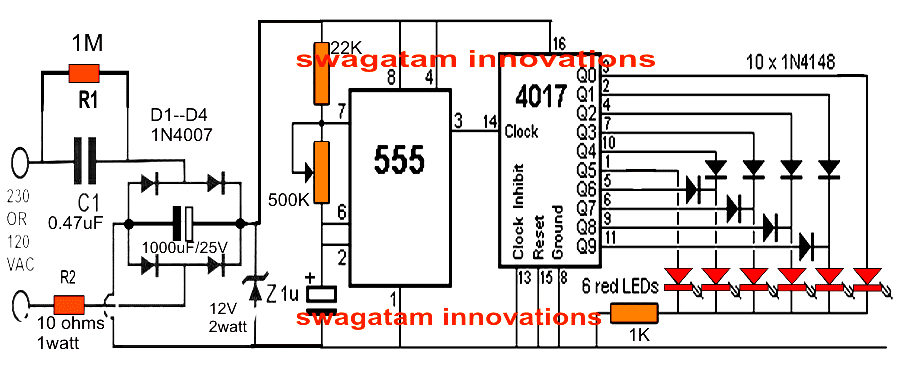
This circuit can be also modified for illuminating mains operated bulbs by incorporating a few triacs in conjunction with the LEDs present at the outputs.
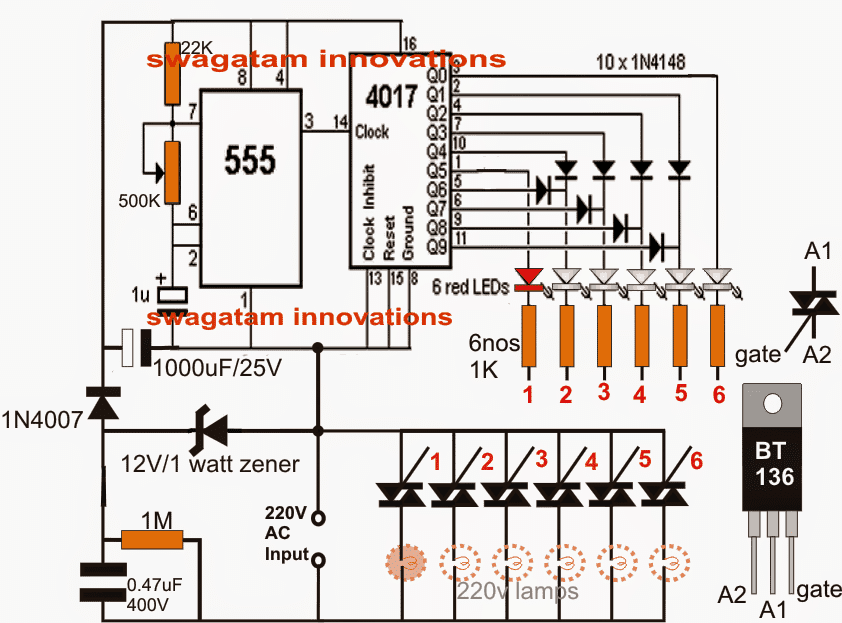
The second figure shows the complete arrangement where we can see 6 triacs being rigged across the output LED ends via 1 K resistors.
Again, this mains operated knight rider light chaser does not depend on bulky power supply stages rather employs a simple capacitive power supply for implementing the proposed running light or chasing LeD effect.
WARNING: THE CIRCUIT IS NOT ISOLATED FROM MAINS AC SUPPLY, THEREFORE IS EXTREMELY DANGEROUS TO TOUCH IN POWERED AND UNCOVERED CONDITION.
Parts List
- 1K = 1
- 22K = 1
- 1M = 1
- 10 ohms = 1
- 500K pot = 1
- 1uF/25V = 1
- 1000uF/25V = 1
- 0.47uF/400V PPC = 1
- 12V zener 1 watt = 1
- 1N4007 diodes = 4
- 1N4148 diode = 10
- LEDs = 6
- IC 4017 = 1
- IC 555 = 1
Video Clip:
Knight Rider Chaser using 12V Bulbs
The above circuit can be also as effectively used for car installation by doing the following modifications to the above circuit. The circuit shows how the design can be used for illuminating 12V car automotive lamps.
How to Calculate the 4017 LED Chaser Speed
The chaser speed can be easily adjusted by determining the correct frequency rate of the IC 555, as I have explained below:
Formula for IC 555 frequency is = 1/T = 1.44 / (R1 + R2 x 2) x C, where R1 is the resistor between pin#7 and the positive line, R2 is the resistor between pin#7 and pin#6/2. C is the capacitor between pin#6/2 and ground, and should be in Farads.
- TL = 0.693 x R2 x C (TL refers to time LOW or the OFF time of the frequency)
- TH = 0.693 x (R1 + R2) x C (TH refers to time HIGH or the ON time of the frequency)
- D = Duty Cycle= (R1 + R2) / (R1 + 2R2)
- Or,
- R1 = 1.44 x (2 x D-1) / (F x C)
- R2 = 1.44 x (1 - D) / (F x C)
The lights connected are mostly LEDs, however it can be modified for using with mains operated lamps also.
3) Simple LED Chaser using IC 74C164
Referring to our third chaser circuit diagram below, we can see a low-frequency, astable oscillator circuit, made up of two gates, IC1a and IC1b, from the IC 4011 quad two-input NAND gate.
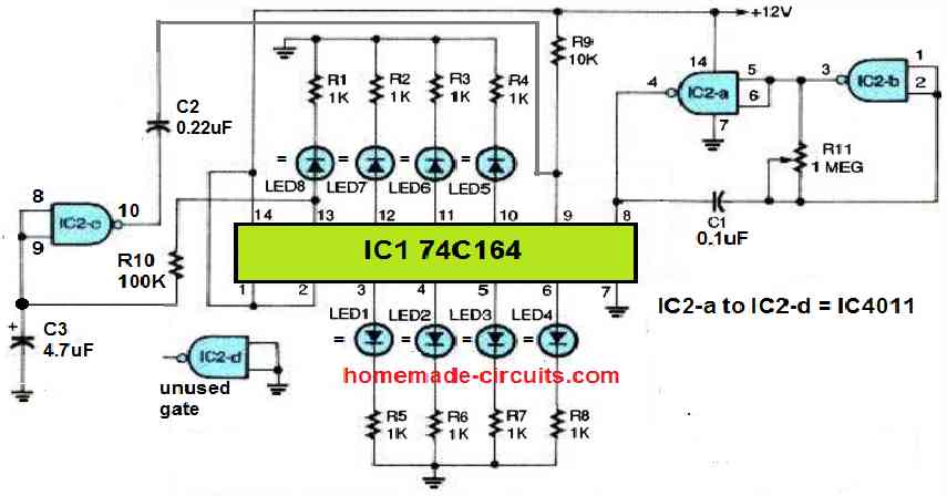
The operating frequency of this astable is determined by the values of C1 and R11. This circuit configuration works well as a clock-pulse generator for feeding the IC1's 74C164 shift register. The positive output pulses from the clock at pin 4 of IC2 are supplied into the shift register's clock input at pin 8 of IC1.
Each output of the shift register is wired to an LED. Each LED is connected to a 1K current-limiting resistor in series.
The input of gate IC2c is connected to the eighth output of the shift register, located at pin 13, via a time-delay RC configuration comprised of R10 and C3.
The output of the gate is connected to the clear input of the shift register at pin 9 through a capacitor. LED8 is turned on by the eighth clock pulse, and C3 is charged as soon as pin 13 of IC1 becomes positive.
After a little delay, the output of IC2c becomes low, clearing the outputs of the shift register.
The LEDs light up in the following sequence: LED1 is turned on by the first clock pulse, LED2 by the second, and so forth until all eight LEDs are illuminated.
The clear pulse from IC2c shuts off each LED once the eighth LED illuminates, and the process is then repeated.
R10 and C3's values can be changed to make LED8 stay on for the identical amount of time as the remaining LEDs.
For a quicker sequence, the RC time delay circuit must be smaller; and for a slower series, it must be larger. Increasing the value of R10 or C3 will shorten the delay period, and decreasing the value will extend the delay time.
4) LED Scanner Circuit Mustang Type
In next idea which is the 4rth one is also a chaser circuit which produces a LED scanner type illusion through the various sequencing illumination modes over the attached LED arrays. The idea was requested by Mr. Danely Sooknanan.
Technical Specifications
I want to build the new Knight rider mustang light for my car scoop.What i have read is. It's made up out of 480 distinct LEDs, arranged in three rows of 80 in each row, then divided up into two sides.
My question is how you build it. The size i want to work with is 12 inches in length by 1/2 inch in width. How many rows of leds will i get by that dimension. What kind of led to use? What can i use for the diffuser case? What to use for the control box.
The Design
In the actual knight rider LED scanner unit as shown in the video, there are as many as 29 number of functions to be precise, implementing those is virtually impossible using discrete components and without employing MCUs, however here we'll see how a few of these could be possibly made using just a handful of components.
The main two functions of the proposed Mustang LED scanner circuit may be assessed as given in the following description:
1) LEDs light up in a bar mode fashion from the two ends of the strip and meet up at the center, illuminating the whole module brightly.
In the next sequence the LEDs begin shutting off in the same sequence as above from the outer extreme ends until all the LEDs are switched OFF.
The rate or the speed of the above procedures are adjustable through a pot as per individual preferences.
2) The second scanning sequence is similar to the above, except the shutting off procedure which is done for all the LEDs at once instead of one at a time.
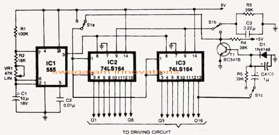
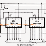
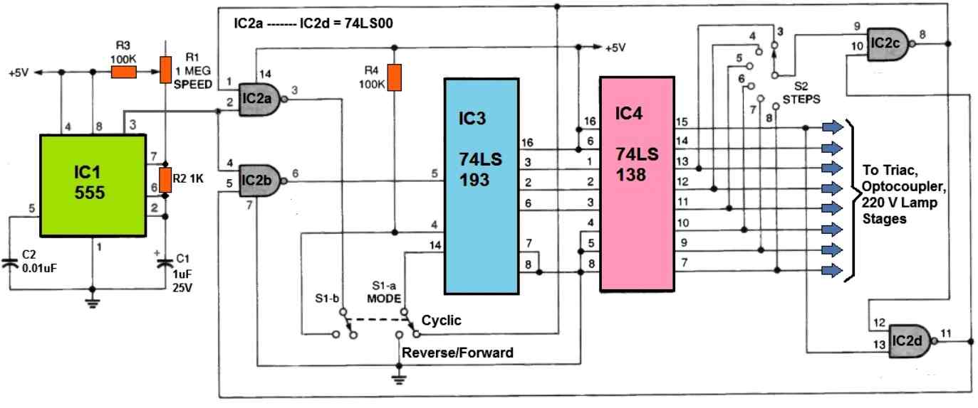
The above two functions can be easily implemented using a couple of 74LS164 ICs and a 555 IC oscillator as shown in the following circuit diagram:
Circuit Diagram
Looking for a Meteor Shower LED Effect Circuit? Please check out this article
Using IC 74LS164 as the Controller
In the shown mustang scanner LED light circuit, a couple of 8-bit parallel-out shift register ICs 74LS164 are employed, driven by the IC555 configured as the clock oscillator.
The circuit may be understood by considering the following two modes in the design:
As may be seen in the above circuit diagram, a 3 pole, 9 throw switch is used as the changeover switch for imitating the 2 functions explained in the previous section above.
In mode1 S1 is connected as shown in the circuit diagram, in this position the LEDs illuminate in an sequencing LED bar like fashion with every rising edge of the clocks from the IC555 until all the LED light up and the final "high" reaches pin16, when T1 momentarily resets both the ICs producing in instant shutting off of all the LEDs at once.
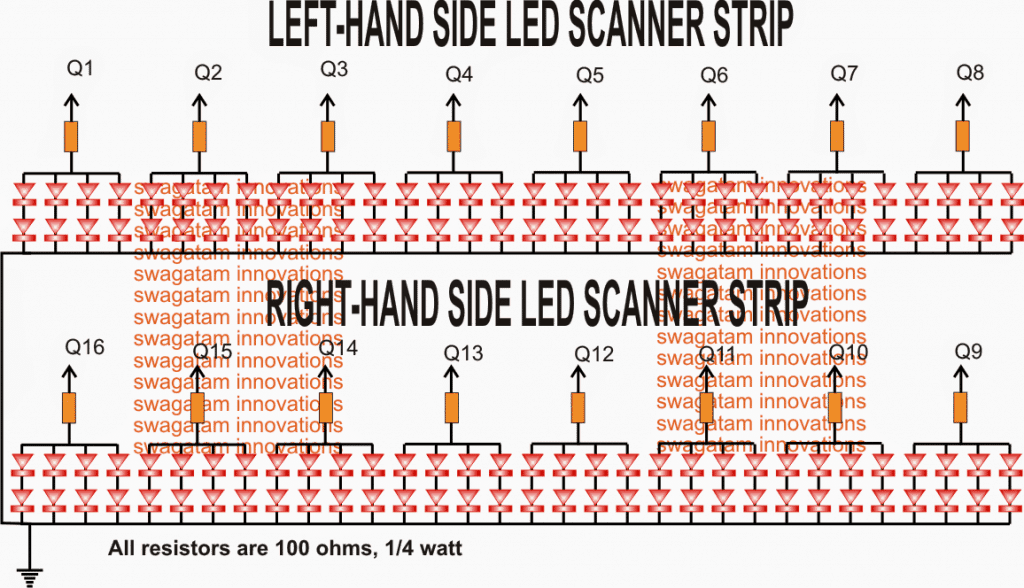
In the actual prototype the LEDs from Q9----Q16 must be arranged such that Q16 faces Q8, while Q9 faces the outer end of the relevant strip.
As soon as the above happens, a new cycle initiates afresh and the cycle repeats for so long as the S1 position isn't changed.
Mode#2
In mode 2 let's consider the switch S1 connected with the positive supply, thus S1a gets connected with the +5V line, S1b gets hooked up with the collector of T1 while S1c with R5. Also the reset pin 9 of IC1 and IC2 get connected with the collector of T1 whose base can be seen configured with the last output Q16 of IC2.
On power switch ON, the LEDs begin illuminating in a BAR like mode as before from Q1 to Q8 and from Q9 towards Q16 in response to each clock pulses supplied by the astable IC 555 at pin8 of the two 74LS164 ICs.
Now as soon as the high across the shifting outputs reach pin 16, T1 instantly inverts and renders a low to the serial pins 1, 2 of the ICs so that now the LEDs begin shutting off one by one across the arrays in the same sequence as it illuminated in response to every clock from IC 555.
The LED Sequence Keeps Recycling
The procedure keeps repeating as long the switch S1 position is not changed from its existing position.
The above two functions are pretty easily implemented and we have our LEDs scan the whole array quite in the manner the actual Mustang scanner is supposed to do.
However with the above two functions the features look much limited and we would want to insert a few more of the features as may be witnessed in the original video.
I'll keep the article updated with the new added features, but in the meantime I have explained how the LEDs could configured to the above scanner design as per the request made by Mr. Dannel. For ease of calculation and configuration we incorporate 32 + 32 LEDs on each left and right strips.
The arrangement and the connection details may be verified through the following diagram:
Enabling Rapid Up/Down Sequence
Another interesting scanner function that could be easily added to the above circuit with a feature producing rapid to and fro sequencing over the two strips in groups of four.
This could be easily done by toggling an arrangement wherein T1 would freeze once all the LEDs switch ON in bar like style.
Now in this position a 4017 with its own oscillator would come into the scene with its outputs switching OFF the lit LEDs rapidly in a reverse forward manner. The switching could be done using BJTs which would ground the relevant anodes of the LEDs in the process.
So now we have three interesting scanning sequences toggled in our very own homemade mustang LED scanner circuit, any more possible solutions are welcome from the readers.
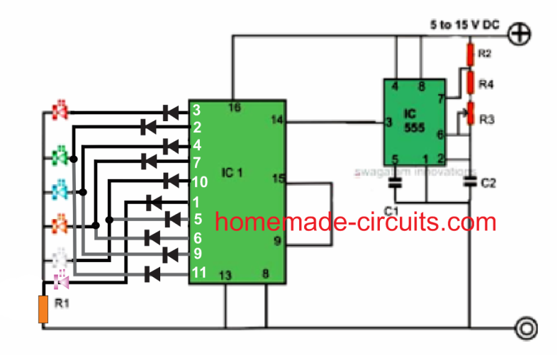
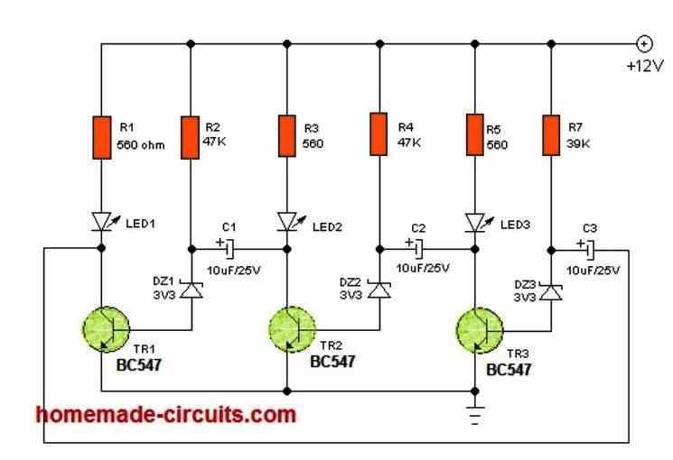
5) LED Chaser Circuit with Slow Adjustable Fading Effect
The 5th circuit below discusses a cool chasing LED light circuit that features a timed delay fading slow transition effect across the whole illuminated sequencing LEDs. The idea was requested by Mr. Tamam
Technical Specifications
I want to design a circuit consisting equal no. of Red, Green, Blue, Yellow, Violet, Orange and White LEDs. I want to have these LEDs in a continuous and smooth transition effect like
below,
At first, Red branch of LEDs lit for a preset time then slowly fade out and then Green branch of LEDs fade in and fade out then next branch fade in and so on.
I would like to have control on transition time delay, light timing, fade in or out timing if possible. And I don't want to use any Programmable IC for this. So please please let me know if it possible without any programmable IC. It is okay even if I need several ICs to accomplish the job. You just show me the way !!
Thank you very much once again for your valuable time and for a quick reply! I am looking forward to you response!!
Circuit Diagram
The Design
The proposed chasing, fading LEd light circuit may be understood with the help of the above schematic and the following description:
The upper circuit is a standard LED chaser design comprising of a decade counter IC 4017 and a clock oscillator using IC 555 astable configuration.
This IC 4017 generates a sequencing high logic (equal to supply voltage) across its entire output pins in response to the clocks at its pin14 from the IC 555.
If we connect LED directly across the 4017 outputs and ground, the LEDs would illuminate in a dot mode fashion from the first pinout upto the last in a sequencing pattern resembling a chasing effect.
This effect is pretty ordinary and we all probably have come across and built such light chasers circuits quite often.
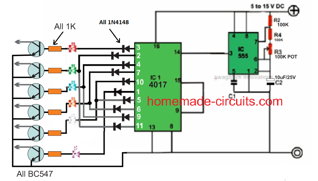
However as per the request the effect needs to be enhanced by adding a slow transition over the LED illumination as it sequences across the entire channel.
This fading transition on the sequencing LEds is expected to generate an interesting group LED chasing effect instead of an illuminated dot like appearance.
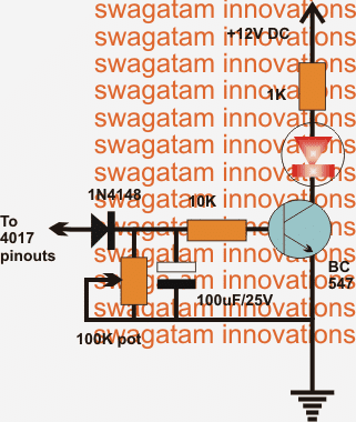
The above intriguing show could be easily implemented by connecting the LEDs to an intermediate BJT delay generator circuit.
This BJT circuit becomes responsible of generating the intended transition delay over the LED illumination and can be witnessed in the lower design.
This stage needs to be repeated across all the selected outputs of the 4017 outputs for achieving the desired chasing, fading slow transition over the LEDs.
As requested the rate of the above fading slow transition could be controlled by adjusting the given pot.
The circuit is basically a simple delay timer which sustains the illumination on the sequencing LEDs for a few moments depending upon the set value of the pot.
The stored charge on the capacitor produces this timed delay effect on the LEDs which could be predetermined as per ones own choice.
The speed of the sequencing could be also altered by tweaking the 555 IC 100k pot as per individual choice which this could in turn interfere with the delay transition effect and thus is a matter of some trial and error until the most attractive set up is determined.
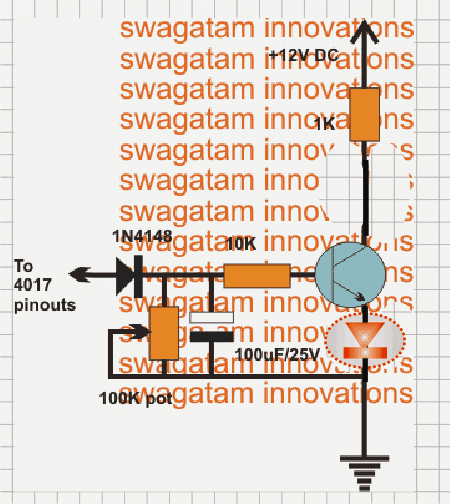
For Improved Fading effect
For an improved fading response the LED could be connected across the emitter and ground of the circuit, as indicated the below given diagram:
6) 18 LED Light Chaser Circuit Using Two IC 4017
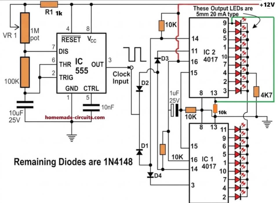
The next 6th design explains how to build an 18 LED chaser circuit through a simple cascading of two 4017 ICs, and some passive electronic components.
Working Explanation
Here we are discussing how to make a simple LED running light which can be built by any newcomer in the field albeit the individual has some knowledge of soldering and regarding the commonly used electronic components.
The concept of a light chaser discussed here utilizes the popular Johnson’s decade counter IC 4017 for getting the desired light chasing effect. IC 555 is used as the Oscillator
The IC 555 provides the clock signals to the counter ICs. We all have probably seen how the IC 4017 can be configured for creating the light chasing effect using LEDs, however the number of maximum LEDs supported by this IC is not more than ten.
In the following paragraphs we’ll learn how to make an eighteen LED light chaser by cascading two of these ICs.
Cascading two IC 4017 Johnsons Counter for the 18 LED Effect
Looking at the above light chaser circuit diagram we see how the two ICs are configured so that the “chasing” or "running"of the LEDs at its outputs are carried on for 18 LEDs.
The diodes included in the circuit especially are responsible for switching the ICs into a cascading action.
The diodes make sure the IC outputs are carried forward from one IC to another, so that the “chasing” effect is pulled for the entire 18 LEDs in the array.
The whole circuit can be built over a general purpose PCB, and connected together by soldering with the help of the shown diagram.
The circuit can be operated in between 6 volts to 12 volts.
HAVE FURTHER DOUBTS? PLEASE FEEL FREE TO COMMENT!
The above 18 LED cascaded chaser circuit can be also conveniently built using a 555 astable circuit, as shown below:
Video Clip of the above circuit in operational mode:
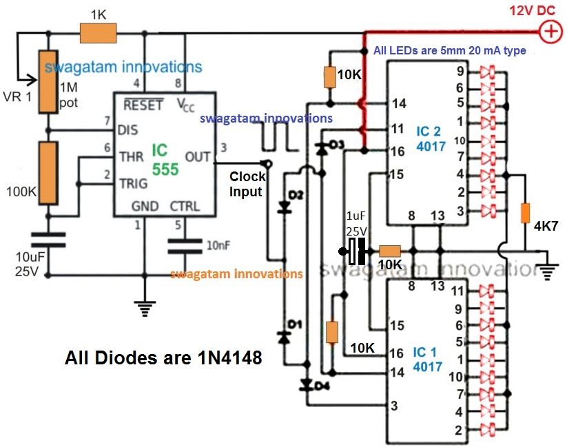
7) 100 to 200 LED Reverse Forward Chaser Circuit for Diwali, Christmas Decorations
The 7th concept below explains how to build a simple LED chaser circuit with a push pull or reverse forward sequencing effect. Also, in the later part of the article I have explained how this simple LED chaser could be upgraded to a 100 to 200 LED laser circuit with a reverse forward LED sequencing effect.
Introduction
As learned earlier, an LED light chaser circuit typically refers to an electronic configuration able to generate or illuminate a group of LEDs in some predetermined sequence. One popular IC 4017 is very commonly employed for making this type LED sequencer circuit.
Here also the IC basically is a Johnson's 10 stage decade counter/divider and can be used for many interesting light pattern generations, and may be used for various decorative purposes.
So far we have circuits using the above IC for producing chasing light effects, however making the IC create "reverse" "forward" "chasing" pattern with LEDs is something many of us might not be acquainted with. Here I have explained how to make a simple yet effective to and fro or reverse forward light chaser circuit using LEDs.
Understanding IC 4017 pinouts
But before that let's take a brief look at the IC 4017 pin out details.
The IC 4017 is a 16 pin dual in line (DIN) IC.
The IC has 10 outputs which generate the sequencing high outputs in the order of the pin outs - 3, 2, 4,7, 10, 1,5, 6, 9, 11. The sequencing takes place in response to a frequency applied at pin 14 of the iC
Pin 16 is the positive supply input, pin 8 is the negative supply input or the ground line.
Pin 13 is used clock inhibit inhibit and will stall the circuit if connected to positive supply terminal, however connecting it to ground makes everything normal, so we connect it to ground.
Pin 12 is the clock carry out, not required for single 4017a applications, so we leave it open.
Pin 15 is the reset pin, and it resets the output to the start pin in response to a positive response to it.
The pin 15 of the IC is connected to the second last pin 9 of the IC, which means the output resets every-time the sequencing reaches pin 9m,and the moment this pin goes high, the IC repeats the action by resetting the system.
Pin 14 is the clock input and requires to be fed with a square wave frequency, easy obtainable through any astable oscillator made from ICs like IC 555, IC 4049, transistors etc.
Circuit Diagram
How it Works
Looking at the shown reverse forward LED light chaser circuit, we see that basically the IC is arranged in its normal sequencing or chasing mode, however the clever introduction of the diodes at the outputs of the IC make the sequencing appear to be reversing and forwarding from start to finish and vice versa.
The smart arrangement of the diodes enables the output sequence of the IC to feed the LEDs in a way that the relevant LeDs are able to imitate a to and fro chasing pattern.
This is achieved by by forcing 5 outputs to move in a forward chasing pattern, while the following 5 outputs are redirected toward the same LEDs but in the opposite direction, making the pattern look like a to and fro chasing motion.
Parts List for the proposed 4017 LED light chaser circuit
- R1 = 1K,
- R2 = 4K7,
- R3 = 1K,
- R4 = 100K pot, linear,
- C1 = 10nF,
- C2 = 4.7 uF/25V,
- IC1 = 4017,
- IC2 = 555
Adding More LEDs
In the above example we have seen how a reverse forward LED sequencing may ge implemented over 5 LEDs, however in order to get a more interesting effect we would want to increase the number of LED to higher numbers so that the illumination increases and the visual effect is able to get much enhanced.
The following section have explained how this may be accomplished using 200 LEDs, however any number of LED could be used just by modifying the transistors and the series parallel connections for the LEDs, I have explained the details.
Circuit Operation
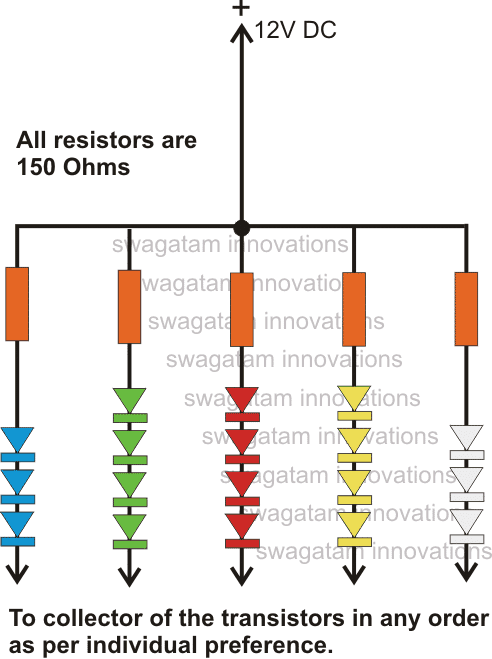
The circuit diagram shows a simple yet an effective configuration which is able handle up to 200 different colored LEDs and create the required to and fro chasing show.
The IC 4017 is the main part of the entire system whose outputs have been very cleverly manipulated using diodes.
Normally, in response to a clock signal the outputs of a 4017 IC would begin shifting sequentially from pin#3 to pin#11 covering ten of its pin outs in a certain random order.
If the LEDs are arranged in these ten outputs, one would acquire ordinary one direction sequencing of the LEDs.
In the discussed circuit, five of the end sequence pin outs have been diverted in such way that the connected LEDs produce a to and fro moving effect, however with this arrangement the total number of outputs get restricted to only 5, nevertheless sufficient for implementing the intriguing visuals.
Normally the outputs would accommodate a maximum of 4 LEDs, a total of 20 numbers. For handling as high 200 LEDs, transistor buffer stages have been included in the circuity.
Each transistor or the channel can hold upto 50 LEDs, the LEDs are connected in series and parallel combination as shown in the last diagram.
The LEDs are connected to the collector of the respective transistors as referred to in the last diagram.
The IC 555 is wired up as an astable for generating the required clock pulses at the input pin#14 of IC 4017.
These clocks determines the sequencing rate of the connected LEDs which may varied by adjusting variable resistor R3.
The circuit may be powered from a 12V battery or a 12V/3amp SMPS adapter unit.
Circuit Diagram with 200 LED Chaser Circuit
The basic reverse forward LED circuit using single LEDs can be studied elaborately in this LED scanner article, and the video can be witnessed below:
How to Connect the LEDs
The following diagram illustrates the connection arrangement of the LEDs to the above circuit. A single series for each channel has been shown in the diagram.
The numbers can be simply increased just by inserting more such series in parallel to the respective strings of the different channels.
Circuit Diagram for Series Parallel LED Connections
Parts List
- R1 = 1K,
- R2 = 4K7,
- R3 = 1K,
- R4 = 100K pot, linear,
- C1 = 10nF,
- C2 = 4.7 uF/25V,
- IC1 = 4017,
- IC2 = 555
- All diodes are = 1N4007
- All transistors are = BD139
- All transistor base resistors are = 1K
- LED resistors are = 150 Ohms 1/4 watt.
8) LED Chaser Circuit with Blinker Using IC 4017
The 8th concept presented below is also another LED chaser circuit but includes a blinking effect to the design. The circuit was requested by Mr.Joe, one of the keen followers of this blog.
The circuit initially was intended to be used for generating LED strobe light effects and was asked to be modified such that it could be used as an LED sequencer as well as a blinker. The change over would be implemented via a toggle switch.
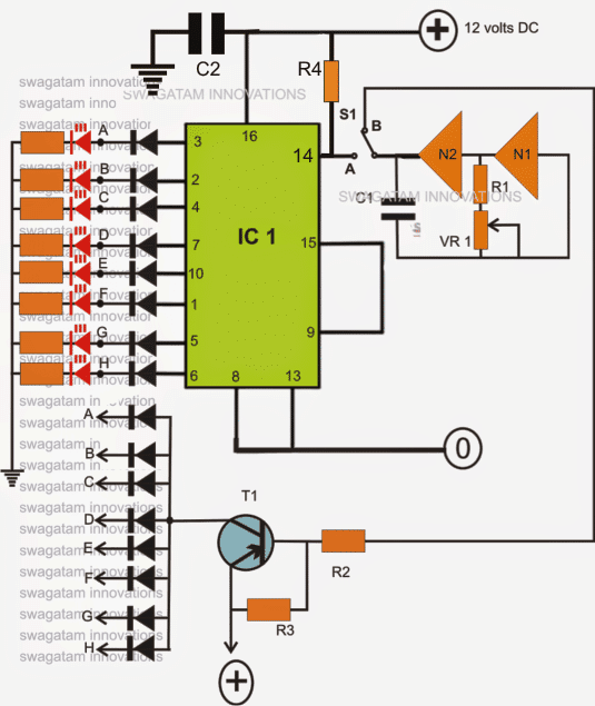
Circuit Operation
The IC 4017 is not new to us and we all know how versatile and competent this device is. Basically the IC a Johnson’s decade counter/divide by 10 IC, fundamentally used in applications where sequencing positive output signals are required or desired.
The sequencing or the orderly shifting of the outputs take place in response to a clock pulse that needs to be applied at the clock input pin #14 of the IC.
With every rising positive edge of the clock input, the IC responds and pushes its output’s positive from the existing pin out to the next pin out in the order.
Here a couple of NOT gates are used as a oscillator for providing the above clock pulses to the IC 4017. VR1 may be adjusted for determining or fixing the speed of the sequencing.
The outputs of the IC are connected to an array of LEDs in a specific order which makes the LEDs look like as if they are running or chasing during the operations.
If the circuit would be required only to produce the chasing effect, the diodes would not be required, however as per the present ask the diodes become important and allows the circuit to be used as a blinker also, depending upon the position of the switch S1.
When the switch S1 is positioned at A, the circuit behaves like a light chaser and produces the normal chasing effect over the LEDs which start illuminating in sequence from top to the bottom, repeating the operations as long as the circuit remains powered.
As soon as S1 is flicked toward B, the clock signals from the oscillator are shifted into the input of the transistor T1, which instantly stats to pulsate all the LEDs together in response to the received clocks from N1/N2 configuration.
Thus as per the requirement we have successfully modified an ordinary light chaser circuit with an additional feature through which the circuit now is also able to function as a LED flasher.
Do not forget to connect the inputs of the remaining unused gates from the IC 4049 either to the positive or the negative of the supply.
The supply pins of the IC 4049 also need to be connected to the relevant supply rails of the circuit, kindly refer to the datasheet of the IC.
If all the ten outputs of the IC 4017 are required to be integrated with LED sequencing, just connect pin #15 of the IC to ground and use the left over outputs of the IC for the required sequencing of the LEDs in the order of: 3,2,4,7,10,1,5,6,9,11
Circuit Diagram
The following parts will be needed for making this LED light chaser with simultaneous flasher circuit:
- R1, R2, R3 = 1K,
- R4 = 100k
- VR1 = 100K linear pot.
- All LED resistors are = 470 Ohms,
- All diodes are = 1N4148,
- All LEDs = RED, 5mm or as per choice,
- T1 = 2N2907, or 8550 or 187,
- C1 = 10uF/25V
- C2 = 0.1uF,
- IC1 = 4017,
- N1, N2 = IC4049
Conclusion
Guys, so these were 6 best looking LED chaser circuits for you all that could be built and applied as a decorative piece of lighting with a dazzling eye catching effect.
You can use them anywhere you like, in your home, in your vehicles, garden, hall room, for parties, on caps/hats, apparels, during festivals etc.
Think have more such ideas, please share them here for the pleasure of the entire homemade circuit community.
9) Outward Chasing LED Circuit
If you wish to make a sequencing LED pattern which will imitate LED chasing from center to outward, then you can try the following design, which is our 9th design:

Here, group of 5 LEDs will appear running from pin#3 towards pin#10, giving an impression that the LEDs are chasing from center pin#3 to pin#10, outwards on either directions.
You can replicate the effect using all the 10 outputs of the IC 4017.
10) 16 LED Reverse/Forward Chaser Circuit
In the following 10th LED chaser circuit concept, the circuit sequentially turns on and off 16 LEDs using a 24 pin decoder IC.
A four-bit binary input is used by the CMOS 4514 binary-to-decimal decoder, IC3, to go forward and activate each of the 16 outputs.
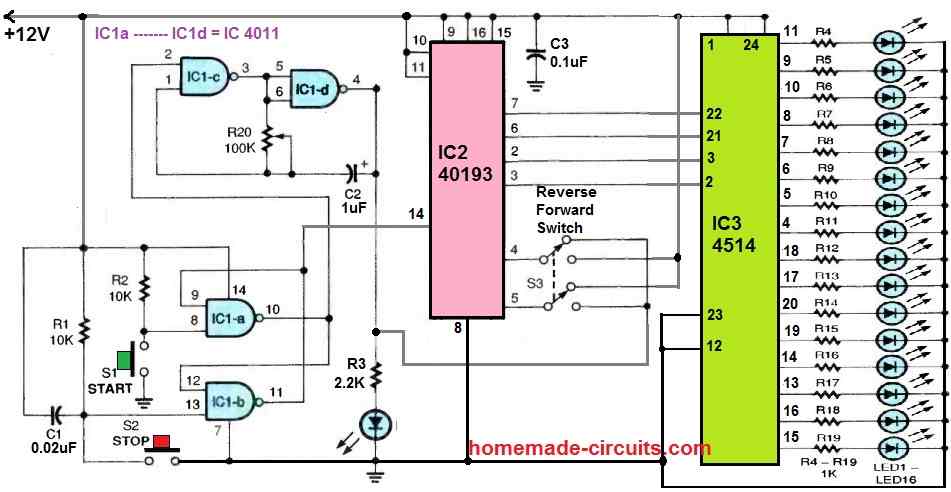
The binary input data for the 4514 decoder IC3 is provided by IC2 40193, which is a binary up/down (reverse/forward) counter.
Two gates of a 4011 quad 2-input NAND gate, IC1c and IC1d, are coupled to form a low-frequency, astable-oscillator clock circuit. C2 and R20 control its operating frequency.
IC1-a and IC1-b, the final two gates of the 4011, are set up as a set-reset flip-flop latching circuit.
Switches S1 and S2 control the start and stop functions of the device, respectively, while S3 enables the up/down sequencing feature of IC2.
This is how the circuit operates:
The oscillator is started by making pin 2 of IC1c high when S1 is pressed. This latches the output of IC1a at pin 10 high.
At the same time, pin 14 of IC2's reset input is latched low, enabling the IC to count up or down depending on how S3 is positioned.
As the clock runs, the LEDs (LED1 ot LED16) turn on and off sequentially, one at a time.
The sequence restarts once the final LED in the series turns on and off, and this sequencing keeps going until the stop switch is pressed.


Questions & Answers
sir,do u have single time LED Chaser after stop.and glow single LED >?
Bhavin, I could not understand your requirement….please explain it elaborately…
sir,need circuit diagram one time LED chasing after stop chasing
Bhavin, if you want the LEDs to illuminate sequentially only once, and then stop with one LED lit up, you can try the following circuit, see how pin#13 and pin#15 are configured:
in this diagram last 11 no pin glow and 14 no pin blinking
Yes, that will happen, because one full chasing sequencing stops at the last pin11, as you wanted. You can remove pin14 LED, if you don’t want it…
I want to make a round LED chaser circuit. It will be placed around the doorbell switch
You can remove LEDs on pin11 and pin14, if you do not want them…
no of led increase 18 then what will circuit diagram
use the 74LS164 based circuit.in this solution how many led operate in single ic
8 LEDs on one IC:
https://www.homemade-circuits.com/led-chaser-circuit-using-ic-74ls164-leds-illuminate-in-bar-mode-then-shut-off-together-or-one-by-one/
please share circuit diagram
It is given under 4) LED Scanner Circuit Mustang Type, in the above article…
sir,planning change in circuit.LED chase once after all LED are glow.please share circuit diagram
4017 circuit cannot easily modified for LEDs to glow all together after one chase, for that you may have to use the 74LS164 based circuit explained in the above article…
You can try this:
love your 18 chaser light circuit only problem it needs to run on 1.2v dc i want
to use on my solar light i have in my yard that failed. it is a 8 pin single ic that
runs all 18 leds. so your circuit peaked my interest. the original 8 pin ic i cant
see any numbers on it to maybe replace it. so im looking at your circuit with
the 555 and a pair of 4017. any thoughts on what to do?
gary
I am glad you found the circuit interesting, however the IC 4017 and 555 cannot work with voltages below 3V, so 1.2V seems too low for them to operate correctly.

You caan do one thing, boost the 1.2V to maybe 5V and see if the 18 LED circuit works or not.
For the 555 IC please replace it with IC 7555 or LMC555 versions.
For bosting 1.2V to 5V, you can try the following circuit:
Hi Swagatam,
First, thanks for all your efforts.
I have doubt, may be a silly one. In the 18 LED light chaser circuit, how long can I expect the circuit to function efficiently, that is without the battery getting heated or the LEDs getting burnt out. Is it safe to use the same circuit with the mentioned components as I would like to build it for a school project?
Thanks in advance.
Thanks Uma,
There’s no way the circuit can degrade or LEDs burn as long as the DC supply is as per the design specifications…It can keep on working efficiently practically forever..
Yes, it is 100% safe to use the design as exactly shown in the diagram with the indicated supply voltage DC.
You can surely build it for your school project, and let me know if you have any issues with the working of the circuit..
I was hoping to see the dual 4017 knight rider circuit in action, but the link did nothing. Do you have a video of the fading effect also?
Thanks.
which link are you referring to??
Hi
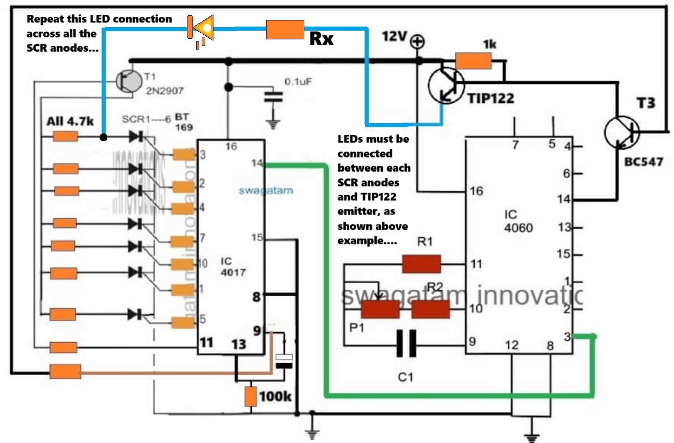
Swagatam finally got to work on the modified chaser circuit found a error on my side the leds flash now after they go through a sequence then latch then the whole array flash a couple of times but they won’t reset just stay static as if the tip122 is keeping them lit and won’t reset if I disconnect the 1uf cap at pin 9 of the 4017 the led will reset but not flash connecting this cap back the leds will flash but not reset
would you have any ideas
regards
Thank you Sparks, glad to know the LEDs are doing are sequencing and flashing as required.
It seems like the capacitor is leaking current to pin#13, that is why it is getting permanently latched.
Please replace the pin#9 capacitor with a 1uF non-polar capacitor, and the associated 100k with a 1M.
And now check the difference.
Hi swagatam
Thanks will let you know how I get on
regards
Sure Sparks, no problems!
Hi Swagatam
The lights do not flash after the last count and do not reset when I connect the supply the 4017 Counts but will not flash or reset eg LEDs will stay illuminated
regards
Thanks Sparks, please do the following modifications:
please connect pin#15 to ground through a 10k resistor, and connect a 0.1uF between the positive supply and pin#15, this will ensure the sequencing always starts from pin#3 onwards whenever the circuit is powered ON..
Use a non-polar capacitor 1uF for the pin#9 of 4017.
Disconnect the base of TIP122 from the collector of the BC547.
Now check how the LEDs respond. Tis will confirm the basic work of the circuit as per the following concept:
https://www.homemade-circuits.com/sequential-bar-graph-turn-light/
Please let me know the results…
hi Swagatam
I have already taken the bc547 emitter to pin 1 but what is strange is that it will start sequencing but for some reason will not reset and will not flash at the end of the cycle it works ok using the original circuit but I am having problems with the modified circuit to get it working as it should
reqards
Hi Sparks,
You said that the 4017 circuit stage works correctly and the LEDs illuminate sequentially and also reset normally to repeat the process when it is tested as a standalone circuit. So can you please tell me in what situation does this normal working stops, meaning with which circuit connection does this normal functioning gets disturbed and stops?
hi swagatam
thank you for your quick reply if I leave the emitter open and say connect the led to the 2n2907 collector and to to scr anode the led will be lit and reset and.start the sequence but when I connect it to the tip122 emitter the led will be lit (but not reset or flash the leds )
reqards
sparks
Hi Sparks,
please connect the emitter of the BC547 with pin#1 of IC 4060 to slow down the flashing effect.
The scrs should turn off once the 4017 sequence reaches pin#11. Because at pin#11 2N2907 turns off so there’s no holding current for the SCRs, and since the LEDs are flashing that means these would also cut off current at one instant, which would mean all SCRs latch breaking off due to the complete absence of anode/cathode current and gate current, so at this moment the SCRs would turn off.
Please let me know.
Hi swagatam
A while back you did me modified circuit of.the sequential led array light circuit (that worked ) Then you designed so all the led I am using all flashed at once then reset but I have build it and cannot get it to work you said connect load to Tip122 and anode on scr but the lights stay on plus they no ref to ground
the transistors Tip122 and 2n2907 are both at +voltage
hope you can help
reqards
hope
Hi Sparks,

Yes, I think you are referring to the following circuit idea.
We will have to check and diagnose the circuit step wise.
Initially can you please tell me how the LEDs respond without the TIP122 emitter connected (open)?
BUEN DIA Y CORDIAL SALUDO
DESOHACER UN LETRERO LUMINOSO CON MAS DE 100 LEDS Y ME GUSTARIA CONOCER ESQUEMAS QUE ME PERMITAN ESTO USANDO POCOS ELEMENTOS, TALES COMO:
LEDS
RESISTENCIAS
CAPACITORES
TRANSISTORES
OTRS ELEMENTOS QUE CONSIDEREN INDISPENSALES
Sure, you can try the following circuit design. You can put 4 LEDs in series on each transistor collector arm, adjusting the series resistor value accordingly:
Hi Swagatam, I built the outward chasing LED circuit No:9 by connecting all the parts as shown in your diagram. But my circuit is not working. Capacitor value is shown as 470uF 25V. Is it correct? Can you please assure me that there is no error in the circuit diagram?
Hi Mahesh,
There’s no error in the outward LED chaser circuit configuration, except the IC 555 part values. Please change them to the following values. Replace the 1M pot with 100k pot, 22k resistor with 100k resistor, and 470uF capacitor with a 10uF/25V capacitor. Also, please replace the 555 pin#3 1K resistor with a 10k resistor.
Goodmornig Sir. In the Knight Rider Chaser schematic it mentions 10x1n4008 diodes but only 8 of them are visible. Maybe they go on outputs d1 and 3 of the 4017?
Thanks
Good Evening Rosario,

I think the diodes needs to be configured in the following way, if 10 diodes are used:
Hi Swagatam,
In the circuit 16 LED Reverse/Forward Chaser Circuit, if I wanted to use only 14 LED, omitting the last 2, would the circuit continue to function normally?Best Regards.
Nélio.
Hi Nelio,
Yes, if you do not use the last two inputs the circuit should still work normally, according to me.
But since this circuit is not designed by me, I am not entirely sure about its functioning and whether it will successfully work or not, and also I am not well-versed with those ICs.
In your circuit No. 6 – 18 Led chaser circuit If I want to use 3 mm Led
then what changes should I Do ?
No need to change anything in the design, you can use the same circuit design without any changes….
Hi Swagatam,
I have had a look through the prior projects and experiments and could not find a suitably matched project for my needs.
I need to build a circuit that makes 3 or 4 LEDs “breathe” – fade in/ fade out over 2 to 5 seconds. There is a FADE IN/OUT Arduino project in the library but I do want to incorporate Arduino for this setup. I read about using 2 NE555s set slightly out of phase and the pulsing would be equivalent to the beat frequency of the output. The article lost me when it was suggesting XORing the output to the LEDs. Does this make sense to you? How would you do this? Or would you do it differently?
Thanks
Thank you Michael,
Did you check the following article?
https://www.homemade-circuits.com/alternate-onoff-led-fader-circuit/
I think this circuit should be able to fulfill your requirement.
A 5 seconds timer can be added through additional BJT circuit stage.
Please let me know if there’s any specific thing missing in the design.
Alternatively, a single 4093 IC could be also used to get all the required feature from a single chip.
Thanks for this. It’s virtually perfect as is. Any ideas how to make the LEDs brighter. It looks like the highest voltage through them is around 5v. Do you think I could safely bump the input to 19v? What is the BJT circuit?
Cheers
Sure, the LED brightness can be adjusted by adjusting the values of the R6 and R7 resistors.
The IC can work with up to 32 V, so 19 V can never be an issue. Just make sure the voltage rating of C1 and C2 capacitors are at least 1.5 times of 19V or higher. The R6, R7 must be appropriately calculated so that the current does not exceed their max specifications.
The transistors T1 and T2 are the BJTs, and form the BJT circuit.
Hello, Swagatam!
First, THANK YOU for having this website! It’s very generous to do this 🙂
I’m very interested in Circuit #1 and Circuit #5, because those look like something I can actually do and my goal is that I want something I can fit into a sort of “shadowbox greeting card” to be mailed to people.
My question is:
Since I’m looking at either the TLC551 or the LMC555, which as far as I can tell operate a 1V and 1.5V respectively, which values do I need to recalculate to run off of a 3V battery? Or is that not even do-able? I can go up to 6V, because I’ll be using CR2032 button cell(s) and minimal holders.
I’ve been looking, and asking, for the answer of how to go from a 5V-NE555, to a 1V or 1.5V CMOS-555 for three months – no exaggeration! -, but I still have no idea at all what values I need to recalculate to adjust the circuit from the NE555 to the CMOS low-power 555 or 551 IC.
If you could tell me what to recalculate, that would be a huge kindness! Not even do the calculations, but only tell me which things need to be recalculated, would be a big help!Even if I still need 6V but maybe only need to add a resistor to not “blow out” the CMOS timer, if you could tell me that, it would be a major kindness to me!
Thank you!
Hi Kris,
Thank you so much for liking this website, glad you found it useful.
If you check the datasheet of the cmos 555 ic it shows a formula for calculating the operating frequency which does take the supply voltage into account.
https://www.homemade-circuits.com/cmos-ic-lmc555-datasheet-works-with-1-5-v-supply/
That means regardless of the supply voltage the resistor capacitor values can remain the same.
So you can feel free to use the same circuit configuration which are shown in the above article for your specificapplication.
I think a 3V battery supply would be more appropriate instead of a 1.5V, as it would allow sufficient voltage margin for optimal illumination of the LEDs.
Please let me know if you have any further questions or doubts, I will be most happy to solve them for you.