The presented 3 phase VFD circuit (designed by me) can be used for controlling the speed of any three phase brushed AC motor or even a brushless AC motor. The idea was requested by Mr. Tom
Using the VFD
The proposed 3-phase VFD circuit can be universally applied for most 3-phase AC motors where the regulation efficiency is not too critical.
It can be specifically used for controlling squirrel cage induction motor speed with an open loop mode, and possibly also in the closed loop mode which will be discussed in the later part of the article.
Modules Required for 3 Phase Inverter
For designing the proposed 3 phase VFD or variable frequency drive circuit the following fundamental circuit stages are essentially required:
- PWM voltage controller circuit
- 3 phase high side/low side H-bridge driver circuit
- 3 Phase generator circuit
- Voltage to frequency converter circuit for generating V/Hz parameter.
I have explained the functioning details of the above stages with the help of the following explanation:
A simple PWM voltage controller circuit can be witnessed in the diagram given below:
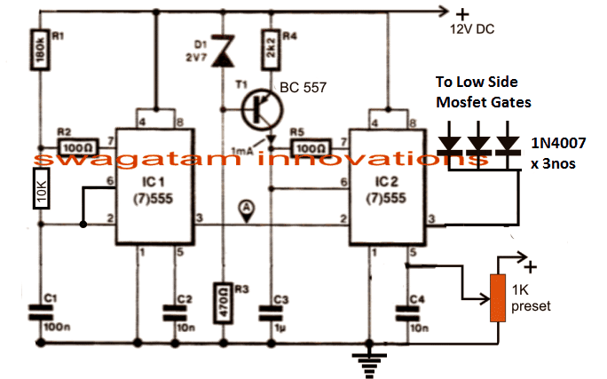
The PWM Controller
I have already incorporated and explained the functioning of the above PWM generator stage which is basically designed for generating a varying PWM output across pin3 of IC2 in response to the potential applied at pin5 of the same IC.
The 1K preset shown in the diagram is the RMS control knob, which may be appropriately adjusted for acquiring the desired proportionate amount of output voltage in the form of PWMs at pin3 of IC2 for further processing. This is set to produce a corresponding output that may be equivalent to the mains 220V or 120V AC RMS.
The H-Bridge Driver Circuit
The next diagram below shows a single chip H-bridge 3 phase driver circuit using the IC IRS2330.
The design looks straightforward as most of the complexities are handled by the chips in-built sophisticated circuitry.
A well calculated 3 phase signal is applied across the HIN1/2/3 and LIN1/2/3 inputs of the IC through a 3 phase signal generator stage.
The outputs of the IC IRS2330 can be seen integrated with 6 mosfets or IGBTs bridge network, whose drains are appropriately configured with the motor which needs to be controlled.
The low side mosfet/IGBT gates are integrated with the IC2 pin#3 of the above discussed PWM generator circuit stage for initiating the PWM injection into the bridge mosfet stage. This regulation ultimately helps the motor to gain the desired speed as per the settings (via the 1 k preset in the first diagram).
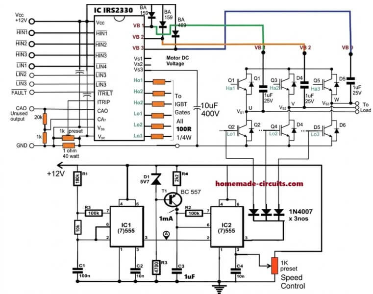
In the following diagram we visualize the required 3 phase signal generator circuit.
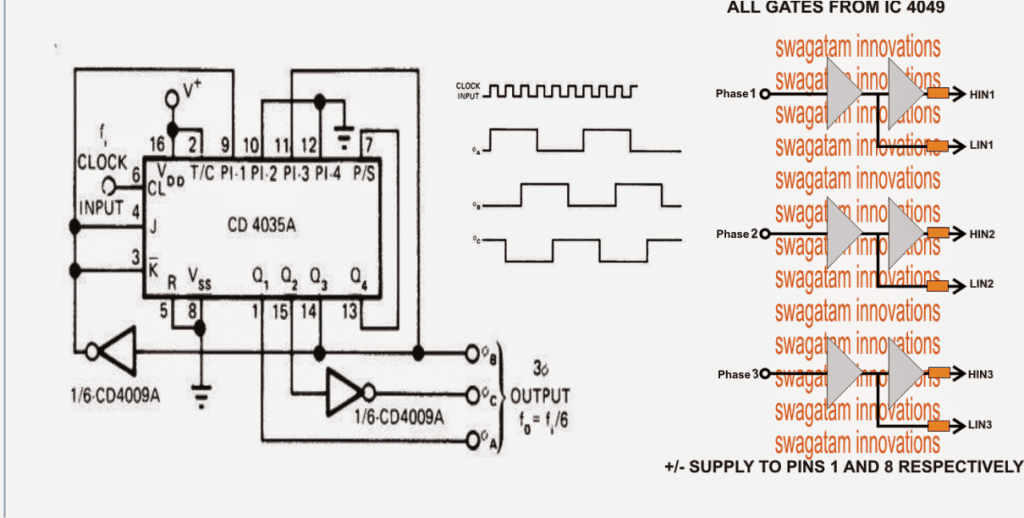
Configuring the 3-Phase Generator Circuit
The 3 phase generator is constructed around a couple of CMOS chips CD4035 and CD4009 which generates accurately dimensioned 3 phase signals across the shown pinouts.
The frequency of the 3 phase signals depends on the fed input clocks which should be 6 times the intended 3 phase signal. Meaning, if the required 3 phase frequency is 50 Hz, the input clock should be 50 x 6 = 300 Hz.
It also implies that the above clocks could be varied in order to vary the effective frequency of the driver IC which in turn would be responsible of varying the motor operational frequency.
However since the above frequency alteration needs to be automatic in response to the varying voltage, a voltage to frequency converter becomes essential. The next stage discusses a simple accurate voltage to frequency converter circuit for the required implementation.
How to Create a Constant V/F Ratio
Typically in induction motors, in order to maintain an optimal efficiency of the motor speed and toque, the slip speed or the rotor speed needs to be controlled which in turn becomes possible by maintaining a constant V/Hz ratio. Since the stator magnetic flux is always constant regardless of the input supply frequency, the rotor speed becomes easily controllable by maintaining the V/Hz ratio constant.
In an open loop mode, this can be done roughly by maintaining predetermined V/Hz ratios, and implementing it manually. For example in the first diagram this may be done by suitably adjusting the R1 and the 1K preset. R1 determines the frequency and the 1K adjusts the RMS of the output, therefore by suitably adjusting the two parameters we can enforce the required amount V/Hz manually.
However to get a relatively accurate control of an induction motor torque and speed, we have to implement a closed loop strategy, wherein the slip speed data needs to be fed to the processing circuit for an automatic adjustment of the V/Hz ratio so that this value always remains near about constant.
Implementing the Closed Loop Feedback
The first diagram on this page can be suitably modified for designing the closed loop automatic V/Hz regulation as shown below:
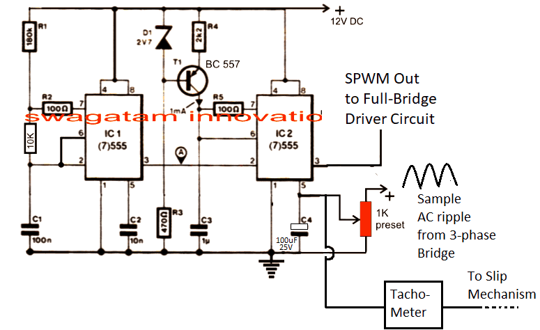
In the above figure, the potential at pin#5 of IC2 determines the width of the SPWM which is generated at pin#3 of the same IC. The SPWM are generated by comparing the mains 12V ripple sample at pin#5 with triangle wave at pin#7 of IC2, and this is fed to the low side mosfets for the motor control.
Initially this SPWM is set at some adjusted level (using 1K perset) which triggers the low side IGBT gates of the 3-phase bridge for initiating the rotor movement at the specified nominal speed level.
As soon the rotor rotor begins rotating, the attached tachometer with the rotor mechanism causes an proportional additional amount of voltage to develop at pin#5 of IC2, this proportionately causes the SPWMs to get wider causing more voltage to the stator coils of the motor. This causes further increase in the rotor speed causing more voltage at pin#5 of IC2, and this goes on until the SPWM equivalent voltage is no longer able to increase and the stator rotor synchronization attains a steady-state.
The above procedure goes on self adjusting throughout the operational periods of the motor.
How to Make and Integrate the Tachometer
A simple tachometer design can be seen in the following diagram, this could be integrated with the rotor mechanism such the rotational frequency is able to feed the base of the BC547.
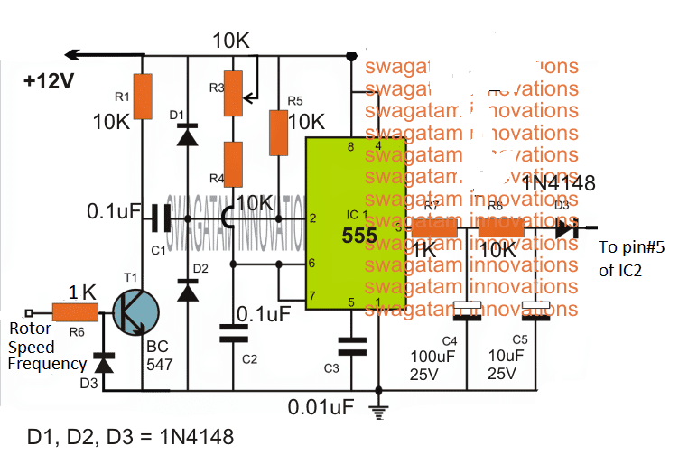
Here the rotor speed data is collected from a hall effect sensor or a IR LED/Sensor network and is fed to the base of T1.
T1 oscillates at this frequency and activates the tachometer circuit made by appropriately configuring an IC 555 monostable circuit.
The output from the above tachometer varies proportionately in response to the input frequency at the base of T1.
As the frequency rises the voltage at the extreme right side D3 output also rises and vice versa, and helps to keep the V/Hz ratio to a relatively constant level.
How to Control Speed
The speed of motor using constant V/F can be achieved by altering the frequency input at the clock input of IC 4035. This can be achieved by feeding a variable frequency from a IC 555 astable circuit or any standard astable circuit to the clock input of IC 4035.
Changing the frequency effectively changes the operating frequency of the motor which correspondingly lowers the slip speed.
This is detected by the tachometer, and the tachometer proportionately reduces the potential at pin#5 of the IC2 which in turn proportionately reduces the SPWM content on the motor, and consequently the voltage for the motor is reduced, ensuring motor speed variation with the correct required V/F ratio.
A Homemade V to F Converter
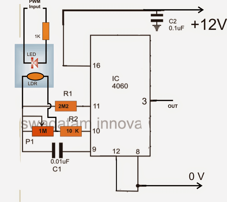
In the above voltage to frequency converter circuit a IC 4060 is used and its frequency dependent resistance is influenced through a LED/LDR assembly for the intended conversions.
The LED/LDR assembly is sealed inside a light proof box, and the LDR is positioned across a 1M frequency dependent resistor of the IC.
Since the LDR/LDR response is fairly linear, the varying illumination of the LED on the LDR generates a proportionately varying (increasing or decreasing) frequency across pin3 of the IC.
The FSD or the V/Hz range of the stage could be set by appropriately setting up the 1M resistor or even the C1 value.
The LED is voltage is derived and illuminated through the PWMs from the first PWM circuit stage. It implies that as the PWMs vary, the LED illumination will also vary which in turn would give rise to a proportionately increasing or decreasing frequency at pin3 of the IC 4060 in the above diagram.
Integrating the Converter with VFD
This varying frequency from the IC 4060 now simply needs to be integrated with the 3 phase generator IC CD4035 clock input.
The above stages form the main ingredients for making a 3 phase VFD circuit.
Now, it would be important to discuss regarding the DC BUS required for supplying the IGBT motor controllers and the setting up procedures for the entire design.
The DC BUS applied across the IGBT H-bridge rails may be obtained by rectifying the available 3 phase mains input using the following circuit configuration. The IGBT DC BUS rails are connected across the points indicated as "load"
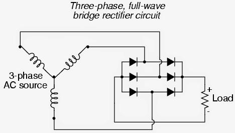
For a single phase source the rectification may be implemented using standard 4 diode bridge network configuration.
How to Set Up the proposed 3 phase VFD circuit
It may be done as per the following instructions:
After applying the DC bus voltage across the IGBTs (without the motor connected) adjust the PWM 1k preset until the voltage across the rails become equal to the intended motor voltage specs.
Next adjust the IC 4060 1M preset in order to adjust any of IC IRS2330 inputs to the required correct frequency level as per the given motor specifications.
After the above procedures are completed, the specified motor may be connected and supplied with different voltage levels, V/Hz parameter and confirmed for an automatic V/Hz operations over the connected motor.


Questions & Answers
Hello sir,
Generally, In other VDF circuits comparator is used to generate the pwm which is corresponds to given signal i.e, sine wave or square wave.In your circuit ,How did you give a separate pwm signal that is not corresponds to the input. If this pwm is not given to it what happens
Hello S.Sageyu, a synchronized PWM is good but it's not absolutely necessary, in the above circuit the PWMs are adjusted so that the output's RMS matches with the AC mains voltage RMS. This reduces harmonics and creates safe voltage parameters for the motor. if the PWM is not introduced then the output will be a square wave with a lot of harmonics and generate noise while the motor is running.
Sir, I have decided to use FGA25N120D IGBT.Is this IGBT can be used for up to what hp motor?can i use the IR 2130 instead for IRS 2330 in your circuit.
this IGBT may be capable of handling upto 50Hp motors if the voltage is 1kv, otherwise upto 10hp at 220V
yes the two ICs can be replaced with each other
Hello sir fine?i have almost finish the above circuit using the igbt Fga 25n120d.i have littlebit confused that if the additional soft recovery diode is need for this IGBT or not in case of inductive load
It is recommended to ensure 100% safety for the devices, so you should include it.
Sir,can I use the fast rectifier diode instead for soft recovery diode since it is not available in the shop.
In case it is not possible tell me the alternate solution
yes you can
Hello sir, can i use it for 5hp 3phase 415volts ac motor? is there any modification need to be run?
Hello Sivaraj, you can use any wattage motor as per your specifications just by upgrading the IGBTs appropriately
Sir, if this circuit is used for a submersible motor of 10 HP, 415V with long cable of 1000 feet , it need any choke in its output?
then , what will be the swg and turns of the choke.
Hi SS, presently I do not have its calculation details, I'll try to investigate and possibly update it for you in the above post.
Hi sir,I have refer other vfd circuits also. they said,"if the frequency of the pwm is b/w 3.5khz to15khz only, the motor will be run with less hormonics. Otherwise it will damage the bearings".
In your circuit, what will be the frequency of the pwm from 555 IC?
Hi Sageyu, here it's only 80Hz, but you may increase it to 8kHz by reducing C1 to 1nF
please explain how the voltage is changing in this ckts. and explain that with low frequency low voltage and high frequency high voltage is provide the ckt m i right?
Good day Sir,
Can you please post another circuit for a single phase brushed/brushless A/C motor. Thanks in advance.
please refer to the following post:
https://www.homemade-circuits.com/2013/09/single-phase-variable-frequency-drive.html
Hello Sir,
I am a littlebit confused about connecting the 4049 in the 3phase generator. Vcc (+) goes to 1, -/GND to 8, but I don't understand the connection between 4035 Q1/2/3, 4049 & HIN/LIN 1/2/3 of the driver. Could you pls elaborate on it a little? Thx
Hello Julio,
Q1,Q2, Q3 are associated with two more NOT gates from the IC CD4009. The 3 phase outputs from the 4035 circuit connects with the inputs of the 4049 circuit marked phase1, phase2, phase3…the outputs from the 4049 gate then integrates with the relevant pins HIN, LIN of the main driver IC.
furthermore 4035 IC will need a 555 atable multivbrator circuit for acquiring clock signals at its pin#6
Yepp, I intend to make a multiplicator using a CD4046 PLL + SN74LS92 counter. It will make a reliable and fast 6x multiplication of the modulation frequency coming from IC1 555.
Regarding the 4049, so let's say I connect 4035 Q1 to 4049 A (pin3) and LIN1 of the driver, and get HIN1 from 4049 G (pin2)? And similarly for the pins 5/4 and 6/7 for phase 2/3?
OK, that's great!
and yes your mentioned procedure is correct!
Hello Swagatam, ltns 🙂
I was just wondering the other day – why do we need a multiplicator at all? Why dont we use IC1 & IC2 to generate 6x the desired frequency from the beginning? I mean if we need 50Hz x 3phase signal, lets generate 300Hz on IC1 and call it a day. Eventually in case of PWM frequency of 10kHz let's make it 60kHz on IC2. Let's say we don't want to go under 20Hz base modulation frequency, so we use the appropriate resistor in parallel to the control pot. Also for a standard 3ph motor we don't need more than let's say 100Hz, let's limit the pot size. So all in all, the applied modulation frequency would be between 120-600Hz with PWM of 60kHz (or even 120), directly on input of the 3 phase signal generator w/o the need of 6x multiplication. What am I overlooking? Some 555 limit?
Hello Julio, sorry I could not interpret your suggestion.
where do you think the PWM could be applied directly?
By multiplicator I believe you are referring to the mosfet driver IC stage, right? Please elaborate more on this.
OK, seems like I messed up a little. Let me explain.
1. In your diagrams you use a pair of 555s as a PWM voltage controller to generate the PWM signal at the required modulation frequency (let's say modulation frequency fm = 50Hz with the pulse frequency fp = 10kHz).
2. That PWM signal goes then to the frequency converter. You used a CD4060 with a coupled LED/LDR, I decided to use a CD4046 PLL + SN74LS92 counter (doesn’t matter, does the same). On the output you get your PWM signal with 6x fm (and also 6x fp for that matter).
3. That multiplied PWM signal at 6fm and 6fp serves as a clock for the CD4035 Shift Register (3 phase signal generator stage), which divides the clock signal to 3 LIN/HIN pairs using CD4049.
Now my question/idea is the following – how about to omit the frequency converter (point 2) altogether, generate the PWM (point 1) already at 6fm and 6fp to feed it to the shift register (point 3)?
I am still confused! you mean to say you want to eliminate the IC 555 stage?
then how would you generate the PWMs corresponding to the varying 220V AC? These PWMs ultimate determine the RMS of the output voltage to the motor equivalent to the input mains AC
Nonono, I mean to eliminate the frequency converter stage. And generate the PWMs at 6x frequency from the beginning. As I said, you need a 3 phase 50Hz PWM signal on output. So you generate 6x50Hz = 300Hz from the 555s with the corresponding pulse frequency of 6x10kHz = 60kHz, and you have the same result as your original design after the frequency converter stage. Do I understand that correctly? Maybe I can't explain myself, or am I missing something?
please ignore the previous comment, may be I got it now.
you want to eliminate the frequency converter stage which uses the 4060 IC or the one that you have referred to using 4046/74LS92, right?
well this stage is employed to make the system automatic, so that the VFD becomes independent of manual adjustments, and is able to read the mains fluctuations and auto-adjust the V/F ratio for the motor.
Hmmm, now I'm confused. What mains fluctuations are you referring to? The input 1phase or 3 phase AC mains is rectified to DC both for the high voltage power stage and for low voltage 5 & 20V logic stage. The pulse frequency is constant and the pulse width only depends on the modulation frequency wave amplitude (at least after your soft start circuit saturates, thx for that one, too), which frequency depends on the settings of R1 (replaced with a pot) and C1.
I feel like we are talking about the same think but somehow struggle to understand each other. Also it seems to me I am missing something terribly. Maybe I won't find out till I build the circuit finally at least on a breadboard. I wish I could skype you.
sorry…. actually it's not about the mains fluctuation issue, the frequency converter stage is for making the unit automatically compatible with all the the viable voltage input ranges, such as 440V, 120V, 220V, etc so that it becomes universally acceptable for all, and no manual settings are required by the user who buys the unit.
sorry I do not have a skype account, but now it seems we have almost sorted it out finally
….the frequency may be constant from IC1 of the first circuit, but the PWM from IC2 is dependent on the 12V supply, which is in turn proportionately dependent on the mains input voltage level….so this PWM needs to be converted into a proportionately adjusting frequency for the driver stage and eventually for the motor….otherwise if the frequency is not changed, then the V/F ratio would become incorrect for the particular motor and the whole purpose of the circuit would become zero.
Brother i'm getting 6.76v from ic 4049 in every high and low logigate and i'm using ic 2113 for half bridge driver ic 3 sets in that i'm getting 80mv in ho and 25mv in lo, i didn't pass any dc at the drain side of the mosfet, if i passed 310v dc there will be no output in every phase, what will be the problem in that ? Pls help me out
measuring voltage is not the right method….you should measure frequency at the outputs of the 4049….
you can make the frequency rate very low at the rate of 1 Hz and then check by connecting LEDs across the respective outputs of the 4049…if these LEDs blink in a 3 phase like sequence then you can be sure of the working….and then increase the frequency to 50Hz…
after this you can feed the signal to the half bridge drivers for the final results….initially do not connect 310V….instead connect 12V and check the response using a lamp
Dear brother LEDs are blinking in 3 phase sequence if i give 1Hz at 4049, then what will be problem in driver ic 2113? Can i get ouput at no load condition?
Dear brother, it could mean that your full bridge driver IC is not responding.
It will be difficult for me to troubleshoot without practically seeing it.
pleas refer to the datasheet of the driver IC and see if you have done everything correctly as per the given specifications.
…if you connect your voltmeter across the "load" points you should be able to see the required AC without any load connected
Dear sir can we change direction of motor in this circuit.
Dear Anjula, it can be probably done by changing the polarity of the input clock frequency of the IC 4035
i done this circuit by interfacing pic16f877a as pwm and frequency genrator with cd4035 circuit. But i am confused regarding to cd3045 circuit that the output frequency is just simple pwm base with shift of 120 degree but its not spwm. and when i interface your circuit with ir2110 base fet driver circuit it shows nothing in output.
the above circuit will produce a square wave 3 phase control, not an SPWM.
for SPWM you may have to inject the PWM at the bases of the lower IGBTs
Thanks for your reply. I want to control the speed of three phase motor with controller and from a single phase (240 volts)(actually convert single phase to 3 phase). i need your guidance to complete this project. i make simple pwm with variable frequency from pic controller like 50Hz -100Hz. Then i apply this pwm to 4035 circuit so that i got 3 pwms with 120 deg difference from 4009 i got 6 pwms according to your circuit. Now i am going to attached IR2110 3 phase mosfet drive circuit with 6 pwms according to your circuit.
Now my question is that is these pwm's is good for IR2110 to drive IRF840 the positive DC volts of IRF840 is 240 volts single phase.
Thanks
The 3 phase driver IC is IRS2330, not IR2110…you may have to use 3nos of IR2110 circuits if you are this IC…. the IRS2330 has been configured exactly as per its datasheet instructions, and it is designed to accept the 120 phase shift square wave from a given source….so everything's fine in the diagram…but you will need to confirm all the stages separately and by using a low voltage at the mosfet side initially
yes IRF840 can be driven with the above discussed ICs
HELLO,
I am not getting this IC IRS 2330 in market.What alternative IC can be used for this?
you can use 3nos of single phase full bridge driver ICs and configure them to achieve 3 phase driver function as given here
https://www.homemade-circuits.com/2015/04/solar-3-phase-inverter-circuit.html
Can we use IR 2130 in place of it..in same configuration.
the frequency can be adjusted by varing R1, it should be around 200Hz.
how would you get 3 HIN, and 3 LIN for the IC IRS2330 with a IC 555 at 120 phase shift?? not possible
okay sir thank you 🙂 and sir am i going to connect the 555 timer directly to the clock generator,ic 4060?
OK as you wish, but two 555 ICs makes more sense, as indicated in the first diagram.
Good day sir. May I ask, am I going to connect the pwm generator directly to the pwm input of the clock generator? or is it directly connected to the driver ic? or is it that the IC4049 is the one connected to the driver IC? and also what is the ouput frequency of the PWM generator, Clock generator and Signal generator. I am currently studying this circuit for a proposal device
The first design is the PWM generator circuit, whose output needs to be fed to the gates of the low side mosfet.
the second circuit is the mosfet full bridge driver circuit which receives its 3 phase signal from IC 4049 buffer stage.
THe 4049 buffer stages receive the relevant inputs from the 3-phase generator IC 4035.
IC 4035 receives the clocks from either IC1 (555) from the first design or it could be integrated with the output of 4060 IC as shown in the last design for an automatic regulation
yes they are the recommended ones.
Can a dual 555 timer circuit on the top page be able to feeds to the 3 pin [ GND, I/O, and VCC pins] input connector of the controlled board will run a good salvage washer 3 inductor motor VFD from 120VAC?
the first circuit is a PWM generator, I am not sure whether it will be suitable for your control boar or not.
Hi Swagatam, Thank you so much for your prompted respond my question. When i came across on the net and had seen a short video clip from " https://www.youtube.com/watch?v=Npxd_H7FeSQ " run the same washer motor and the controlled board as mine with his laptop; I then think about a timer 555 circuit [can generate from 1 to 60 Hz], with a 5Vcc to pin 1, an output of the timer to IO pin 2, and GND to pin 3 of the controlled board as seen as those 3 blue wires in the video clip. One thing i am missing is an amplitude of the signal. And of course, i haven't get any luck at all. Please help if you would
Thanks Cong, I can't say much about IC 555 in the mode which you have suggested, but if you are looking for a good variable 1 to 60Hz frequency with a fixed duty cycle then IC 4060 should be the best choice according to me.
Hi Swagatam, Additional question; Is that true if the variable frequency signal output from IC 4060 or 4070 prototype be able to substitute the software signal as seen in that video clip? I'd heard someone had said NO! What your though? Thank you in advance.
Cong
Cong, if the waveform is an ordinary square wave then definitely any variable square wave frequency will work as good as the arduino source…if you can show me the waveform of the input then I can confirm my suggestion
Hi Swagatam,
I have attached 2 images with the square wave form captured, one set at 7Hz and 34Hz the other. I don't know what i'd missed
at the first shot; the motor did not run at all. The controlled board was in good shape before the washer dismantled. I'll double check the control board as needs.
The Fq. generator build from timer 555. I'll do a new circuit with IC either 4047 or 4060 per your suggestion.
Thank you in advance.
Cong
7Hz_25%dutycycle.JPG
34Hz_25%dutycycle.JPG
I not sure how to attache the image. c&p function the 2 above lines.
Hi Swagatam, It seem any image won't be able embed in this reply box. Is there alternative way to do so? I did captured 2 wave form images for you views and make some input.
Regards,
Cong
Hi Cong, you can send it here
/forums/forum/electronic-circuit-discussions
By the way if you are getting a square waveform then your 555 IC is working correctly….anyhow you should first confirm what exactly your control board requires for the processing of the motor control….until you know the exact specifications I don't think the experiment would make any sense
Hi Sir,Can you pls suggest me IGBT suitable for your circuit to Drive 10HP ,3 phase Induction motor.
Ajay, you can try 15 amp, 700V IGBT
Thanks alot sir.Pls tell me 1)why 3 diodes connected between op of PWM generatorpin (3) and lower MOSFETS gates ? 2) Actually lower MOSFETS gates are driven by IRS2330,is it rite?
Hy Sir,
How can i control the speed by using the variable resistance in this circuit?
Thanks
Hi Ali, you can control it by replacing the 1K preset in the first circuit with a 1K pot…
Hy
i make this circuit bt ckt have some problem ,
Firstly o/p of 555 ic2 is squire wave form on the CRO bt when i check the o/p of CD4035 then there is no o/p on pin1,15,14.CRO show only single line and there is no wave form bt when i disconnect the gound pin 8 of cd4035 the CRO o/p show like as input.
Please tell me that what is the problem in my circuit that no show o/p on CRO.
Thanks
Hi, the 4035 circuit is a single phase frequency to 3 phase frequency converter circuit which I got from internet after some searching, I am not sure regarding its working principle, you may have to consult its datasheet for the details, or try some other design which can replicate its function for this project.
hy,
there is any resistor connection between IC2 o/p to CD4035 and Cd4035 o/p to CD4009 and CD4009 o/p to CD4049 and CD 4049 o/p to IR2130 for dropping the voltage level from one IC to the Other IC.
Thanks
And I use IR2130 instead to IRS2330. Is this right Choice in this circuit ???
And also Tell me that optoisolator LED/LDR is not available in the market Am is use another optoisolator like as PC817??
Thanks
Hi, IC2 is not connected with 4035, IC2 is connected with the low side mosfet gates without any resistors.
CMOS inputs don't require resistors as they have high input impedance so resistors are not involved with the shown 40XX ICs and their i/p, o/p terminals.
please don't make the opto coupler based circuit as yet, first confirm the first two circuit operations if you succeed then later you can think about building the 4060 stage.
Hy sir,
so sir my IC1 and IC2 circuit functional and i have seen the waveform on the CRO.Nw i connect the Cd4035 clock on pin number 6 so tell me which circuit give me clock pulse for CD4035 and also tell me that if i connect Low side of mosfet to IC2 pin number 3 then i will be not needed to connect IRS2330 LO1.Lo2.Lo3 output to low side of MOSFET.
Thanks
Hi Muhammed, connect the frequency pin of 4035 with pin#3 of IC1, and make sure the IC1 is adjusted to generate frequency at the rate of 300Hz.
the low side mosfets should be connected with pin#3 of IC2 via isolating diodes as indicated,
No, the "LIN" inputs of the driver IC does not need to be connected with pin#3 of IC2
hy sir
please tell me the values of capacitors which are connected to the igbt and also tell the value of the capacitors which are connected to irs2330
Hi Muhammad, IGBT caps are all 1uF/25v, and the IC caps can be 10uF/25V
Good day sir 🙂 as I connected the pwm generator to voltage/frequency converter the LED tends to not vary its illumination. it has a constant illumination and the 1K potentiometer seems to be its switch to turn onandoff the LED, may I ask sir to what IC ouput should specifically be inputted to the pwm inputs of the LED?
And also sir, should the frequency on the IC4060 should be square wave?
Goodday Johnny, that means your PWM circuit is not working correctly.
first check frequency at pin#3 of IC1, make sure it's generating square waves at a frequency rate depending on R1 value, may be around 100 Hz or 150Hz, then you can confirm further the pin#3 response, check voltage here by varying the 1K pot….the voltage should also vary from 0 to 8V, for a supply voltage of 12V.
yes 4060 frequency will be square wave….
hi dear swagatam i want to build 3 phase inverter with 220 volt singlr phase(actually 1 phase to 3 phase inverter) i have some question to you, first of all thank you for your sharing your knowledge,first question that is , can we use sg 3525a ic for input clock of cd4035a insted of 4060 ic? and why we use 2 555 ic for low mosfet's or igbt's whereas the IR 2330 have 6 output and 3 of this output for low igbt's, i mean are we must conect the output of ic2 555 pin 3 to IR 2330 low igbt's signals?what is that mean? and the other is how can we generate 6 pulse from cd 4049 ic?i mean can you show the connection the 3 output of cd 4035a to 4049?and can we use cd 4009 instead of cd4049?
Thanks Ghaghabay, yes SG3525 can be used for clocking the 4035 IC.
the output from the IC555 is supposed to chopp the gate trigger into smller section so that output waveform also comes out in choppped form and not in the full square wave form
you can refer to the following article for more info:
https://www.homemade-circuits.com/2013/04/how-to-modify-square-wave-inverter-into.html
the HIN and LIN work in tandem using complementary Hi/Lo from the 3 phase input…and the 4049 only helps to produce the high and low logics acceding to the input 3 phase signal and convert it into 6 outputs
correction…the word "acceding" was incorrectly typed for "according"
hi sir, i have complete my cct but when i connect the single phase to measure the o/p , the 555 timer ic 1 and 2 got burned plz tell me what i should i do
Hi Muhammad, you must complete each stage separately, test them separately, confirm them separately and then gradually integrate them for the final results….if you make the whole thing at once it won't work or might cause unexpected results
and also igbt burnt
Where to connect Vb1, Vb2, Vb3
to the identically marked IC pins, which are also connected to the BA159 diodes
This circuit I can use for the electrical car (I make 555ic with variable resistor ) ?
yes you can
Thank you I make this I have any problem you help me.. thank you
Hi
i am omkar pawaskar from Goa
i want to make Variable frequency drive to control 3 phase Induction motor on batteries
Goodday sir, I really want to commend your efforts. More grease to your elbows sir. I have looked at the circuits above and I really appreciate you for them. I am currently working on a project where I will have to convert a car alternator to a brushless DC motor with speed control. I have not been able to get an ESC because I live in a very remote area in Nigeria, so I really think your circuit would be of great help to me. But I actually have a little problem with understanding the various connections and how or where to connect them. First is the pwm voltage controller circuit, where do I connect the other pin from the 1k preset variable resistor I.e the pin with a plus (+) sign. Secondly, are the pins labelled fault and cao from the irs2330 to be left just like that without connecting anything to it? Thirdly, in the 3 phase signal generator circuit you made use of ic4009 and you also made mention of ic4049, but sir when I checked the pinout for these ICS online, I noticed that they had 16 pins each. Pls sir how do I go about this? I couldn't really figure out how to connect them as shown in your circuit. Lastly sir, on the frequency converter circuit where do i connect the pwm input and 0v. I initially thought that the 0v was the ground but I later saw the ground at the top, just after the capacitor. Sir pls I would be most grateful to have all these explanations I really need it for the sake of this project and any suggestions you may have is highly welcomed. Thanks a million.
Thanks Andrew,
VFDs are actually used for controlling AC motors which operate on mains voltages, for DC motor application the above complicated theory may not be required.
You can simple use the first circuit from above and use it with your alternator. You will need to connect a mosfet at pin#3 of IC2, and connect the motor across its drain and the positive supply…after this, varying the 1K pot will enable you to achieve the required speed control of the motor.
alternatively you can also try the following concept for the same:
https://www.homemade-circuits.com/2012/05/make-this-pwm-based-dc-motor-speed.html
Thank you sir for the quick response. Am grateful. Please sir sorry to bother you again. I would have actually mentioned this from the onset but I forgot. The alternator is a 3 phase alternator with star winding on the stator. So do you insist I make use of the pwm based motor circuit as you advised, considering the fact that it has 3 phase winding or is there a way I can work through this either with a different circuit or better still the pwm based motor circuit. Thanks.
You are welcome Andrew,
for a 3 phase winding you will require a 3 phase driver as described in the above article therefore you can use the concept which is explained in the above article.
if the 4035 stage looks difficult you can alternatively try the following idea
https://www.homemade-circuits.com/2016/12/3-phase-solar-submersible-pump-inverter.html
Hello Sir, I have a few questions regarding the circuits above;
1. Can you suggest the suitable IGBT that should be used for a 1HP 3Phase motor?
2. Is it possible for me to use ARDUINO as the PWM controller?
I'm currently on a project that needs to create a system that may control and monitor the type of motor I've stated above,by using ARDUINO. Please advise, Sir.
Thank You.
Hello Zuleikha,
1) You can try STGW10M65DF2 or similar
2) If you have a 3 phase signal generator using Arduino, then definitely you can use it with the full bridge driver IC LIN, HIN pinouts
you can link the SD pinout of the driver IC with your Arduino feedback control and achieve the desired control on the motor
thank you sir for your feedback, can I use the mentioned IGBT for a 1hp single phase motor as well?
according to me the mentioned will work, but it would be better if you confirm it yourself through the datasheet of the device.
Hi,
Nice job!, keep it going!
I wanted to ask something, not that off-topic after all.
I've been reading for a time already about squirrel-cage and blcd's, and I'm just a bit puzzled about power ratings (consumed vs. delivered).
I've read blcd's offer a higher size/power ratio than asynchronous ac induction motors, overall outrunners, so my question is:
Does this mean that, say, a small hobbyking's donkey brushless outrunner (14.8V – 680W) can develop more or less the same (or even more) torque than a bulky 3/4 hp (750W) 3-phase squirrel-cage motor?
I'd really appreciate if somebody could clear this one up for me.
Thanks so much,
Eduardo.
Hi thanks for your interesting question, however I have not yet investigated motors deeply so I am presently quite clueless…possibly Ill do some research, and hopefully update the answer here…
Hi. This is the answer that I want. I am in the project to control the pumps in the plastic industry. Is it applicable for the pump that has ac power above 3 KW? Thank you.
yes it is applicable for all AC motors