In this post I have explained a single phase variable frequency drive circuit or a VFD circuit for controlling AC motor sped without affecting their operational specifications.
What is a VFD
Motors and other similar inductive loads specifically do not "like" operating with frequencies that might be not within their manufacturing specs, and tend to become a lot inefficient if forced to under such abnormal conditions.
For example a motor specified for operating with 60Hz may not be recommended to work with frequencies of 50 Hz or other ranges.
Doing so can produce undesirable results such as heating up of the motor, lower or higher than the required speeds and abnormally high consumption making things very inefficient and lower life degradation of the connected device.
However operating motors under different input frequency conditions often becomes a compulsion and under such situations a VFD or a variable frequency Drive circuit can become very handy.
A VFD is a device which allows the user to control the speed of an AC motor by adjusting the frequency and voltage of the input supply as per the motor specifications.
This also means that a VFD allows us to operate any AC motor through any available grid AC supply regardless of its voltage and frequency specs, by suitably customizing the VFD frequency and voltage as per the motor specifications.
This is normally done using the given control in the form of a variable knob scaled with different frequency calibration.
Making a VFD at home may sound to be a difficult proposition, however a look at the design suggested below shows that after all it's not so difficult to build this very useful device (designed by me).
How it Works
If you do not wish to read the whole explanation, then you can watch this video instead:
OK, so I have designed this simple, basic VFD controller circuit which can be used to control all types of 220V or 120V single phase AC motor, as per the desired specifications. Let's try to understand how the circuit is designed to work.
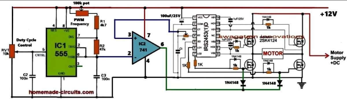
Referring to the above circuit diagram the proposed VFD circuit works in this way: The IC IRS2453 is configured as the basic full bridge or H-bridge inverter circuit which generates square wave output whose frequency is determined by the values of the Rt and Ct components of the circuit.
The output of this inverter is used to control the desired motor, whose speed need to be controlled as per the VFD rules.
In order to convert this square wave inverter into a sine wave VFD circuit, I have configured an adjustable SPWM generator stage using the IC 555 astable and an op-amp comparator.
The IC 555 is wired as a PWM astable circuit to generate the fast triangle waves as the carrier frequency which is fed to the non-inverting input of the comparator op-amp IC 741.
The slow triangle wave, which acts as the reference signal, is extracted from the Rt, Ct junction of the IRS2453 IC and is fed to the inverting pin #2 of the comparator IC 741.
The reference signal is intentionally derived from the Rt, Ct pin of the inverter IC to ensure that the SPWMs are perfectly synchronized with the set frequency of the inverter.
This frequency caan be set by adjusting the Rt resistor which can be a potentiometer.
The 741 IC compares the two input waveforms and generates an equuivaalent SPWM output waveform from its pin#6.
This output is integrated with the low side MOSFET gates of the H-bridge inverter IC so that the square wave operation of the inverter is transformed into an SPWM equivalent sine wave output.
Now, how does this basic sine wave inverter circuit turns into a variable frequency drive?
It is done by providing the adjustments for the frequency control and the RMS voltage control of the inverter output which controls the motor.
So with this sine wave inverter you can adjust the output RMS frequency by adjusting the duty cycle of the SPWM carrier wave and the frequency can be adjusted by adjusting the Rt resistor of the inverter IC which supplies the reference frequency for the SPWM.
How to Calculate Single Phase VFD Parameters
Input Power Calculations:
Power Factor (PF):
This is all about measuring how efficiently we are using AC power. It is extremely important for making sure we size the Variable Frequency Drive (VFD) correctly.
Apparent Power (S):
This represents the total power that’s supplied to the VFD, and it includes both real power and reactive power.
Formula: S = V * I
Real Power (P):
This is the actual power that the motor uses to do its work.
Formula: P = V * I * PF
Reactive Power (Q):
This is the power that bounces back and forth between the source and the load without doing any useful work.
Formula: Q = √(S² - P²)
Output Power Calculations:
Motor Power (Pmotor):
This refers to the mechanical power that comes out of the motor.
Formula: Pmotor = (Torque * Speed) / 9550 (for horsepower).
The constant 9550 is an important number we use in the formula that connects power, torque, and rotational speed when we’re working with the SI system of units.
Formula:
Power (kW) = Torque (Nm) * Speed (rpm) / 9550
What is its Importance
So, what is so important with the constant 9550? It comes from how we convert between different units of power (in kilowatts), torque (in Newton-meters), and rotational speed (in revolutions per minute). This number helps us to tackle the differences in these units, making sure that our equation works correctly.
- Power is measured in watts (W) or kilowatts (kW).
- Torque is measured in Newton-meters (Nm).
- Rotational speed is measured in revolutions per minute (rpm).
To get to that constant 9550, we need to think about a few things:
- Converting power from kW to W.
- Changing rotational speed from rpm to radians per second.
- Using the relationship that says power equals torque times angular velocity (power = torque * angular velocity).
When we do these conversions and simplify everything, we end up with that handy constant 9550 in our formula.
Remember:
This formula is specifically designed for the SI unit system. If you happen to be using different units, for example like horsepower or foot-pounds, then you will need to use a different conversion factor to make it work.
Motor Efficiency (η):
This is a measure of how well the motor converts input power into output power.
Formula: η = Pmotor / Pinput
VFD Sizing:
VFD Power Rating:
The power rating of the VFD needs to be higher than the apparent power of the motor's, so that it can handle any potential overloads without an issue.
Input Current:
We can calculate the input current based on the VFD's power rating and the input voltage specifications.
Output Current:
We also need to figure out the output current based on the power rating of the motor and output voltage.
Motor Speed Control:
Motor Speed (N):
The speed of an induction motor is directly connected to the frequency of the voltage we apply.
Formula: N = (120 * f) / P (where f is frequency and P is the number of poles)


Questions & Answers
I have a Jandy VSSHP270AUT variable speed drive pump. I am needing to know how to check the output of the VFD. The input power is 220. There are four connections of the bottom of the VDF that connects to the top of the motor. If i apply 220 ac power to the VFD, what should the power coming out at the four connects on bottom of the VDF be. There are four connects on the bottom.
One is connect to a red wire on the motor stator, one is blue, one is green and one is Blue. Once i apply power to the VFD, which color connection coming out of VFD is what as per where to check the voltage to see if the VFD is good or bad. I am trying to figure out if the VFD is bad or if the motor is bad. The motor seems to ohm out good but again i do not know how to check the VFD to see if it is good or bad. Your help would be most appreciated.
I think you should first check whether the VFD is getting proper 220V input and showing any error code. We cannot expect 220V AC between the four motor wires, as the output changes with the motor speed.
Also the wire colors alone cannot tell us which connections to check. The motor showing good resistance does not always guarantee it is OK. You will need a proper wiring diagram from the manufacturer to make the connections correctly…
Thank you very much for taking the time to answer my questions.
Hi,
Can you let me know where is the 220 / 120 V source?
What’s Motor supply +DC?
Where do the +12V come from?
Thanks in advance.
Hey, all these voltages are required for supplying the respective stages. 12V can be from an DC adaptor, 120V, 220V or motor supply can be from the AC mains or an inverter…
Thanks, very much, for your response.
But, where are the 120 / 220 V connected to the circuit? I can see where the motor is connected, but not the AC Mains.
And I don’t understand what “Motor Supply +DC” means.
Thanks in advance.
Thanks, I understand your problem…That source can be from a solar panel, rectified alternator DC or rectified DC 310V from mains supply…
“Motor Supply +DC” means the operating supply for the motor…
If you only have 120 or 220V coming from the public grid (AC), you need to rectify the 110V to 220V if it’s the same AC motor of that voltage. its ok?
Sir, I am very happy and thankful for your kind explanations given on the column. It helped me a lot to know the subject Electronics in a deeper way
Sir, I am very thankful to you if you pls kindly help me to build a SINGLE PHASE SOLAR VFD with an
Input Voltage: DC input range typically between 125V to 400V DC.
Output: Single-phase 200-240V AC, 50Hz. to operate a 0.5 hp monoblock water pump with
0.5 HP (0.37 kW) single-phase and with ampage of 3.8 A.
As it is safe to use a slightly higher 0.75 kW drive).
To run the pump on solar panels
Sir, requests you to pls kindly send circuit diagram and step by step explanation.
Thank you Sir.
Thank you so much Adam, for your kind words and I am glad my explanations helped you to learn more.
I will definitely create an article on your mentioned subject and also post a video soon, and let you know once it is done…
I realize this post and thread has been going for a while but I am looking into how to incorporate something like a VFD to control a resistive load and not for more than how it has soft-start using a ramp generator. I suppose what I am really looking for is a circuit that employs soft-start with variable timing to reach full on state.
The other approach I was thinking of is to have it current managed foldback operation where you could set the current limit and it would start soft and once it hits the limit, it would hold there till the resistive load reaches the crossing point and drops below the set threshold.
An example, for those wondering, would be the way a light bulbs resistance goes up as the filament warms up and thereby the load current drops.
The first thing I thought of was a VFD with soft-start.
VFD and PWM both can be an overkill for such a simple application. I think a simple current controlled regulator should do the job for you, as explained in the following article. Please check the transistorized or the MOSFFET version of the circuits. If you want any further modifications, please let me know…:
https://www.homemade-circuits.com/universal-high-watt-led-current-limiter/
I want more items to share
Can I use 220 volt single phase vfd to convert my normal one ton ac compressor to multi speed compressor and control with temperature sensor . If so please help me to design economical circuit for same 220 volt ac compressor.
Mostly yes, single phase VFD can be used with AC compressor, but only if the motor of the compressor is not a capacitor-start type. However, using temperature sensors you can directly control the AC compressor output without a VFD.
Hi,
I have a bench drill Cthat will not go slower than 450 rpm approximately. I want to drill large diameter stainless steel holes and at that speed the bits burn out. Other than getting special expensive bits I think it may be a reasonable option to use less than 50 Hz input for the 700 watt single phase motor. I am thinking something around 5 to 10 Hz range. Can you advise and are there plans that you can supply for the project.
Cheers.
Hi, I won’t recommend reducing the frequency, instead you can use a back emf based dimmer circuit as explained in the following post:
https://www.homemade-circuits.com/how-to-make-versatile-closed-loop/
Hi
220V AC of main voltage increasing to 310V DC after rectifying by Diode & capacitor
i have question , with 310V how to control 220v motor ?
Hi, the SPWM chopping from the 741 output across low side MOSFET gates will reduce the voltage to 220V or lower.
Hello Sir, how do I control the full H-bridge( with 2110) using Arduino in terms of code and connection?
Hello Everisto, you can use the following Arduino code and integrate it with your 2110 IC for implementing an H-bridge inverter:
https://www.homemade-circuits.com/simple-arduino-sine-wave-inverter/
I wish you did a demonstration of a single-phase project in Multisim using P type and N type Mosfets
Want complete guidence 3 phase vfd circuit diagram pcb ? Parts from where to buy
3 phase VFD circuit is recommended only for the experts, it may not be suitable for newcomers.
how are VFD’s applied to BLDC motors and what are the limits of “overspeed” based on frequency limits?
Thanks
Doug
Hi, Can this very useful circuit be used to drive a syncronous 220-240VAC motor?
I think it can be used to drive the specified motor.
Hi, I have couple of questions…
I would like to control a 1/2 HP single phase pump. The pump uses a permanent capacitor. Could I use a two phase VFD drive eliminating the need for the capacitor?
I would need to know the phase shift that the capacitor introduces.
I would also like to use a solar panel to drive the pump, varying the speed (freq.) and hence power according radiation…. the panel outputs 9.85 Amps @ 45.2 Volts (@ max radiation). I guess I would need a step up transformer to bring the voltage up to 220 V.
Hi, Sorry, I am not an expert with motors, so I am not sure whether a capacitor start motor can be controlled with a 2 phase VFD or not, or whether the capacitor can be removed or not.
If you want to use a solar panel, then certainly you will need to use an inverter to convert the solar panel DC into a 220 AC for the motor
hello, the circuits are tested? I did a simulation of the last schematic and it doesn’t work, included with the optocouplers to drive the mosfets
Hello, you must do the simulation in a step wise manner, first try simulating the 555 section, then the 4017 section.
The 555 and the 4017 sections are perfectly tested OK, but the mosfet section has problems, which might need some corrections. I have added the necessary warning message with the diagram.
can updated circuit with irs2453 be directly used for 250-300 v. or it need to modify as stated in comments using 4N25 optocoupler
If you are using IRS2453 IC with 4 N channel mosfets then you can easily use 300 v directly with the mosfets, no optocouplers will be required.
Hi Swagatam,
thank you very much for this interesting article!
I’d like to build a VFD for a 240V universal motor of about 1 kW; it might peak at 40A during startup and at low speeds/high loads and I was not able to find suitable mosfets, since I’m also concerned that back emf can reach more than 600V.
Do you have any suggestion for suitable mosfets P/N (or mosfets configuration), and do you believe I should use some snubber network or the like?
I’d like very much to hear any suggestion from you, thanks!
Thank you LCU,
For the P channel you can try FQP4P40 mosfets and IRF740 for the N channel. However, there seems to be a mistake in the last diagram.
The source voltage for the P channel mosfets is 310V, and the gate voltage is 12V which cannot work. For switching OFF the P channel effectively, its gate voltage must be same as its source voltage.
Therefore we may have to modify the H bridge section in the last diagram through opto couplers for effective switching of the P channel mosfet as shown in the following example design:
https://www.homemade-circuits.com/wp-content/uploads/2021/02/4047-solar-transformerless-inverter-compressed.jpg
FQP4P40 has a max Vgs of 30V or -30V. When the optocoupler shorts the gate to ground you will have around 0V at the gate and 310V at the source. Would this not make Vgs -310V and destroy the mosfet?
You are right! I think this can be rectified by adding a 15V zener diode across the gate/source pins of the P channel mosfets.
whats the function of bc 557 in the last circuit ? can it or anything else be removed to simplify even more it ?
BC557 allows the IC2 555 to work with a constant current which ensures the PWMs are always consistent regardless of Dc supply variations
Dear Sir,
I wish to make your last drawing…..using 8 mosfet…it is simple from other…So pl give mosfets number…8 nos..
Hello Anilkumar, the upper mosfets can be any 400 V P-channel mosfets, and the low side mosfets can be any 400 V mosfets.
Sir,
I wants single phase 230v 50 hz 2800rpm circuit…is it possible for 2800rpm pump…
Yes that’s possible by adjusting the output frequency to 50 Hz.
Sir,
I will try this method Surely…..
Sure Anil, you can try it.