In this post I have explained a simple relay changeover circuit for extracting single phase AC from a three phase AC source irrespective of the condition whether all the three phases are present or not. The circuit was requested by Mr. Biannz.
Technical Specifications
hi sir please i need something I've been searching everywhere but not avail so please I'm appealing to you if you can do it for me, this is special request, The thing is in my country we have 3 phase meter and single phase meter so if you use single phase meter you are able to get one phase AC power and negative from the electricity-pole, But sometime one phase go off and also low voltage problems exist, so sir what i am requesting you is to design for me a 3 phase changeover which will bring all the 3 power from the electricity pole for the attached single phase meter so that when any one phase power goes off or low current then it changes to another phase.I have tried one such circuit for changing the second alternate phase when one phase goes off, however when it comes back again while the other one is not off which becomes very dangerous. so i will be glad if you can design me one 3 phase changeover circuit. thank you sir looking forward to hear from you.
The Design
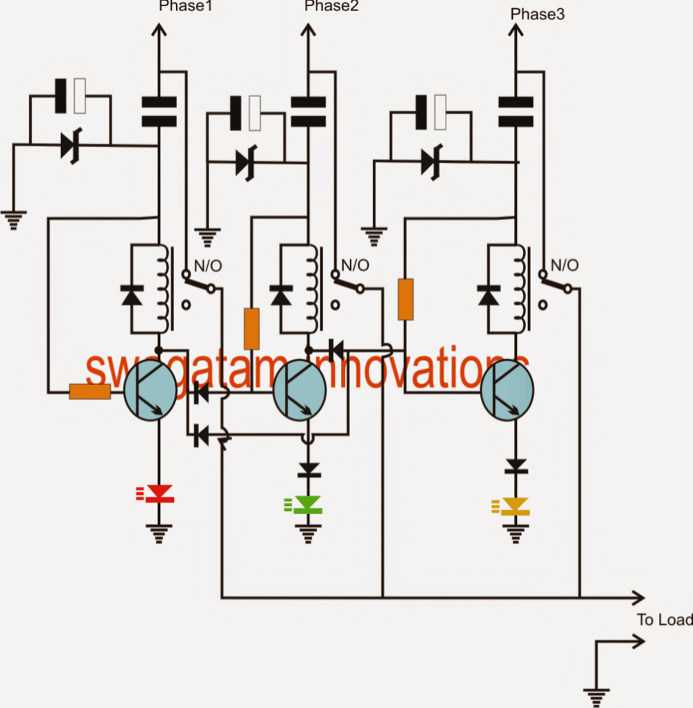
The circuit of the proposed changeover circuit which can be used for getting a single phase AC from a three phase AC source even with missing phases is shown the following diagram.
Although the circuit looks technically correct and safe, it won't respond to low voltage or brownout conditions, so perhaps additional stages would be required for facilitating this feature.
As can be seen the circuit would be able to supply a single phase power to the load no matter whether all the phases are present or if a couple of them are missing and also irrespective of the phase serial number.
Suppose all the three phases are present, this would allow the left transistor relay to stay activated while keeping the other two stages switched OFF.
With only phase1 present, the same would be applied as above.
With phase2 and phase3 present and phase1 off, the center transistor stage would operate while the remaining would remain switched OFF.
With only the third phase present and the other two missing would activate the right most relay stage while keeping the other two switched off.
Therefore under all situations the load would be allowed to access the single phase power from the given 3 phase source.
The ground indicated connection must be terminated to the pole as suggested by Mr.Biannz.
Circuit Diagram
Parts list
All resistors are 10k, 1/4 watt
All non-polar capacitors = 105/400V
All polar capacitors are = 100uF/25V
All zener diodes are = 12V/ 1watt
All transistors are = BC547
All relays are = 12V/spsdt, 12amp/400mA
All rectifier diodes are = 1N4007
WARNING: THE ABOVE CIRCUIT IS NOT ISOLATED FROM MAINS AC AND ALL THE CIRCUIT POINTS COULD BE AT LETHAL MAINS POTENTIAL, EXERCISE EXTREME CAUTION WHILE MAKING IT, AND DO IT AT YOUR OWN RISK.
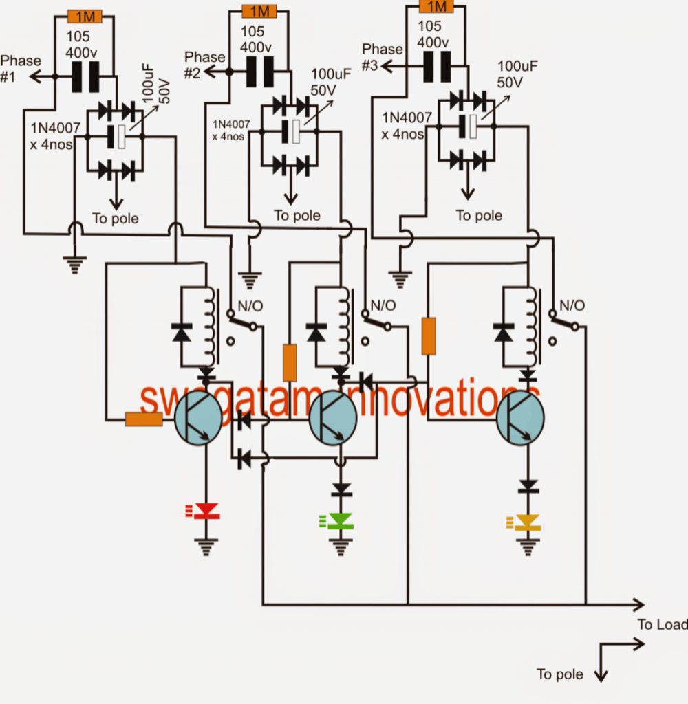
Upgrading the above Circuit
The following single phase voltage from three phase voltage source circuit shows how the above earlier circuit can be upgraded using a bridge network circuit for better response.


Questions & Answers
SIR CONSIDERING THE SECOND CIR DIAGRAM, I THOUGHT A 400V RATED CAPACITOR WOULD BE THE BEST FOR FILTERING BEFORE SCALING IT DOWN WITH ANOTHER ELECTROLYTIC CAPACITOR OF APPROPRIATE VOLTS IN PARALLEL WITH THE RECTIFIED DCV. A PROSPEROUS NEW YEAR TO YOU IN ADVANCE SIR!
Thank for the feedback Moses, that’s correct.
Wish you too a prosperous New Year
ok if you say so no problem but i well be happy if you can try and build it you have design it perfectly but what i was expecting it should be it did not so unless you try it your self then you will see if im correct or not thank you sir.
The above circuit is designed by me, and just by looking at it I can say that it will work. If you think there's a problem you can point it out in the circuit, I'll check it.
thank you sir i have modified this circuit it very sensitive i have remove all the collectors diode including the base diode as-well i replace it with another relay it work very well as i was expecting. i trying to upload it to this blug but i couldn't.
Biannz, it's OK if you have modified it as per your liking, but I don't recommend any modifications in the last diagram.
For me the last diagram is perfectly correct and does not require any changes.
sir this circuit is very simple so how can i make a mistake for almost two weeks i cannot see the wrong connection i build it as the way it is. please indicate the pins of the transistors for me BC547
please see the datasheet of the transistor to find the exact pin out details.
sir please i didn't connect the bridge circuit with the pole ground i connected all the pole gnd together, and all the gnd of the circuit together,now if i connect phase 1 it relay switch but phase 2 and 3 don't operate i think that is correct? if i disconnect phase 1 and connect phase 2 it relay dont switch but phase 1 relay get switch same happen to phase 3.
how can phase1 relay switch ON when phase1 is removed, from where the phase one transistor relay get the voltage to switch ON??
….that's a big mistake.
sir i have to troubleshoot it my self i did but one thing is i have build them in stages the relay work but if i add all the ground together it don't work,sir my understanding is when all the phases are available one relay should work and if of it gos off another relay switch if the phase that went off returns it relay should stay off on-till the rest phases go off before it start working same should happen to any of the phases lets me say it should be random.thank you sir and for give me if something i said is wrong.
The bridge terminal which is indicated to be connected to the pole should NOT be with the ground of the circuit.
The bridge/circuit ground is not connected with the pole.
Two relays will NEVER be activated together under any circumstance, so it's completely safe according to me.
read the base connections of the middle and the right hand transistors, understand them how these will be grounded and stopped from conducting when the collectors of the other relevant transistor are active.
sir you know what i have change nothing in this circuit i build it according to your rule i gave this circuit to one of friend his is very good in electronic he having same problem
Please understand the circuit functioning stagewise, and troubleshoot it yourself, that's the right way to go.
I think there should be priority in the switching of the relays whereby the most preferred phase switches on and carries the load while others should be on standby in case one phase fails. The circuits above entails all phases being on and feeding the load simultaneously which is not good. The n/c contacts of the relays should be put to work just like it applies in automatic voltage stabilizer. Thanks!!
yes sir all the led illuminate but only the left side of the relay operate 2 and 3 don't work sir i prefer that you should have a little bit of time to build it and see whats the problem is cos this circuit is very dangerous if it didn't build well. thank you sir for your kindness im very appreciate.
biannz,
the circuit is absutely correct, yes it's dangerous and that's why you should take some time to understand it and only then build it, if you do it without understanding it you will never succeed,
moreover the design is super simple, even a layman would understad it at first glance.
with all the phases present, only ONE LED should illuminate at a time, if all the LEDs are illuminating means something's wrong in your design
see the bases of the middle and the right transistors, those are connected to collector of the left transistor, if the left transistor is operating how would the middle and right transistor possibly conduct because there bases would be grounded through the left transistor collector., please research this and explain this to me.
sir i add another diode but it don't work sir
are the LEDs illuminating? what is the response of the LEDs with regard to the ACs across the three inputs?
pls verify these and tell me the results
sir please i have a friend his very good in PCB lay out so gave this circuit to him,he use EAGLE SOFTWARE he did it as it is all the led light up sir the problem is when i pug phase 1 it switch correctly if i connect phase 2 first relay switch only one relay work when connect all the phases one by one another thing is when i connect phase 1 relay work and if connect phase 2 it switch while phase 1 is not off i think it shouldn't happen that way cos it very dangerous?
biannz, connect diodes in between the relay coil and the collectors of each transistor as shown in the last diagram, and recheck the results
sir i think you don't get me right what mean is im using a extension board so i take phase from the circuit i plug it to the extension board i did it one by one only the left side of the circuit which is phase 1 relay get switch so if i remove it and if plug phase 2 from the circuit the green led light up but relay don't switch same happen to the lats relay which is right side i think it suppose to switch on one after the other? thank you sir.
bianzz, if the green LED or the yellow led is lighting then the relevant relays must also operate, there could be some fault in you connections, pls check it properly.
also note that only one led must be lit at a time, if more than one are illuminating would indicate a fault in the circuit.
sir i connect it sir im using only 1 phase for trying
if you are using one phase then you should make it common on all the phase inputs and then remove randomly to see the results.
thank you sir i have build it but only phase 1 relay switch the other 2 relay don't switch,if i power the circuit i got out put AC power but when i switch off phase 1 the 2 relay did not switch so no power at out put help me sir thank you sir.
biannz, did you connect phase2 and phase3 also…..please do it by understanding the circuit functioning completely, otherwise you may never succeed and could create short circuits ad fire hazards.
Dear Mr Swags
It is possible to use only 3 relays (of 2 Contacts each). We are not need the electronic components. Isn't it?
Dear Sasa,
how could that be implemented, can you explain it please??
ok sir thank you i will go to electronics shop tomorrow and buy the pats so when im fish i will let you know,sir i tried to send you pic but it couldn't go through can you give me your email address i think that would be easier cos i tried the Google drive but not.
my email IDs can be found in the "contact" link
sir i have connect the led but it not i remove the ziner diode still and i use bridge rectifier after the 105/400V capacitors for each channel. it did not g through sir can you please republish it with full bridge rectifier for me sir thank you.
biannz, please check out the upgraded design…
Please sir, i am still confuse on how to use transistors to amplify current. How do i do that? And what polarity of transistor(NPN or PNP)? What transistor configuration do i use(common base, common collector or common emitter)? What would b the base resistance? These are the questions that i need answers on. Assumin my circuit is producing 1amp and i need 1.5 or 2amp, hw do i go about it? But dont include buck ICs lyk L7805 in your explanations because my circuit has no L78xx series. Please help me sir. Thanks
Sorry Jideofor, although transistors can be used as current amplifiers, they cannot generate more than the source current.
you cannot generate 2amps from a 1.5amp source through any device.
sir im very appreciate for your help and kindness sir is not that im bordering you, sir please can you take a little bit time and build this circuit so that you can see what the problem is cos i did my effort and i did as you said but it still don't work,sir please help me becos i want this cir circuit.
bianzz, please first do as sugested in my previous comment
As shown in the figure, connect an led in series with the emitter of the transistors, if the LED lights up but the relay does not operate would mean that the capacitor current is not sufficient enough for triggering the relay…in that caes you can either remove the zener diode to see if that helps, or use bridge rectifier after the 105/400V capacitors for each channel.
sir thank you im very glad about your kindness,sir i have tried the mentioned parts but still it don't work sir my AC power from the pole is very strong.sir please can you check the circuit maybe there is something wrong cos im going crazy.
connect an led in series with the emitter of the transistors, if the LED lights up but the relay does not operate would mean that the capacitor current is not sufficient enough for triggering the relay…in that caes you can either remove the zener diodeto see if that helps, or use bridge rectifier after the 105/400V capacitors for each channel.
Hola SWAGATAM, mi pregunta es: si la corriente que pasa por los LED es suficiente para conectar los relés.
thank you sir,i want to use 15v ziner diode and 1000uf/25v cap,and replace 1815 transistor in place of bc547 sir please check it for me if it good to do that? i have this relay JZC-20F (4088) 10A DC12 RELAY.
1815 pinouts are different to BC547….note
yes biannz, you can go ahead with the mentioned parts
sir please is there any solution that you can do again? sir please im asking can tee me what the ziner diode doing in the circuit?
zener diode is for ensuring a safe 12V DC supply to the circuit and the relay
sir i use 400 ohm relay but still non of them operating or activated sir how many volt this circuit need? sir all the three relay common have to connects together,and all the power also should connects to each relay n/o or it should be connects to n/c right? cos i can see that it connected to n/o all of it have activated isn't dangerous or sir all the relay have to activate one after their other when each phase gos off? thank you.
only one relay will conduct at a time so there's nothing to worry according to me, may be your electricity-pole is not giving the optimal neutral supply for the circuit and that's why it's not working.
thank you sir i finally build it sir i want to ask you that when all phases is present the relay have to o prats i mean it have to move cos the relay don't switch and also all the negative connection or line received power sir should all the 7 negative shown there have to connects to pole which come from the electricity? sir i did not connects all the phases i only used single phase to tested,or sir all the 3 relay have to stay there n/c? thank you.
One of the relays will be always in a operative condition.
If one of the relays is not operating could mean the capacitor power is not satisfying the relay coil current requirement.
you must use a 400 ohm relay to get a proper response from a 105 cap.