The presented 3 phase VFD circuit (designed by me) can be used for controlling the speed of any three phase brushed AC motor or even a brushless AC motor. The idea was requested by Mr. Tom
Using the VFD
The proposed 3-phase VFD circuit can be universally applied for most 3-phase AC motors where the regulation efficiency is not too critical.
It can be specifically used for controlling squirrel cage induction motor speed with an open loop mode, and possibly also in the closed loop mode which will be discussed in the later part of the article.
Modules Required for 3 Phase Inverter
For designing the proposed 3 phase VFD or variable frequency drive circuit the following fundamental circuit stages are essentially required:
- PWM voltage controller circuit
- 3 phase high side/low side H-bridge driver circuit
- 3 Phase generator circuit
- Voltage to frequency converter circuit for generating V/Hz parameter.
I have explained the functioning details of the above stages with the help of the following explanation:
A simple PWM voltage controller circuit can be witnessed in the diagram given below:
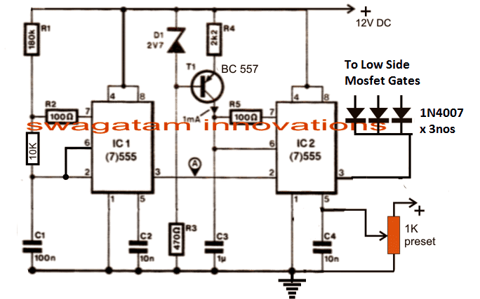
The PWM Controller
I have already incorporated and explained the functioning of the above PWM generator stage which is basically designed for generating a varying PWM output across pin3 of IC2 in response to the potential applied at pin5 of the same IC.
The 1K preset shown in the diagram is the RMS control knob, which may be appropriately adjusted for acquiring the desired proportionate amount of output voltage in the form of PWMs at pin3 of IC2 for further processing. This is set to produce a corresponding output that may be equivalent to the mains 220V or 120V AC RMS.
The H-Bridge Driver Circuit
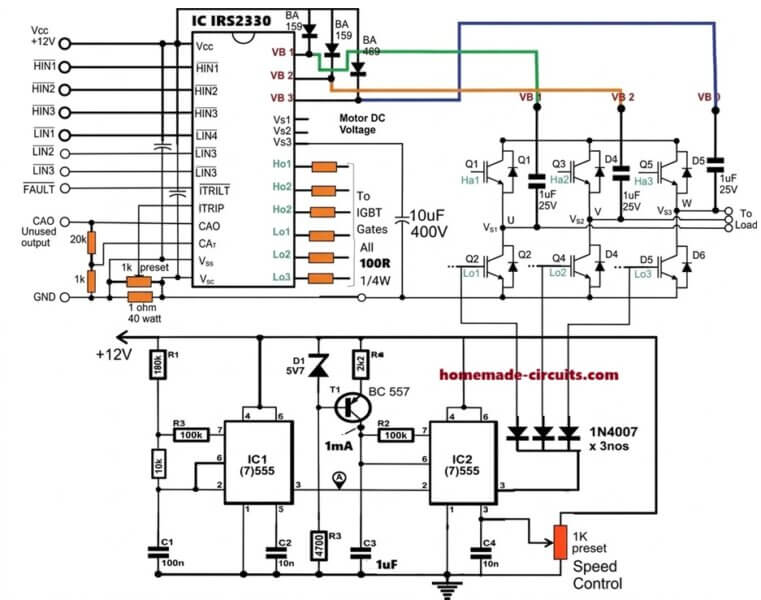
The next diagram below shows a single chip H-bridge 3 phase driver circuit using the IC IRS2330.
The design looks straightforward as most of the complexities are handled by the chips in-built sophisticated circuitry.
A well calculated 3 phase signal is applied across the HIN1/2/3 and LIN1/2/3 inputs of the IC through a 3 phase signal generator stage.
The outputs of the IC IRS2330 can be seen integrated with 6 mosfets or IGBTs bridge network, whose drains are appropriately configured with the motor which needs to be controlled.
The low side mosfet/IGBT gates are integrated with the IC2 pin#3 of the above discussed PWM generator circuit stage for initiating the PWM injection into the bridge mosfet stage. This regulation ultimately helps the motor to gain the desired speed as per the settings (via the 1 k preset in the first diagram).
In the following diagram we visualize the required 3 phase signal generator circuit.
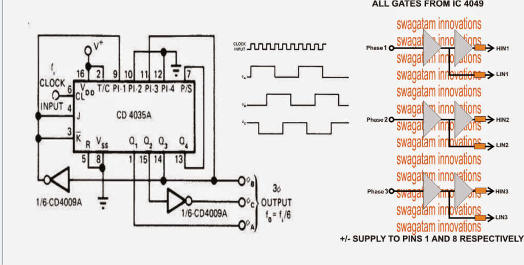
Configuring the 3-Phase Generator Circuit
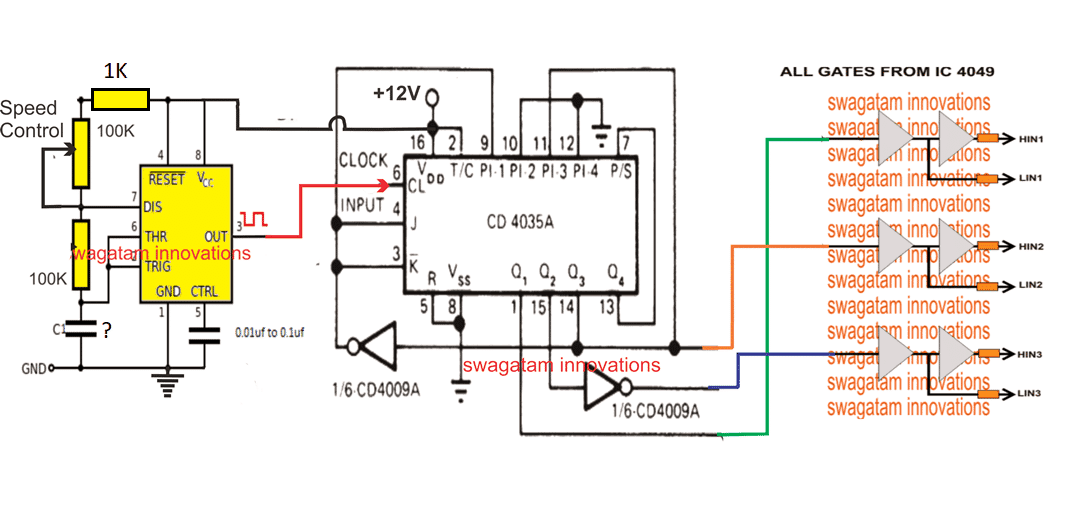
The 3 phase generator is constructed around a couple of CMOS chips CD4035 and CD4009 which generates accurately dimensioned 3 phase signals across the shown pinouts.
The frequency of the 3 phase signals depends on the fed input clocks which should be 6 times the intended 3 phase signal. Meaning, if the required 3 phase frequency is 50 Hz, the input clock should be 50 x 6 = 300 Hz.
It also implies that the above clocks could be varied in order to vary the effective frequency of the driver IC which in turn would be responsible of varying the motor operational frequency.
However since the above frequency alteration needs to be automatic in response to the varying voltage, a voltage to frequency converter becomes essential. The next stage discusses a simple accurate voltage to frequency converter circuit for the required implementation.
How to Create a Constant V/F Ratio
Typically in induction motors, in order to maintain an optimal efficiency of the motor speed and toque, the slip speed or the rotor speed needs to be controlled which in turn becomes possible by maintaining a constant V/Hz ratio. Since the stator magnetic flux is always constant regardless of the input supply frequency, the rotor speed becomes easily controllable by maintaining the V/Hz ratio constant.
In an open loop mode, this can be done roughly by maintaining predetermined V/Hz ratios, and implementing it manually. For example in the first diagram this may be done by suitably adjusting the R1 and the 1K preset. R1 determines the frequency and the 1K adjusts the RMS of the output, therefore by suitably adjusting the two parameters we can enforce the required amount V/Hz manually.
However to get a relatively accurate control of an induction motor torque and speed, we have to implement a closed loop strategy, wherein the slip speed data needs to be fed to the processing circuit for an automatic adjustment of the V/Hz ratio so that this value always remains near about constant.
Implementing the Closed Loop Feedback
The first diagram on this page can be suitably modified for designing the closed loop automatic V/Hz regulation as shown below:
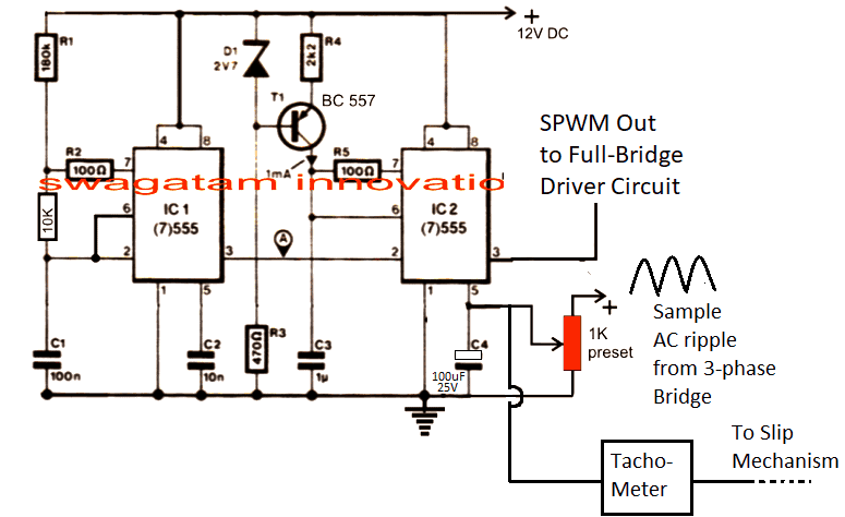
In the above figure, the potential at pin#5 of IC2 determines the width of the SPWM which is generated at pin#3 of the same IC. The SPWM are generated by comparing the mains 12V ripple sample at pin#5 with triangle wave at pin#7 of IC2, and this is fed to the low side mosfets for the motor control.
Initially this SPWM is set at some adjusted level (using 1K perset) which triggers the low side IGBT gates of the 3-phase bridge for initiating the rotor movement at the specified nominal speed level.
As soon the rotor rotor begins rotating, the attached tachometer with the rotor mechanism causes an proportional additional amount of voltage to develop at pin#5 of IC2, this proportionately causes the SPWMs to get wider causing more voltage to the stator coils of the motor. This causes further increase in the rotor speed causing more voltage at pin#5 of IC2, and this goes on until the SPWM equivalent voltage is no longer able to increase and the stator rotor synchronization attains a steady-state.
The above procedure goes on self adjusting throughout the operational periods of the motor.
How to Make and Integrate the Tachometer
A simple tachometer design can be seen in the following diagram, this could be integrated with the rotor mechanism such the rotational frequency is able to feed the base of the BC547.
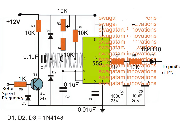
Here the rotor speed data is collected from a hall effect sensor or a IR LED/Sensor network and is fed to the base of T1.
T1 oscillates at this frequency and activates the tachometer circuit made by appropriately configuring an IC 555 monostable circuit.
The output from the above tachometer varies proportionately in response to the input frequency at the base of T1.
As the frequency rises the voltage at the extreme right side D3 output also rises and vice versa, and helps to keep the V/Hz ratio to a relatively constant level.
How to Control Speed
The speed of motor using constant V/F can be achieved by altering the frequency input at the clock input of IC 4035. This can be achieved by feeding a variable frequency from a IC 555 astable circuit or any standard astable circuit to the clock input of IC 4035.
Changing the frequency effectively changes the operating frequency of the motor which correspondingly lowers the slip speed.
This is detected by the tachometer, and the tachometer proportionately reduces the potential at pin#5 of the IC2 which in turn proportionately reduces the SPWM content on the motor, and consequently the voltage for the motor is reduced, ensuring motor speed variation with the correct required V/F ratio.
A Homemade V to F Converter
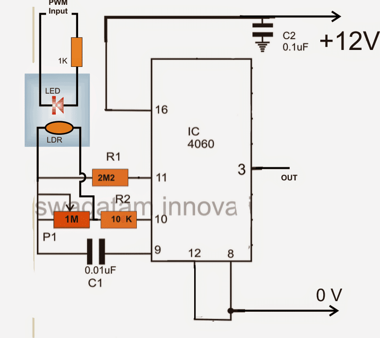
In the above voltage to frequency converter circuit a IC 4060 is used and its frequency dependent resistance is influenced through a LED/LDR assembly for the intended conversions.
The LED/LDR assembly is sealed inside a light proof box, and the LDR is positioned across a 1M frequency dependent resistor of the IC.
Since the LDR/LDR response is fairly linear, the varying illumination of the LED on the LDR generates a proportionately varying (increasing or decreasing) frequency across pin3 of the IC.
The FSD or the V/Hz range of the stage could be set by appropriately setting up the 1M resistor or even the C1 value.
The LED is voltage is derived and illuminated through the PWMs from the first PWM circuit stage. It implies that as the PWMs vary, the LED illumination will also vary which in turn would give rise to a proportionately increasing or decreasing frequency at pin3 of the IC 4060 in the above diagram.
Integrating the Converter with VFD
This varying frequency from the IC 4060 now simply needs to be integrated with the 3 phase generator IC CD4035 clock input.
The above stages form the main ingredients for making a 3 phase VFD circuit.
Now, it would be important to discuss regarding the DC BUS required for supplying the IGBT motor controllers and the setting up procedures for the entire design.
The DC BUS applied across the IGBT H-bridge rails may be obtained by rectifying the available 3 phase mains input using the following circuit configuration. The IGBT DC BUS rails are connected across the points indicated as "load"
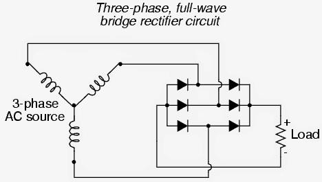
For a single phase source the rectification may be implemented using standard 4 diode bridge network configuration.
How to Set Up the proposed 3 phase VFD circuit
It may be done as per the following instructions:
After applying the DC bus voltage across the IGBTs (without the motor connected) adjust the PWM 1k preset until the voltage across the rails become equal to the intended motor voltage specs.
Next adjust the IC 4060 1M preset in order to adjust any of IC IRS2330 inputs to the required correct frequency level as per the given motor specifications.
After the above procedures are completed, the specified motor may be connected and supplied with different voltage levels, V/Hz parameter and confirmed for an automatic V/Hz operations over the connected motor.



Questions & Answers
اريد صورة لكامل المشروع تجمع الدخل ودائرة التحكم والخرج في صورة واحدة
hello
good day
we are developing testing proposes in house used, IGBT base three phase regulator ,
1700 Voltage, 500amp
guided us controller and IGBT
Hi, do you want it to be an Arduino based design, or just an analogue version??
Dynamic Braking Resistor (DBR) or Dynamic Braking Unit (DBU) is an essential electrical component used in various industrial applications to safely dissipate extra energy produced when an electric motor or other devices are braking. When a motor slows down or stops, it behaves like a generator, creating a reverse electrical current called back electromotive force (EMF). If this energy isn’t managed properly, it could cause damage to both the motor and the connected drive system.
To handle this excess energy, dynamic braking is used in systems like elevators, cranes, electric trains, and vehicles—basically any equipment that requires frequent, controlled slowing down or stopping. In most setups, the DBR works alongside a Variable Frequency Drive (VFD), which is a motor-controlling system that helps regulate this braking process. In this guide, we’ll walk through how to connect a Dynamic Braking Resistor to a VFD.
Step-by-Step Connection Guide
Identify the DBR Terminals in the VFD:
Most VFDs come with specific terminals dedicated to connecting a DBR. Typically, there are two terminals, one for the positive connection and another for the negative. These terminals are usually labeled “+” and “-” or more commonly as “DC+” and “DC-”. In the wiring diagram provided, you’ll see that the VFD has clearly marked “DC+” and “DC-” terminals.
Connect the Input of the DBR to the VFD:
You’ll then connect one terminal of the DBR to the “DC+” terminal on the VFD and the other DBR terminal to the “DC-” on the VFD. This setup allows the DBR to absorb the extra energy generated by the motor while braking.
Consider a Resistor Contactor or Brake Chopper:
In some VFD setups, you might need an additional component like a resistor contactor or brake chopper to control how the DBR is connected to the VFD. A brake chopper is a solid-state device that regulates the flow of energy between the VFD and the DBR. If your system includes one, make sure to follow the manufacturer’s directions for proper installation.
Configure the VFD’s Parameters:
To enable the DBR to function properly, you’ll need to adjust some settings on the VFD. This might include turning on dynamic braking mode, entering the correct resistance value of the braking resistor, and configuring torque or current limits. These settings vary depending on the model of your VFD and the specific needs of your application.
Always follow the manufacturer’s instructions for both the VFD and DBR when making connections and adjusting parameters. Incorrect setup or misconfigured parameters can result in system errors or even damage the equipment. Consulting the user manuals is highly recommended.
How Dynamic Braking Works
When the motor is slowing down or stopping, the VFD senses this and switches to dynamic braking mode. Instead of just cutting power to the motor (as in normal stopping), the VFD directs the surplus energy generated during braking to the DBR.
In this system, the DBR is connected in parallel with the VFD’s DC bus and acts as a load that absorbs this excess energy. The DBR has a high-power rating and specific resistance designed to convert the energy into heat safely.
Because dissipating energy in the form of heat can cause the DBR to overheat, they are usually equipped with cooling systems like heatsinks or fans to keep the temperature down.
Once the braking process is complete, the VFD switches back to its normal mode, resuming its role of supplying the right amount of voltage and frequency to the motor for smooth operation.
In summary, a DBR ensures that the energy generated when slowing down a motor is safely and efficiently managed, preventing damage to the motor and other electrical components.
Thank you Jitu,
you can try the following circuit:
Sir, Namaskar.
I am technician
I won’t full circuit diagram of DBU
(DYNAMIC BRAKING UNIT ) & DBR for three phase motor.
My email : jvpateljv@gmail.com
Thank you.
Hi Jitu,
Can you please provide more details on how dynamic braking is supposed to work, about its working concept?
I will try to figure it out…
Dear Sir
IC IRS2330 is not available in Sri Lanka. Is it available in India. Otherwise manufacturers sells it in large quantities only.
Grateful for your help and guidance.
Regards
Pradeep
Thank you Pradeep,
The IC is available in India, or you can also try getting it from popular online stores like amazon or Ebay.
Dear Sir, what is the recommended IGBT for 110VX3 phase motor? Can we use IXSK 80N60B for this? Grateful for your advice.
Hello Pradeep, can you please provide the power rating (wattage) of the motor, I will try to figure it out…
Could you provide me a complete (composite) and clear diagram for the circuit.
The full diagram can be too large to fit on the screen, therefore I have shown the stages separately.
Do you have the circuit board & components for this as DIY project?
Sorry, PCB is not available for this project.
Hi Sir,
My circuit is almost completed earlier but due to my father’s cervical spine surgery I unable to take field trial bcz without his help and guidance it is risky (it is High voltage and high current power supply).
Now he is comfortable to do this.We will be planned it in this week.
after taking the same testing I will be shared all details to you.
I have required a information before it about heat sink. If I connected 5HP 3 phase submersible motor to the circuit load which heat sink I should be required?
Thank you Sanika, for updating the information!
Glad to know your father has recovered from the illness and is doing good.
Regarding the heatsink, it can be difficult to assume how large the heatsink should be. It can be verified only though some practical testing. Initially you can use a medium sized finned type heatsink and check whether it gets too hot or not. If it gets too hot you may have to increase the size and so on.
Hi sir,

Getting the oscilloscope will take some time (2-3 days) so I decided to work on the above project . I have first built CD4035, CD4009 and CD4049 circuit so can you guide me in detail how should I check it?
Without clock input (Pin 6) is it possible to check it?
CD4009 IC Pin1 VCC, Pin16 VDD, both have to be connect +12vdc And if only Pin16 have to required +12v then what is about Pin1?
Pin8 connected to GND (-) and Pin 7,9,11&14 also connected to GND. Pin 6,10,12&15 kept free.
Pin3 used for input from CD4035 pin14.
Pin2 used for output and connected to to CD4035 Pin 3
Pin 5 used input from CD4035 pin 15
Pin4 used for out put to the input of CD4049 pin 7
CD4035 Pin 1 connected to Input of CD4049 pin3
CD4035 Pin14 and CD4009 pin2 connected to CD4049 input Pin 5.
Sorry to bother you.
Thanking you
Hi Sanika,
For this project also you will need an oscilloscope.
The IC 4009 VDD and VCC is a bit confusing. According to the datasheet, it says “CONNECT VCC TO DTL OR TTL SUPPLY, CONNECT VDD TO COS/MOS SUPPLY”
I think 4009 can be also replaced with a 4049 IC which also has NOT gates. So you can use two 4049 ICs. Use 6 gates from one 4049 IC to connect with the HIN and LIN inputs of the 3 phase inverter IC, and use only two gates from the other 4049 IC to connect with the 4035 IC.
You can use any two gates from the 4049 IC to work with the 4035 IC. For the remaining 4 gates make sure to connect their inputs with the ground line, outputs can be kept open or unconnected.
Hi Sir, Good morning.
I made a oscilloscope with Raspberry Pi Pico (Scoppy Android App) it’s work good. plz check wave image of CD4035 and CD4049 output. I used CD4049 instead of CD4009 means 02 nos CD4049 as per your suggestion.
I check each output signal wave
https://drive.google.com/file/d/1DGsYktKpBYdQn1zGGlL9u3ZurAnJWk1e/view?usp=drivesdk
Plz check and suggest what can i do next?
Can i built inverting circuit with IR2130 IC which is similar to IRS2330?
Thanking you
Good Morning Sanika,
That looks good and a correct waveform from the respective ICs. However it is also important to check the 120 degree shifts from the 3 phase outputs of the CD4035 IC. How will you check and confirm that?
Yes IR2130 IC will also work fine.
Hi Sir,

Plz advice about resistors at output HIN 123 and LIN 123 after CD4049.
I used 1k 1/4 watt.
Thanking you
Hi Sanika,
Actually resistors are not required at HIN, LIN inputs since they are all high impedance inputs, but if you have used 1K resistors there’s no problem, it’s fine.
Hi Sir,
Sorry since there was a wedding ceremony at home so I could not do any work for so long. Now I have started working again. I have built and tested this circuit but all the igbt base is getting supply just not HO2. Frequency is available in all bases except HO2 pin 24. Also in IR2130 this HO2 Pin 24 is not getting frequency and Igbt is getting hot. Please advise on this.
Hi Sanika,
Did you supply the 3 phase signal to HIN and the LIN pins correctly? You must check the 3 phase signals with an oscilloscope and they must be 120 degrees phase apart. Also the Vcc pin of the IC must get 12V, I hoe you have connected that.
Sir
If it is ok plz suggest which is next stage?
Sanika, The 3 phase inverter needs a 3 phase signal, did you check the 3 phase 120 degree phase shift for the 3 phase generator output?
Hi Sir,
Yesterday it was checked at our technical institute with the oscilloscope. It is generated 3 Phase signal 0,120 and 240 degree but I couldn’t able to click pic.
I checked HIN ,and LIN output of CD4049.
Hi Sanika,
If you are able to get the 3 phase square wave waveform across the outputs of the 4049 NOT gates then the basic IRS2330 inverter circuit should work, because the IRS2330 circuit was referred from the datasheet of the IC.
Alternatively you can also try the following concept if possible, it looks much easier:
Sir
I am using IR2130 and 25N120 IGBT .it’s all ckt done and tested all IGBT output same (Input 12vdc and output 12 vac)
For clock input used frequency generator which earlier I made for test the my old oscilloscope.
I tested it upto 48vdc and output also get same.
Plz suggest what will be next stage?
Thanks
Sanika,
Is your 3 phase inverter circuit working OK? Are you getting 48V 3 phase output? Please confirm this first.
Hi Sir,
Yes my 3 Phase inverter ckt working.
When I input 24vdc to IGBT I got 24 vac at all 3 output
Then I input 48vdc that time I got 48vac at all 3 output.
Sanika, That is very good, however you must confirm the 3 phase output with a load. After that we can proceed to the IC 555 speed control stage.
Hi Sir,
That means I have to connect it with 3 Phase motor and input dc voltage.
How much dc voltage I should be input? Which filter capacitor (e.g. 150uf/450v , 330uf/450v or 220uf/450v) I have to connect in dc bus to filter?
I will be generate dc voltage from single phase 220v with KBPC3510 Bridge rectifier.
Is it possible? Plz advice about it.
Hi Sanika,
First test with 3nos 24V or 12V bulbs using the same DC input as the bulb rating.
If it works then only you can try 310 V DC from 220 V AC as the bus voltage and a 3 phase motor, for the actual testing.
For the filter capacitor I think 220uF/450V or 330uF/450V will be quite enough.
Good morning Sir,
I currently use the following ckt to test the circuit. Because I was not satisfied with the IC555 circuit I made earlier, its square wave was not satisfactory and after setting the CLOCK input of CD4035 to 220-230 Hz frequency, it was getting 50Hz after CD4049, like Fluctuations were happening, so I prepared it with the reference of your second article and the result was very good
Now there is no fluctuation and the waveform is also very smooth.
After setting 300Hz frequency, finally exactly 50Hz, 50% duty cycle and 20ms time period are obtained.
I used C- 0.1uf
R1- 10k potentiometer
R2- 100k potentiometer so it was easy for me to set.
Thank you very much indeed. I am continuously learning a lot from you and thank you again for explaining in difficult times.
Good Morning Sanika,
I am always glad to help, and I am also glad your 3 phase signal generator is working perfectly for you.
All the best to you.
Feel free to ask if you have any further questions.
Hi Sir,
Tested 12vdc with 3 lamp on each phase. Plz check the attached pic.
https://drive.google.com/file/d/12iCguc41pjvaPigaI585zBuYmjquIO63/view?usp=drivesdk
Voltage is dropping around 1v to 1.5 volt in each phase ( input 12vdc output in each phase around 11.5,11 or 10.5)
Thanks Sanika,
that looks great, But still we are not sure how the inverter will respond to 300V or 400V DC with a 3 phase motor. Only time will tell. 1V voltage drop is OK since the bulbs are high amp bulbs.
If you want, we can proceed to the 555 speed controller stage next..
Hi sir
It’s all lights are 2 watts .
Another thing first we will check it on 300vdc if it’s run its ok if not then we will try for next step …
It is not compulsory to run it on decided voltage , it’s our project for us
OK great, no problem, let’s see how it goes.
Yes sir we will get accepted results when will try for it positively
You are right Sanika, all the best to you!
Sir
That’s why I regularly posted comments and results with photos for reference of other like me .
Failure is the first step of success this is my concept. If we fail that means we can’t do it?
Forget it Sir
Can I start to built IC555 ckt?
You are very much right Sanika, I appreciate your understanding.
Yes you can surely start building the 555 circuit exactly as shown. If the 1K pot does not give proper results we can use a 4.7K pot or a 10K pot for the output PWM adjustment at pin#3 of IC2
Hi sir

Is it possible to use 3v3 ZD bcz 2v7 is not available at my end.
Sanika,
Yes 3.3V zener will also work, no issues.
Hi Sir
Good morning
I built V to F convertor and tachometer circuit also.
I want to make confirm about integration of those ckt.
1.pwm input of LED/LDR from PWM IC 555 no.2 pin no.3 to LED positive and GND to negetive.
2.plz let me guide about Rotor Speed Frequency connection of Tachometer at base T1.
Good Morning, Sanika,
Actually I am not sure about the V to F converter and the tachometer circuits, I am not sure whether they will give proper results or not. I am only sure about the first three circuits.
So it can be difficult for me to suggest about the V to F converter and the tachometer concepts.
I won’t recommend you to build the V to F and the tachometer circuits.
These are complex concepts, difficult to implement and have greater chance of a failure.
Ok sir,
I will integrate IC 555 with LOW side IGBT.
1. Is it required frequency generator which is I attached before CD4035 for clock input (300Hz)
2.which Diode should be used at (D1…D6 ) H-Bridge Driver Circuit across the IGBT.
3.For DC bus filter which capacitor and discharge resistor I have use bcz I want to test the circuit with 3HP 3 phase induction motor 415v.
After confirmation of above points I will be planned for final testing.
No problem Sanika,
1) The 555 frequency generator which you have connected to feed the clock pulses to the IC 4035 pin#6 is required, otherwise the 3 phase inverter cannot be supplied with the 3 phase signals. So it is required.
2) You can use 1N5408 for the D1—D6 diodes.
3) Any capacitor with a value higher than 220uF/400V can be used as the filter capacitor across the BUS line.
Ok Sir ,Thanks
Now I don’t have 1N5408 Diode available. Can I use 1N4007 Diode in parallel 3 together until it is available?
Sanika, I don’t think parallel 1N4007 diodes will work, but for the time being you can try it. Most probably single 1N4007 diodes can be also tried for the time being if the load is a low current type load. For heavier 3 phase loads 1N5408 diode or 6A4 diodes will be required.
Hi Sir,
For time being I tried 1N4007 diode, after getting above mentioned diode I should replaced it.
Today I completed my ckt building with IC 555 PWM integration and conducted a trial with 24-25 VDC.
I noted below results
1). Output voltage at each load end 26.9 AC constant voltage no any fluctuations found.
2). AT the gate of HO 1/2/3 getting 17VDC and the gate of LO 1/2/3 getting upto 6.0 VDC.
3). I tested with oscilloscope LO 1/2/3, HO 1/2/3 and LOAD 1/2/3 output as well as Frequency Generator to the CD4035 clock input.
Plz check attached video and advice any changes will be required.
https://drive.google.com/file/d/13X5jvZj6vHsYNkxgedFWDBZXixZSkyOk/view?usp=drivesdk
Hi Sanika,
When you decrease the 555 PWM duty cycle to minimum then the output voltage should also decrease proportionally. At minimum PWM, the low side IGBTs would be also conducting with minimal switching which should cause the output voltage to minimize. Conversely when you increase the PWM duty cycle the output voltage from the IGBTs must increase proportionately, because at higher PWM duty cycle the low side IGBT would conduct more and more causing an increase in the output voltage.
From where have you taken the waveform image, is it from the IGBT output across the load?
Yes Sir
PWM duty cycle increasing and decreasing but for setting it have very little margin can I replace with 10k preset.
Now voltage is equal to input DC voltage i.e. 24 VDC input and output 24 VAC ( adjustment done by 1k preset at IC555 PWM)
And plz find attached waveform video of IGBT output across the load.
https://drive.google.com/file/d/141j5nBKiR9McabH_zU_gumgOhvwhpnyK/view?usp=drivesdk
Sanika, that is strange, if the low side IGBT gate switching is altered with a PWM then the output voltage should also vary accordingly. Try with a 10K pot, then fix the pot at the narrowest (minimum) PWM on the low side IGBT gate and then check the output voltage and also check the response on the bulb illumination.
Hi Sir
I made the change as told. Also, when checked, the no-load voltage can be increased and there is no increase or decrease when the load is given. E.g. Given a voltage of 12DC it goes to 17-18 AC without the bulb but at the same time if the bulb is added to the load the same voltage comes to 11-12 AC.
During attached load no any increasing and decreasing happened while rotating 10k preset.
Hi Sanika,
It is difficult to understand why the low side IGBT PWM control is not regulating the speed, that should not happen. Try to set the narrowest possible PWM at pin#3 of IC2 555 and check the PWM across gate/ground of each LOW-SIDE IGBTS. If the low side IGBT switches as per the narrowest PWM then its average conduction should decrease causing the output voltage also to decrease proportionately.
If somehow this does not work out then we will have to try the PWM from the IC 555 circuit which is connected with the IC 4035:
Hi Sir
I checked both the ICs in the PWM circuit and found one of them faulty. So we were not getting the desired result. I don’t have it available now, I will get it tomorrow after further inspection and will be forward all the results.
Until then I am making a circuit for my house water tank and borewell motor to automatically turn on and off and show the water level.
Hi Sanika,
But, the varying waveform that you showed for the 555 PWM circuit looked good to me.
Anyway if yo think there’s some issue with this circuit you can rectify it.
You can use the water level controller circuit.
In the water level controller the relay will OFF the motor as soon the water touches the point “F” and the relay will switch ON the motor back as soon as the water level drops below the point “F”.
Hi Sir
Sorry for delayed response.
Pappa was checked it and he told me about IC555 after that I also did it once again and I found it faulty.
https://drive.google.com/file/d/15zu8pEYrD64JA-aZCNAlov4lWdTwlIed/view?usp=drivesdk
No problem Sanika,
Thanks for sharing the video. It is very nice. You guys are real engineers.
Please let me know if you have any further questions, I will try to help.
Hi Sir
Plz check attached video for wave form of IC555(2) output pin 3.
Voltage is increasing and decreasing while rotating the 10k variable resistor.
https://drive.google.com/file/d/160JtM7Xa7u7SuO5kA1WyyRWYZwrlfOje/view?usp=drivesdk
Now plz suggest for next stage.
Hi Sanika,
Now you will have integrate the PWM output with the low side gates of the IGBTs, just as you did before. As you can see the 555 PWM can be varied from low to high and high to low, this means when the PWM duty cycle is low the IGBT will conduct less and produce proportionately lower output voltage, an when the PWM is higher the IGBT will conduct more causing the output voltage to increase proportionately. In this way the VFD voltage can be varied by adjusting the PWM.
Hi Sir
I don it, just as earlier.
I have a confusion about 1k pot connection which is connected to +12VDC at below diagram
And another circuit diagram showing it will be connected with AC ripple from 3 phase bridge
Now I connected it with +12VDC
And plz check attached screenshot for DC Bus which I will be going to use my this project.plz suggest if any changes should be required.
https://drive.google.com/file/d/16I3bciz3KxAXmlGqV0qHBC4C1CBZyI3s/view?usp=drivesdk
Hi Sanika,
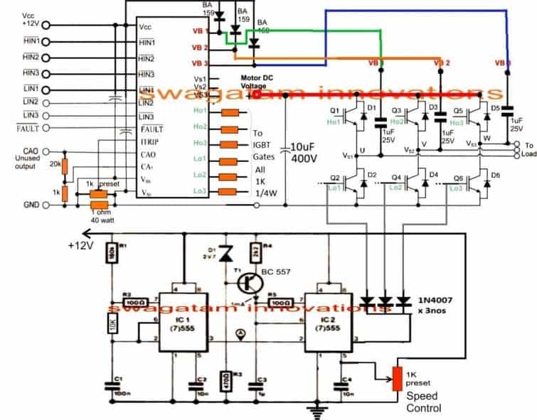

You will have to do according to the following circuit, please ignore the ripple circuit:
There’s another interesting way to vary the output of the IGBT.
You can do it by varying the PWM on pin6 of IC4035, meaning by varying the PWM output of the 555 IC in the following circuit:
Your DC bus circuit is OK, but please add a 100 watt in series initially so that if anything is wrong then the IGBTs will not burn. If the IGBTs are working fine then the 100 watt bulb must remain switch OFF, if it’s glowing brightly that means something’s wrong.
Hi Sir,
I built the IC 555 ckt with 1k pot and tested separately so plz check attached video ( increasing and decreasing pot)
https://drive.google.com/file/d/13ELmUbayV5csKZQfpsHfXDq79oyCCoM5/view?usp=drivesdk
Please let me suggest Is it ok or any changes will be required?
Hi Sanika,
That looks perfect to me. So your 555 PWM controller is also working perfectly. Now you can integrate this PWM with the gates of the low side IGBTs.
When you alter the 555 PWM, the output voltage from the IGBTs must also change proportionately from minimum to maximum.
Hi Sir
It’s my mistake.
I checked all circuit thoroughly and I found Pin No.23 solder issue.i was corrected it and above mentioned problem was solved.
I got below frequency wave form them plz check.
From HO1
https://drive.google.com/file/d/11NLExlFRmGWJcND1rM3wQiTeku1aOhYr/view?usp=drivesdk
From Ho2
https://drive.google.com/file/d/11Ue3_WCV4NWN8Zm1y_XbPbEam19mL2Sf/view?usp=drivesdk
From Ho3
https://drive.google.com/file/d/11Pgn3f4OSt_w6thLiFPfLOlEh2CBnm-n/view?usp=drivesdk
IGBT not getting hot
Sorry.
Hi Sanika, But are these waveform 120 degrees apart, that’s the thing we want to check….all the 3 phase signal must be shown together on the oscilloscope.
Please see how the waveform is shown in the following article:
https://www.homemade-circuits.com/3-phase-signal-generator-using/
Hi sir,
I am working on this kind of project with the reference of your valuable articles, and I got a lot of information from it.
I want to assemble the above project and hope you will be support for it.
1. I have a DC power supply of 550 to 600vdc 50amp (Sorry this is very dangerous but I am taking care and will continue to take care of it.)but I can’t understand how to attach filter means which capacitor and inductor attached with the same power supply for 25 amp .plz suggest
2. Can I use IRS2110 (03 nos) instead of IRS2330 ( it is not available)
3. Can I use IGBT FGA25N120 = 12 pc (2 parallel at Hi side and 2 parallel at low side) in with IRS2110 Driver IC? If yes then which resistor should be used with IGBT gate?
4. Diode BA159 also not available so can I use FR607 (FAST RECOVERY DIODE) instead of BA159?
First I will make PWM VOLTAGE CONTROLLER and should be check it’s output after that I will move on next stage (i.e.03 Phase Signal Generator, then driver circuit)
Before that I want to clear all daubt which is faced during understanding the whole circuit project.
Sir please I am waiting for your suggestions and guidance.
Thanking you
Regards
Avdhoot
Hi Avdhoot,
I appreciate your interest in this project, and I wish you are able to complete it.
However, please note that the above circuit was designed by me with my own understanding about the concept, I have not yet tested the circuit practically.
So the problem is, if you happen to get stuck somewhere while building the project then I will not be able to solve it for you because that would need a practical checking of your circuit.
For the questions you have asked, here are the answers:
1) I would strictly recommened not to use a high current power supply initially, instead use a 310V DC created by attaching two transformers back to back and then rectifying/filtering the AC. Only a 100uF/500V capacitor would be enough for the filtration.
2) Yes, 3 nos of IRS2110 will also work.
3) You can use FGA25N120, but not 12 pcs, rather only 6 pcs, use single devices only, not in parallel. If your circuit works perfectly then you can go for parallel connections, but for the initial basic setup use only single IGBTs.
4) FR107 should also work according to me.
Yes, you must go step wise. Build the 3 phase generator first.
Then make the 555 PWM generator and finally build the 3 phase inverter circuit.
Test and confirm them separately, if all work perfectly, then go for the integration.
Hi sir
I I have received CD4033 instead of CD4035 from online shop. I ordered CD4035 but dispatched CD4033 I Contacted but the same is not available.
Other all components received to me so plz advice me what can I do for the same? It is possible to use it instead of CD4035?
Thanking you
Hi, advhoot
I also using ir2110, i use 10ohm series with the igbt gate. Add around 1k between gate to drain to save u some $$ from burned igbt.
Thanks
I have a IR2130 for the same use. What is about 1 ohm 40 watt resistor? It is not available at my location.
Oh, if you do experiment with lower voltage like from 24-32v transformer, you could scale down your parts. Like using fan motor(connect one to any phase mosfet output and your psu ground), 50v capacitor, 5 watt resistor onstead of 40watt, and cheaper mosfet. Resistor did not to be at exact value, just get as close you could find. For mosfet you could use irf540, xxnyy series(xx is ampere, yy is voltage/10; 30n60 is 30amp/600v max) in to-220 pack which is around 20% the price of an igbt. You only need min of 10amp and 200v max rating. A set of 30n60 mosfet do not even need heatsink for just 1-3min testing.
Ir2130 is quite similar to 3x ir2110 i use, it has 3ch independent half bride. Except it has dead time adjustment, overvoltage protection and work with 2.5v logic. I just build fan78932, which is similar to ir2136 as it only take single pwm input and output 3 pwm shifted at 120° each. It has overcurrent protection too. You could parallel/series 5watt resistor which i think you could find. 10x 0.1r in series or 10x 10ohm parallel 5 watt resistor equal to 1ohm 50watt. Download any electronic calc app, you ll find it handy. Btw, if you didn’t know how to parallel/series resistor i think you should stay away from main voltage, or try your circuit with step down transformer first. I, just like many electronics hobbyist, start from class ab amplifier to learn the basic. Be careful with what you are doing.
Hi Avdhoot, IC 4035 and IC 4033 are two completely different ICs with different pinouts and functions, so they cannot be interchanged with each other.
Hi Sir,
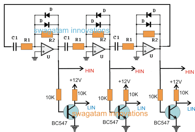
Can I use this circuit design instead of CD4035 circuit
Plz suggest
It is already I made earlier and tested seperately.
Thanks and regards
Avdhoot
Hi Avdhoot, that circuit is good but I haven’t tested it using an oscilloscope. If you have confirmed its 3 phase signal output using an oscilloscope, then definitely you can use it instead of the 4035 circuit.
Good morning Sir,
Just I gave 12VDC supply to ckt and checked output of HIN and LIN at CD4049 section. It is as mention below.
HIN 1# 12V
LIN 1# 0 V
HIN 2# 12V
LIN 2# 0V
HIN 3# 0V
LIN 3# 12V
Hi Avdhoot,
Before connecting you must check the 3 phase waveform from the 4035 IC using an oscilloscope. If you are getting 120 degrees apart 3 phase signal waves only then you can proceed to connect it with the 3 phase inverter IC.
Hello Sir,
Please guide me for below points
1) A homemade V to F converter LED Anode (1k Resistor) and Cathode point where to connect ?
2) What is about Rotor Speed Frequency (Base point of T1 BC547) which point required to be connect?

I am little bit confused so…
Regards
Avdhoot
Hello Avdhoot,
Did you try the first two schematics? I can only recommend the first concepts as I have more confidence on them. The remaining concepts are based on my assumptions only, so I cannot recommend them.
Dear Sir,
Good Morning
I got CD4035 and i started to built ckt. Almost CD4035, CD4009 and CD4049 section is competed. Plz let me guide about CD4009 VDD pin connection. Is it connect to GND? And what is about remained pin of the same? Is it kept free or connected to GND also?
How to check 3 phase generator ckt?
Regards
Avdhoot
Good Morning Avdhoot,
according to the datasheet, the pin16 of 4009 is VDD (+) and pin8 is VSS (-). The inputs of the unused gates are connected to ground, and the outputs are kept open.
Sir can it possible to use 3.3v zener 1/2 watt or 1 watt instead of 2v7 zener diode.
Hi Avdhoot, yes 3.3V zener will also work instead of 2.7 V zener
Thank you sir for your quick response.
Ok sir I can do as per your instructions.
1.This means I only need to use a 310vdc power supply.
2.How many ohm and watts resistor (1ohm,10ohm,100ohm) should be connected to IGBT gate.
Thanking you.
Regards
Avdhoot
Sure, no problem!
Yes, test the circuit with 310V DC acquired from two small back to back connected transformers:
You can add 100 ohm resistors to the IGBT gates.
first of all i have to say something that i am new to this project but i have to make it because it is important to me, i am still stuck on the IGBTs family number that what type of number have to select i requested to all who are on this project. if anyone interested join me on WhatsApp 00923052300002
Hello sir can I use drv8305 ic from Texas instruments as the gate driver
Vinmu, DRV8305 is a full fledged 3 phase motor driver IC….and it can used to drive 3 phase motors.
You can refer to the datasheet of the IC for all the details:
https://www.ti.com/lit/ds/symlink/drv8305.pdf?ts=1680508971625&ref_url=https%253A%252F%252Fwww.ti.com%252Fproduct%252FDRV8305