The simple gate open and close controller circuit is designed to operate the gate through a couple of push buttons manually, it can be also modified for implementing the activation through a remote control.
How it Works
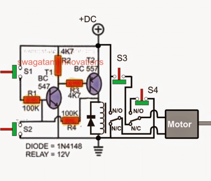
Referring to the shown, simple gate open, close controller circuit below, we can witness a rather straightforward configuration, essentially comprising of a transistor latch stage, a DPDT relay stage and a few push to ON/OFF switches.
The push switches S3/S4 play an important role in the circuit and ensure that the motor never gets overloaded when it reaches its end limits.
The images of the switches which are ideally suited to this application is shown just below the circuit diagram. These are quite popular and can be easily procured from any relevant electronic retailer.
Circuit Diagram
Parts List
- Resistors are all 1/4 watt 5%
- R1, R4 = 100k
- R2, R3 = 4.7k or 10k both
- Relay diode = 1N4007
- T1 = Transistor BC547
- T2 = Transistor BC557
- Relay = 12V DPDT
- S1, S2 = Push button switches
- S3, S4 = push to OFF as shown below
Set Reset Push Switches
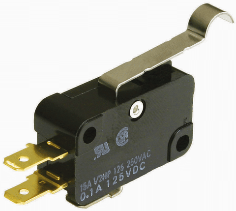
The above Switch is to be used for S3, S4
Transistor T1, T2 along with the associated parts form a reliable latch circuit, S1 and S2 are ordinary push-to-ON switches, where S1 is rigged as the "set" button, and S2 as the reset button, which work for opening and closing the connected respectively.
S3 and S4 are fixed across the end travel points of the gate mechanism, such that the gate pushes these OFF each time it reaches the end destinations, and releases while it moves away from the destination or while the gate is in the course of its travel.
Assuming the gate to be in the closed position initially, we can expect the following scenario:
Operational Steps
S3 in depressed position by the gate and therefore in the cut-off mode.
S4 in released position and therefore contacts closed and switched ON.
The latch circuit switched OFF, and so is the DPDT relay.
The DPDT relay contacts are at the N/C points.
With the above situation, pressing S1 initiates the following course of actions:
T1 and T2 instantly latches, actuating the DPDT relay in the N/O positions.
The motor now begins running through the supply via the S4 and the DPDT relay N/O contact supply in the set direction, enabling the gate to operate with an opening action. This also releases S3 in the process.
As soon as the gate reaches the end limit or the end destination, and opening up fully, it presses S4 cutting off the supply to the motor. The gate now halts and comes to a stand still.
How Motor Rotation is Flipped
This position can be maintained infinitely, until S2 is pressed, which breaks the T1/T2 latch, and deactivates the DPDT relay forcing its contacts to move across the N/C points.
This immediately flips the motor polarity causing the motor to rotate in the opposite direction and enables the gate to reverse back to its closing position. While in this mode the motor gets its power from S3, but only until it reaches its earlier destination, ie. in the closed position, when it presses S3, cutting off power to the motor and yet again disabling the motor.
The gate maintains this position until S1 is pressed yet again for initiating the opening action of the gate...thus the open/close operation of the gate is simply implemented by actuating S1 and S2 switches manually.
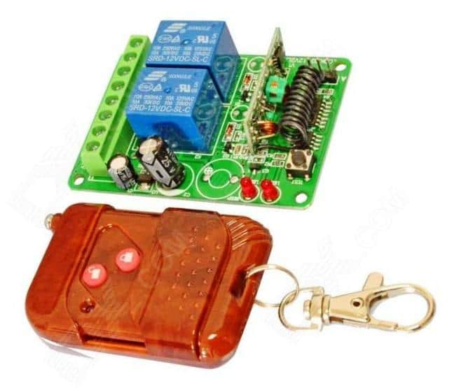
In order to execute a remote controlled open, close action of the gate, S1 and S2 could be replaced with momentary relay contacts, and the relays operated through the receiver unit of the remote control.
Any standard 400 MHz RF, 2-relay type remote control modules could be used for the stated remote open, close control of the gate.

Questions & Answers
Hello Friend
My name is Sotris from Athens Greee, with more than 40 years on the telecommunication field, please if you know suggest to me a company who
produce electronic boards for sliding gates with very low price, 220Vac, slow stop,
terminal sw. normal close, photo, start input,on 433.92 MHZ -110 dbm or better. I want to suggest this company for orders. Thank you
Hello Sotiris, sorry, I have no idea which company specializes in this field, and might help you get the job done.
Did you Google it? I think you can find some good options if you search it thoroughly on Google or maybe use an AI to do the searching for you…
Hi how do you modify the above circuit to be controlled by a remote, kindly avail me with circuit
Hi, I have already answered this same question in the comment to one of the commenters Mr. Ghulam, you can check it.
Good day,
I want to control a swing gate with a motor.
I need to figure out what type of motor and size.
Then I need the control unit with a (car) remote and proximity sensor.
Could you please direct me to the right reading materials?
Thank you much,
Tim
Hi,
Please provide the complete details regarding the mechanical operation specifications of the gate, I will design the required circuit for you.
Regarding the size of the motor, that will depend on the size and weight of the gate.
Please let me know…
Hi Mr. Swagatam, i had question, how if in the middle of moving gate, accidentally one of the other Switch (S1 or S2) pressed, so the S3 & S4 is in the same state (float or N.C Switch), what we must to do?
Hi Hada,
When the gate is in the middle of its travel, both S3 and S4 are in the closed state, that means, if any of the opposite switch is pressed (S1 or S2) the gate will start moving in the corresponding opposite direction….
hello sir, sir can you provide me this same circut with rf module like remote control plz
Hi Ghulam, you just have to buy the following remote control, and replace the S1, S2 switches with the relay contacts of the remote receiver.
ok sir i will purchase by online, and update you, sir how to work this limit switch, and how its connected with the circut or moter? plz guide
Sure, no problem, please buy it and let me know.
The limit switches are push-to-off type, that means in normal condition the switches are ON and will pass current through it, but when pushed, they will turn OFF.
They are supposed to be wired in series with DPT relay contacts as shown in the diagram.
They must be positioned at the end of the curtain travel, so that when the curtain is fully open or fully closed, the relevant S3, or S4 are depressed.
i got it about limit switch thanks, sir i checked price of this 2 chanel module price, its costly in my area, ii have rf module and ht12d and e ics, is it possible can we make ourself? if possible then plz provide me diagram
Ghulam, I would recommend buying the unit from any online store, because making it yourself can be difficult.
However, if you still want to make it, you can try the following article:
https://www.homemade-circuits.com/simple-100-meter-rf-module-remote/
Do anyone have a gerber file for this circuit
Should the green bar in switch S3 be above the contacts?
Thanks, Ralf
No, it is correctly shown below the contacts which indicates that the switch is a Push-to-OFF type switch and not a Push-to-On type like the others.
I purchased one Mighty Mule MM560 automatic gate opener on 06/2017. The board circuit is not working now. So, I purchased one ” 12V DC Wireless Motor Control Switch with 433MHz Keychain Remote with Forward, Reverse and Stop button”. But when the gate comes to the closed position the motor is not stopping. The same is happening at the time of opening. when the gate is fully open, the motor is running. Resulting burned motor. So, what can I add to the circuit so that at the dead end of the gate the motor will stop automatically?
Thank you for your kind reply.
You will need to add set/reset switches S3, S4 exactly as explained in the above article. This is perhaps the easiest way to add the limit switches to the gate open/close actions.
Hello Swagatam,
Currently we have a two wing gate where one wing (left) can be remotely opened (button A) and closed (button B) or both wings operated with button B. I’m trying to make the second wing (right) close (without having to close both wings). The controller is from the Italian company Nice. Installers have now idea how to establish this. Do you?
Hello Tol,
Without seeing the existing circuit/switch configuration it can be very difficult to understand and modify the design.
I have a few questions about gate openers. I have 4 different gates that I have been given the task to take care of. The first is a dual swing gate that does not use limit switches on the motors. It uses resistance to stop the motors at a preset position. The problem with this set up is in heavy winds the gates will start to open then they stop and close because of the resistance. I call the manufacturer and asked if there was anything I could do to keep this from happening and they said no.
How are the resistances used to stop the motors? Is it through the voltage developed across the resistors due to high current on the motor at the preset points?
I can’t figure out how the heavy winds can affect the resistances and disturb the motor operations?
I am not sure exactly how this system works. The other gates I maintain here all have switches on the motor unit that are adjusted to set the open and closed positions.
This system I had to mount a block in the driveway to stop the gate in it’s closed position. When the gates hit this block it stops the gates and the circuit board senses the extra load and shuts off power to the motor. It does the same when the gates are at their open position. There is a stop for each gate in that position.
I am a motorcycle technician by trade and have a broad knowledge and understanding of DC electrical systems. But I lack knowledge when it vome to electronics.
OK, so the sensors are sensing the overload or high current on the motors and shutting off power to the motors. Since there’s no locking arrangement on the gate, it can be difficult to prevent them from opening and closing due to heavy winds.
Hey, i just saw this great article, but I have a question, i have 2 motors but they work at 220v, how can i make this circuit to work with it?
I understand that i can put another DPDT relay in parallel to make both of them working, but this circuit is for 220v, i need DPDT relays that are working at 220v or ?
Thank you!
Hi, you are right, you just have to use another DPDT switch in parallel. For 220V operation, you can simply disconnect the DC connections of the relay contacts and hook them up with your 220V source. Any 10 amp DPDT switch should work for your specific need.
you push to open the contacts thanks
Iam tired of replacing gate openers 400 a shot
yes, push to OFF or break the circuit. Pushing is done by the gate when the end limits are reached.
Hi is S3 and S4 normally closed or normally open
thanks Gary
They are normally closed (push to OFF)
Dear Shri Swagatham
Wil you please send me a circuit for the dor open and close automatically on fixed time schedule by incorporating digital timer in the circuit please send me logic and cetailed electrical circuit to install
Regards
Ramani
Hello Ramani, is it a single door or double door? I can design for a single door only.
Hi Swagath, thanks for the simple super idea. The circuit description is easy to all ages
Thank you Selvaraj, glad you liked the post!
Nice Circuit design swagatam;
i have a gate that has 2 motors, would there be another easy way to add dual logic to this latch circuit?
other than that , i can build two of these and use a remote with 4 buttons for operating ?
just weighing my options to avoid purchasing another gate control since lightning destroyed my circuit board the other day.
thanks for any info you may have ..
Thank you Ian, If you want to control two separate motors using separate switches, then you may have to employ two such identical modules.
On the other hand if you want to control two motors with the same pair of switches then you can use the same circuit, and simply connect another DPDT relay in parallel to the existing relay, and use separate limit switches replicating S3, and S4.
thank you for your time & this is a wonderful resource.. Keep up the good knowledge..
My pleasure!