In this article I have explained the pinout functions of the IC SG3525 which is a regulating pulse width modulator IC. So I have explained in details:
Main Technical Features
The main features of the IC SG3525 may be understood with the following points:
- Operating voltage = 8 to 35V
- Error amp reference voltage internally regulated to 5.1V
- Oscillator frequency is variable through an external resistor within the range of 100Hz to 500 kHz.
- Facilitates a separate oscillator sync pinout.
- Dead time control is also variable as per intended specs.
- Has an internal soft start feature
- Shut down facility features a pulse by pulse shutdown enhancement.
- Input under voltage shut down feature also is included.
- PWM pulses are controlled through latching for inhibiting multiple pulse outputs or generation.
- Output supports a dual totem pole driver configuration.
Pinout Diagram of the IC
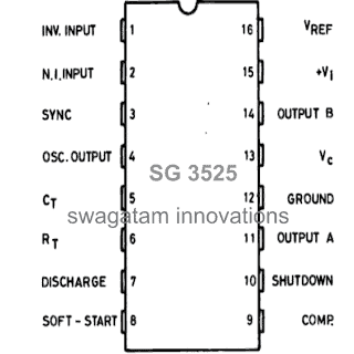
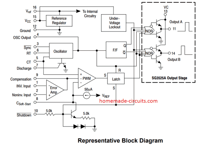
SG3525 PinOut Description
A practical implementation of the following pinout data may be understood through this inverter circuit
The IC SG3525 is a single package multi function PWM generator IC, the main operations of the respective pin outs are explained with the following points:
Pin#1 and #2 (EA inputs): These are inputs of the built-in error amplifier of the IC. Pin#1 is the inverting input while pin#2 is the complementary non-inverting input.
It's a simple op amp arrangement inside the IC which controls the PWM of the IC outputs at Pin#11 and Pin#14. Thus these EA pins 1 and 2 can be effectively configured for implementing an automatic the output voltage correction of a converter.
It is usually done by applying a feedback voltage from the output through a voltage divider network to the non-inverting input of the op amp (pin#1).
The feedback voltage should be adjusted to be just below the internal reference voltage value (5.1 V) when the output is normal.
Now, if the output voltage tends to increase above this set limit, the feedback voltage would also increase proportionately and at some point exceed the reference limit. This will prompt the IC to take necessary corrective measures by adjusting the output PWM, so that the voltage is restricted to the normal level.
Pin#3 (Sync): This pinout can be used for synchronizing the IC with an external oscillator frequency. This is generally done when more than a single IC is used and requires to be controlled with a common oscillator frequency.
Pin#4 (Osc. Out): It's the oscillator output of the IC, the frequency of the IC may be confirmed at this pin out.
Pin#5 and #6 (Ct, Rt): These are termed CT, RT respectively. Basically these pinouts are connected with an external resistor and a capacitor for setting up the frequency of the inbuilt oscillator stage or circuit. Ct must be attached with a calculated capacitor while the Rt pin with a resistor for optimizing the frequency of the IC.
The formula for calculating the frequency of IC SG3525 with respect to RT and CT is given below:
f = 1 / Ct(0.7RT + 3RD)
- Where, f = Frequency (in Hertz)
- CT = Timing Capacitor at pin#5 (in Farads)
- RT = Timing Resistor at pin#6 (in Ohms)
- RD = Deadtime resistor connected between pin#5 and pin#7 (in Ohms)
Pin#7 (discharge): This pinout can be used for determining the deadtime of the IC, meaning the time gap between the switching of the two outputs of the IC (A and B). A resistor connected across this pin#7 and pin#5 fixes the dead time of the IC.
Pin#8 (Soft Start): This pinout as the name suggests is used for initiating the operations of the IC softly instead of a sudden or an abrupt start. The capacitor connected across this pin and ground decides the level of soft initialization of the output of the IC.
Pin#9 (Compensation): This pinout is for compensating the error amplifier op amp. Mostly this pinout is connected to ground via a RC network. However, if required this pinout can be configured with an external transistor which can ground this pin during a critical situation, enabling a shutdown of the IC output.
Why Compensation Network is Required at pin#9
See, if you connect feedback directly without compensation then things do not stay calm, they start misbehaving.
The system can oscillate, like it keeps shaking instead of settling. Output voltage can go up and down.
If load changes then it may become unstable, especially under sudden load change and then you may see strange behavior.
We therefore do not leave it just open..
So we connect a resistor. We also connect a capacitor. Sometimes an RC network between Pin#9 and ground, but sometimes also to feedback pin, depends on how it is arranged.
This then forms what we call a compensation network for the SG3525 IC.
Pin#10 (Shutdown): As the name suggest this pinout may be used for shutting down the outputs of the IC in an event of a circuit malfunction or some drastic conditions.
A logic high at this pin out will instantly narrow down the PWM pulses to the maximum possible level making the output device's current go down to minimal levels.
However if the logic high persists for longer period of time, the IC prompts the slow start capacitor to discharge, initiating a slow turn ON and release. This pinout should not be kept unconnected for avoiding stray signal pick ups.
Pin#11 and #14 (output A and output B): These are the two outputs of the IC which operate in a totem pole configuration or simply in a flip flop or push pull manner.
External devices which are intended for controlling the converter transformers are integrated with these pinouts for implementing the final operations.
Pin#12 (ground): It's the ground pin of the IV or the Vss.
Pin#13 (Vcc): The output to A and B are switched via the supply applied to pin#13. This is normally done via a resistor connected to the main DC supply. Thus this resistor decides the magnitude of trigger current to the output devices.
Pin#15 (Vi): It's the Vcc of the IC, that is the supply input pin.
Pin#16: The internal 5.1V reference is terminated through this pinout and can be used for external reference purposes. Example, you can use this 5.1V for setting up a fixed reference for a low battery cut-off op amp circuit, etc. If it's not used then this pin must be grounded with a low value capacitor.



Questions & Answers
Hello Swagatam
As I have understood, in (at least some) ATX power supplies that use SG3525, TL494 and their equivalents, there is a “feedback weighting network” that is connected to Pin 1. This network is a voltage divider. On one side of the divider, some resistors connect Pin 1 to +5 rail, and +12 rail; on the other side, some resistor connect Pin 1 to GND.
As I also understood, the value of the resistor(s) connected to +5, and the value of the resistor(s) connected to +12, are chosen according to how much importance/weight is given to each in expense of the other; more specifically, if we want +5 not to sag under (heavy) load, we must choose a lower resistor for it compared to the resistor we choose for +12, and this inevitably causes +12 to sag under (heavy) load, and on the other hand if we want +12 not to sag under (heavy) load, we must choose a lower resistor for it compared to the resistor we choose for +5, and this inevitably causes +5 to sag under (heavy) load.
Is my understanding correct? If not, can you correct my understanding?
Hi SA,
Yes, your understanding is basically correct. Pin 1 is sensing a weighted combination of +5V and +12V through the resistor network, not sensing both rails independently.
So if you use lower resistor value for +5V, then +5V gets more weight and controller will try to keep +5V more stable, while +12V can vary more. If you give more weight to +12V, then +12V will be controlled better and +5V can vary more.
But the final sag also depends on transformer winding ratio, winding resistance, rectifier drop, load and cross regulation. So it is better to say the feedback network gives more priority to one rail, not that one rail will always inevitably sag.
Of course; the priority that feedback weighting network gives to one rail in expense of the other is only one possible cause of voltage sag in that other rail. There are other possible causes of voltage sag including the ones that you mentioned.
My other question is about SG6105(DZ) IC. This PWM IC seems to have been designed by System General Co, like SG3525 IC you talk about in this page. But SG6105(DZ) is 20-pin, unlike SG3525 which is 16-pin. There are other differences too. For example Pin 1 of SG6105(DZ) is PSON, whereas Pin 1 of SG3525 is INV.INPUT.
Can you please take a look at version 1.0.1 (25-9-2007) datasheet, and version 2.3 (19-6-2003) datasheet, of SG6105 at the links below:
https://www.datasheetarchive.com/datasheet/SG6105ADZ/Fairchild-Semiconductor?term=sg6105&version=1
https://www.alldatasheet.com/datasheet-pdf/view/90301/ETC/SG6105DZ.html
Question:
Which pin in SG6105 is equivalent to pin 1 in SG3525, that is, which pin in SG6105 must the resistors of feedback weighting network be connected to? Why?
Actually I think, SG6105 is quite different from SG3525, so you cannot compare the pin numbers directly.
As per my observation, for the feedback weighting network of +5V and +12V, the equivalent of SG3525 Pin 1 is SG6105 Pin 17, marked as IN. This pin is the input of the internal error amplifier so the feedback resistors from +5V and +12V are connected to this point.
So simply, for the main +5V/+12V feedback loop: SG3525 Pin 1 = SG6105 Pin 17 (IN), function-wise.
Thank you for putting this information out. I was reading the comments and you have the patience of a saint. Everyone asking you to design some idea they have without doing any reading and research. I would’ve shut down comments long ago. Most of it you can’t even understand…….
Thanks for your time in helping others.
Thanks for your honest feedback, sometimes I do find it difficult to handle some of these comments but still I make sure to answer them because I believe that’s what makes my blog unique compared to other online websites..
Pin 8 ter ukur 0 volt. Bagian mana yng bermasalah?
Why do you ant to measure pin#8 voltage? It is for applying soft start only. Is your inverter working normally?
Tidak. Inverter saya bermasalah frekwensi out tidak keluar. Pin 8 soft star 0 volt. Dimana letak masalahnya?
If your inverter is not working, it may be due to some other reasons, pin#8 is not where it needs to be diagnosed. You can just leave the pin#8 connected to ground through a 1uF capacitor, and check other points like Rt/Ct pins, check whether you are getting a frequency across the Ct capacitor or not…
Jadi yang menyebabkan pin 8 soft start 0 volt apa? Seharusnya ada tegangan 4,7 volt di pin 8.
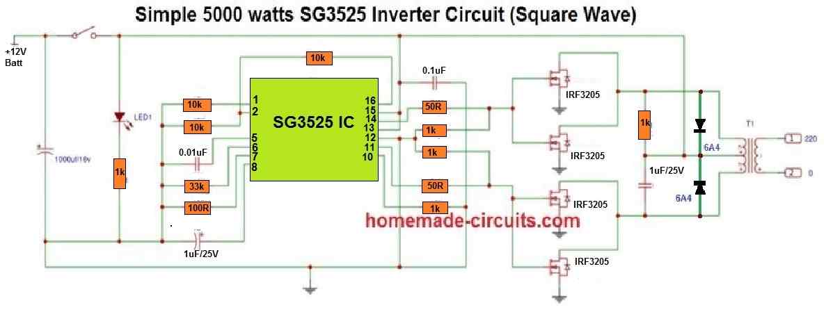
Are you getting a frequency at the output pins of the IC, or across the pin#5 capacitor? If not, then your IC may be faulty. Please build it in the following way and check again:
please apart from pin 11 and 14, how can I generate pwm output from another pin if I want a single output.
You can try the following configuration:
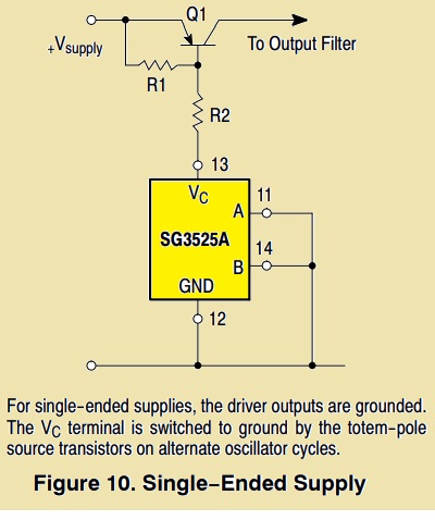
Thanks for this. please recommended values? I don’t understand “to output filter”?
Please ignore the “filter” word….you can use the output as the ON/OFF single ended oscillator.
Yes sir, thanks, please value for R1, please how can I use npn transistor instead of PNP?
Both the resistors can be 10k, and the transistor can be BC557…
hello sir
whit thankfully for useful explanation
I have a MMA inverter welder use sg3525 card control and I turned it for TIG welder and I need to shot down while weldering for this option i used a key for connecting pin 10 to 16 after a few times TIG weldering the Igbt went to die (😂)so pls tell me why and if help me to understand how I should
thank you
shahab
podes probar las mediciones del IC 3525 16 pines porque tengo uno y no se si mide bien los pines gracias
Hello Shahab,
Connecting pin#10 to pin#16 or the positive supply should shut down the IC output, so that should not cause the IGBTs to burn, but maybe due to the sudden voltage spikes the IGBTs are getting affected.
Make sure to use resistor across gate/emitter of the IGBTs, connect reverse diodes across the collector/emitter of the IGBTs, and consider using an IGBT rated to handle 2X power than the load power.
UC3525 Half bridge converter output voltage increases 2V, to 3V from set voltage
sir please can you help me out with the formula solving
sir i want laminating transformer full data.
You can refer to the following article:
https://www.homemade-circuits.com/how-to-make-transformers/
swagatam sir i want 7amp18vdc to 14vdc regulating power supply for lead acid battery charging
You can try any LM338 based power supply. Use two LM338 in parallel.
ckt diagram pls sir
Please refer to the LM317 based circuit, replace the LM317 with LM196 or use two LM338 in parallel:
https://www.homemade-circuits.com/how-to-make-current-controlled-12-volt/
hai sir i have one drought ,sir can run 24v operating voltage inverter transformer, to 12v.
sreenivasulu, I cannot understand your question.
24v operating inverter , can run 12v operating supply, in case 24v inverter secondary side winding modification , i mean 12 0 12v,
24V inverter cannot run on a 12V battery, for modification, rewind the DC side winding to 9-0-9V
it will runs 12v sir
I have tried this IC synchronization many times but the output results remain unstable
if you run a 24V transformer with 12V then the output will be 50% lower.
swagtam sir if 1000w inverter trasnsformer priymariside turns reduced i mean 230v turns data ,reduced 60v will increase amps. can i give e bike operating voltage 60v, 18amp.
Yes it will increase the amps proportionately.
swagatam sir how can convert 200w , to 500w inverter ckt board.
sir pls say high amp mosfet number and transformer rating that means amps rating, can i use same ckt board
sreenivasulu, please tell me the power (watts) of the inverter that you want to build and which circuit diagram?
i have 10v 0v 10v transformer 18amp . it can useful sir,further upgrading 5oow .convertion.
i am purchased amazon 200w kit irf 44n, pulsmodular ic sg3524 using ,for amlification boosting bc547 npn used thats kit.
First try the board and check whether you get 200 watt power output or not….if the boards works correctly, then you can upgrade the MOSFETs by replacing them with IRF3205 (3 in parallel). The battery must be also upgraded to 200 Ah….
18 amp transformer will produce only 10 x 18 = 180 watts….so it will not work for a 1000 watt output
can runs atx transformer, 3 atx transformers , 3 nos 200w boards,and individual for 100ah 12v battery.
If you want to use ferrite transformers then its winding will need to be calculated.
sir can i use 200amp inverter welding machine ferrite core transformer.
Without calculating the winding and matching the circuit frequency you cannot use any ferrite transformer.
winding cliculation formula need sir, can generate 70v,12 amp with help of ferrite core transformer. then connect 3sets connect o/p voltages in parllel 70v,36amp.can get using e bike operating voltage .
You can refer the following article, but i cannot help with the calculations, you will have to do it yourself:
https://www.homemade-circuits.com/how-to-design-and-calculate-ferrite-core-transformers-for-inverters/
which amp rating transformer suitable sir
For 1000 watt inverter, divide 1000 by the battery voltage that will give you amp rating of the transformer.
You can do it by upgrading the mosfets, battery and the transformer.
swagatam sir sg3524 and sg3525 both are same or not,
Yes, both are same with their basic functions, but please refer to their datasheets to confirm the pinouts
What is Maximum output current of sg3525.can I drive directly irfp250 MOSFET.
You can drive the MOSFETs directly from the SG3525 outputs, MOSFET gates do not require high current to operate.
Hi swagatam
Please sir which this, is the real formula “1/CT(0.7RT+3RD)” or “(1/CT(0.7RT+3RD))(0.5)” in calculating the frequency in this IC SG3525
Hi Emmanuel,
The formula is
f = 1 / Ct(0.7Rt + 3RD)
The PWM frequency relies on the timing capacitance and resistance, with the timing capacitor (CT) linked to ground through pin 5 and the timing resistor (RT) connected to ground through pin 6. Additionally, the deadtime is determined by the resistance between pins 5 and 7 (RD) and to a lesser extent, this value also affects the frequency.
i know all those connections but I’m confused with the formula because I find out that the IC can only oscillate from 100Hz to 100KHz and if needed for 50Hz on the output of a transformer one need to calculate for 100Hz and multiply it with 0.5 which is 50%. So I need clarification on this please.
Yes, what you have learned is correct, but since the IC can oscillate at a minimum 100 Hz, it cannot go down to 50 Hz. You will have to use a divide by two stage for getting 50 Hz.
Thanks for your quick response.
I would have like to see your prototype for the SPWM chopping aspects of your SG3525 inverter so to see the output waves form of the design.
No problem, If I happen to build a prototype I will surely let you know and show you the waveform.
Thanks you very much and keep up the good work.
You are welcome Emmanuel!
Swagatam,
I am trying to get a smooth control of PWM using the SG3525 especially when using an optocoupler which only has a small adjustment range on its input. Most of the circuits I have tried give me either no output i.e. PWM too narrow or normal output i.e. no PWM control with nothing in between.
What am I doing wrong? Is there a circuit which I could use which allows me experiment with the range of control?
Hello Paul, please explain the schematic that you have used, without understanding the schematic it can be difficult me to suggest.
please someone help me to know more about compensation in sg3525
Hello again, for a push pull transformer would I have to reduce the oscillator frequency in half for transformer calculations?
The oscillator frequencies at pin#11 or pin#14 should be 50 Hz, if 50 Hz is required at the transformer output, or 60 Hz if 60 Hz is required at the transformer output.
Thank you! On the datasheet I do not see suggested values for soft start capacitors or a max/min value. Would 1 pf work?
In some schematics I have seen pin#8 connected directly to ground when not used. I would prefer connecting a small value capacitor instead…yes a pF will work.
Hello, to disable soft start can I leave pin 8 floating?
Thanks,
Jon
Hi, I am not very sure about it, it is better to keep a very small value capacitor connected, such as a 0.001uF or similar.
Hi,
Please i will like to know the pin of sg3525 that is called PWM feed or the pin that two diode in sine wave can be fed to when using sg3525 as PWM oscillator in design a pure sine wave for inverter.
Regards,
Sina.
Hi, according to me there’s no such pinout which can be used to convert the IC SG3525 into a pure sine wave inverter.
I am ANURA SENANAYAKE. From sriLanka. I am a goverment nursing officer. But Iam an electronics hobbiiest. I always follow you. I preferred your articles. Wish you a bright future.
Thank you so much Anura! I appreciate your kind feedback!
Hi swag..
I build an smps inverter using the sg3525
When I power on the upper fet is very hot and the lower fet is cool and without load at the output of transformer. so I swaped the drain pin of the transformer but no changes then I return the connections back at it was then I swaped the gate the upper MOSFET which was at pin 14 that was heating to I swap it to pin 11 then the lower which was cool to from pin 11 to pin 14 then I power it on again so the lower MOSFET which was cool began to hot then the upper MOSFET which was hot before is now cool and if i leave it for long MOSFET get damaged.my ferrite transformer is 3+3 turns primary ,please help me I have Been trying for long but still same issues pls how do I tackle this fault what might be the solution I will be grateful in advance..
Okay I will try it again and give u feedback..
Hi David,
It seems something might not be correct with your ferrite core transformer and that might be causing the asymmetrical switching and heating of the MOSFET.
You can try increasing the turn number to 5+5 and check the response.
Hello,
I tried with pin 10 to use as shutdown for voltage regulation. I use TVS diodes to shut down the IC once a certain voltage has been hit (in this case 390 volts) it works fine however I am wondering how much current I should send to pin 10? I cannot find this anywhere in a datasheet.
Thanks,
Jon
Hi,
As per the internal diagram of the IC, the pin#10 has an integrated 5K series resistor, so this pinout is protected internally. The current is thus immaterial and can be of any value….however the voltage to pin#10 should be restricted below 12V.
Hi Swagatam, for operating a parallel resonant hi Q resonant inverter single leg I need to adjust the delay time in such a way, so to have a little overlap in opening of MOFSETS 1 and two. If I don’t use dead time resistor between legs 7-5 will I have some overelap in openeing the MOSFETS (shorting them). The circuite is here on page 5 figure 18.2 c : personal.strath.ac.uk/barry.williams/Book/Chapter%2018X.pdf
Thank you in advance
Regards
Emil
Hi Emil, I think SG3525 provides a minimum degree of dead time by default, so even if you don’t connect the dead time resistor across pin#7 and pin#5 still it won’t cause a shorting of the MOSFETs.
Hi Swagatam, thank you for your reply.What if I make a circuit with adjustable duty cycle and use the HI output twice: once directly to MOSFET 1 and second inverted through BC547 to MOSFET 2. Does the inverted signal keep the adjusted duty cycle of 50.01 or the inverted signal will be with duty cycle 49.99 which I don’t like it to be?
Hi Emil, I think the inverted duty cycle will be 49.99.
Hi Swagatam, thank you once agin. Verry kind of you. Meanwhile I solved the problem via a transformer driving the inverter leg trough the secondory. Ot works wonderfully. Thank you once again.
Thank you Emil, Glad you could solve it quickly.
Hie Chief
Have a question regarding pin 9, I have seen some Chinese welding inverters using Sg3525 as pmw control IC. What I only know about duty cycle is I use pin 1 as feedback pin but in these machine they ground pin 1 and use pin 9 to control duty cycle. How is that possible. Please explain .
Hi Francis, yes pin1 can be used as the feedback, since pin1 is the input of the one of the error amplifier. Pin9 can be used with an external PWM to control the output duty cycle.
You can refer to the following posts to learn about these pinouts
https://www.homemade-circuits.com/lm3524-datasheet-pinout-function-how-to-use/
https://www.homemade-circuits.com/inverter-circuit-with-feedback-control/
Dear Sir, would you be kind enough to post a SG3525 Test Circuit ?
(How to test working of SG3525)
Thank you very much in anticipation.
Hello Imsa, you can get the test circuit in the following datasheet of the IC. Please see the Figure.2 in the datasheet.
https://www.onsemi.com/pdf/datasheet/sg3525a-d.pdf
Hello Swagatam
I have built an inverter and its working well except that it is giving me 375ACV at the transformer output instead of 220/240ACV when the DC input voltage to the inverter is between 22 – 25.5VDC.
Could please assist me with a feedback output circuit for controlling 375VAC to 220/240ACV?
Your assistance will be appreciated.
Thanks
Aaron
Hello Aaron, The output voltage depends on the difference between the battery voltage and the transformer primary voltage rating. If the battery voltage is higher that will cause the output to be higher proportionately. You can refer to the following post, the first 3 designs have an automatic output voltage regulator facility
3 High Power SG3525 Pure Sinewave Inverter Circuits
Swagatam, I have a need to place two of the GFZ-11 12VDC to 220VAC modules in series and would like to sync the two modules to produce a 440VAC out by placing the two transformers in series.
The problem is I have tried tying the two sync signals together on pin 3 and that does not work.
As an EE I think but would like to verify that I can use the two PWM outputs on pins 11 and 14 to drive more than one set of FETs.
This would give me two identical FET/Transformer sections an equal drive and resulting output frequency and phase.
I believe this would give me the ability to place the two transformers secondary’s in series to achieve the desired 440VAC output.
Correct me if I am off base with this idea.
Hello Jim, yes definitely you can put two sets of MOSFET/transformer across the output pins of the SG3525 or any similar IC and generate two separate AC sources. In fact this arrangement will ensure perfectly similar and in-phase ACs which can be joined in series with perfect results.
OK, I guess the last comment did not go through.
So here I go again.
I need to vary the output voltage of the circuit, due to this being a PWM system I would think that I could vary the PWM signal, but I do not wan one fet to be on all of the time during a very low percentage PWM output event.
Is there a way to modulate both the push and pull PW to be equal in duration as to not cause a thermal run away event?
Where may I find more application data on this SG3525 device?
You can probably do it by adjusting the dead-time of the IC, through a variable resistor connected between pin#7 and ground.
More related info can be found under these posts:
https://www.homemade-circuits.com/dc-to-dc-converter-circuits-using-sg3524-buck-boost-designs/
https://www.homemade-circuits.com/inverter-circuit-with-feedback-control/
https://www.homemade-circuits.com/lm3524-datasheet-pinout-function-how-to-use/
Good news I just tried the dual series driven by one SG3525 aand they are perfectly synced. Great now to work on varying the output.
that sounds great, thanks for updating!
This is part of a flash capacitor charging circuit and I will need to be able to adjust the charge voltage at the caps.
I have built a comparator which controls the shutdown pin 10 to deactivate the invertor, and it works OK, but I was wondering if there were other more reliable circuits I may use.
I need to control from 30V to 700V DC.
I will be rectifying the series transformers output and charging the flash cap bank through a charge limiting resistor so the charge voltage will be slowed down.
I am measuring directly from the flash cap bank through a series of 2Mohm resistors to ground, tapping a 270Kohm resistor to measure from.
If it’s DC that you are looking for, then I would recommend using separate bridge rectifiers across the outputs of the two transformers, and then connect the +/- from the bridge rectifiers in series for getting the required 700V DC
I appreciate the quick reply, I just wanted a sanity check before I go and blow some units up.
I like blowing things up but not my boards.
Thank you, Glad it helped!
i made a circuit using ir2153 but the fets blows as soon as i switch on power
is it possible to use sg3525 and a push pull transformer but powered by 300Dc not 1 or 48
what will be the primary/secondary voltage specs of the transformer??
Hello Mr
its nice to check the circuits & ideas on this site
i need your help making a pure sinewave inverter
as a suggestion which circuit is the final one of sg3525?
if i want to use Arduino to generate spwm chopping the output of the sg3525 is that possible?
or if i tried your Arduino example how to set the output voltage or the hertz?
thanks for help
Hello, yes that is possible. You can connect the SG3525 output to a push-pull BJT stage through 1K resistors, and configure the BJT buffer output with the power MOSFET stage. After this you can integrate SPWM with the bases of the BJT stage for the required sine wave chopping.
An example concept for the above can be witnessed in the following article:
Convert a Square Wave Inverter into a Sine Wave Inverter
thankls for reply
which sg3525 is the final one because i have noticed a different circuits on this site
different values of resistors & other parts of the circuit
You can use any SG3525 circuit from this website or from any external source….it’s just about configuring the output stage appropriately for the phase chopping
thanks for your reply Mr
its easy to reset the Microcontroller to start the cycle again after using one cycle only
but do i need to Recalculate the delay periods of the code ?
But how to get this from Sg3525 ?
as i see the sync output is an oscillator output i guess
Thanks Mr
So i have to measure the pulse period of Pin 5 & use this time in arduino to generate Atleast 5 spwm blocks or more i guess will be better smoothing the wave right?
I like to use the sg3525 features & use the arduino to generate spwm signal & some extra festures to the inverter
Yes that’s correct, but higher pwm blocks will not be good for iron core transformer.
You can get a triangle wave pulse from pin#5 of SG3525, you can use this pulse to reset the Arduino. The Arduino must preferably generate a minimum 5 block SPWM which must accommodate inside the each resetting time period. So this 5 pillar SPWM must keep recycling in response to each triangle wave pulses from pin#5 of the SG3525.
The sync output can be used to sync the SG3525 through a 50 Hz or 60 Hz pulse from the Arduino, but would be more complex to code and configure.
in the arduino Circuit there is 2 outputs
do i need to use the both outputs to drive the BJT’s?
or like the first circuit use 1 pin to Bases of both BJT’s?
then i need to modify the Arduino code so it can produce varying pwm on one pin
is that right ?
thanks
how to get it triggered from sg3525?
Do i have to modify the delay in Arduino Code or its enough to delete the second half of the code?
Just deleting one half of the code will not be enough. The SPWM cycles mus be synchronized with the SG3525 output switching,for this you will have to modify the code so that it accepts an external signal and resets the code to start from the beginning. In this way the SPWM sets will be delivered to the two BJT channels in a uniform manner.
You will have to use only one output from the Arduino and modify the code so that it generates the varying SPWM with a total delay that corresponds to one cycle of a sine wave. And this SPWM set must keep switching again and again continuously in response to the alternate switching of the SG3525 output. Meaning, after the Arduino completes one SPWM cycle, it must be triggered from SG3525 outputs to reset the Arduino and start a new cycle again.
Welding inverter modified to charge and desulfator battery,why did adjusted output voltage by connected VR10k at pin9 to GND
Just use a D-flip/flop, it divides by 2 by itself ;-?
How I can decrease the output frequency to be 50 hirtz
Hi Swag can i send you the circuit diagram to get your opinion on this subject?
thank you!
Hi Matt, sorry, it can be difficult to diagnose the fault by seeing a diagram. You must first test the standard 3525 configuration and confirm the output oscillations, if it is working then your IC is OK and then you can proceed with the external frequency connection on the specified pinout.
Hi Swag ok for pin 3 but exactly the same result! maybe de ic is over?
Yes that may be possible, is the IC oscillating with the normal set up using Rt Ct, if yes then it is not over yet!
Hi Swag i have tried to connect the ground with the other circuit (common gnd) (the pwm capacitors and resistor mode on pin 5 and 6 is ok 1% to 49.9%) but, when trying to disconnect pin 5 and 6 and connect an external frequency (pin4) i have no pwm! (4,2%)
thank you for your help!
Hi Matt, the synchronizing external clock must be applied to pin#3, not pin#4.
hello swag im trying to connect the 3525 pwm on pin 2 with external signal 0 to 5v! and an external frequency of 50KHZ on pin 4! on pin 11 and 14 i have 50KHZ but no pwm!
Matt, did you connect the ground of the external signal with the ground of the 3525? If you do this then the PWM should definitely work
Hello Swagg on my sg3525 i have connected an output 50KHZ frequency on pin 4 and its ok , and connected a variable 5v on pin 2 for a pwm but theres no results! ive disconnected pin 7 and 6!
have you any idea?
thank you!
Sorry matt, I am unable to understand the configuration, and the reason behind it….
can i send you the schematic by email?
thank you
Please explain the purpose of those connections, so that I can understand your exact requirement.
Hi I have a problem with my welding inverter, it uses the compasetion pin #9 for feedback pin #1 GND,#2 is tied to Vref
Greetings,
Clear-cut explanations about the component. Extremely useful for beginners. Welldone
After replacing this IC I did quick continuity test to ensure that everything is ok. Seems like there is 0 resistance between pins 1 and 12 and between pins 3 and 12 (this also means that pins 1 and 3 have 0 resistance between each other as both have same ground). Is this ok as pin 12 is ground or does it mean that something else is still broken?
Sorry, ICs cannot be checked by measuring resistances across their pins, you must configure them as per their standard design and then check whether it
is providing the expected results ro not.
Swagatam Ji ,
Namskar,????
I have a inverter welding machine.
SG 3525 ic is used to control mosfet.
I can get 20 to 200 amp from this system for welding. There is a potentiometer to adjust amperes from 20 to 200.
But output voltage remains 40 to 50 volt .
I want to modify this Machine so that I can get variable voltage also at output.
Can you please advise me how I should connect another potentiometer and resistance to get variable voltage.
Namaskar Devendra ji, without seeing the circuit diagram it can be difficult for me to give a proper suggestion.
Example/test circuit shows capacitor for pin 9 with value of 0.01 but with no unit. Is this μF, nF, or pF? I managed to physically break this capacitor in my SMPS when I was replacing the IC so I am not able to measure it. and what would happen if replacement capacitor is either 1000 times less or 1000 times more capacitance?
I cannot find any example/test circuit in the above article, please indicate its exact location.
I meant this manual, page 5:
https://www.onsemi.com/pub/Collateral/SG3525A-D.PDF
Also I just now noticed that this article is about SG3525, but this manual is about SG3525A. Are they same or different things?
The 0.01 refers to 0.01uF capacitor. SG3525 and SG3525A are one and the same.
Thank you!
Could you also share how you reached to that conclusion? Is it default to assume that capacitors in IC circuits are in uF? Since I dont have much experience, I would just like to know if you got some hints form somewhere or is it default assumption that if unit is not marked it is uF?
A pF and nF value will always have these units marked clearly, if there’s no designation indicated then yes, it is uF by default.
Hello Sir
I have learnt a lot from your replies.But i would like to know if SG3525 has internal feedback system,and would like to know the formula for calculating then oscillation frequency of the IC ,say 50hz.Results from sites does’t satisfy me.Thanks so much.
Hello Patrick, I have updated the formula for calculating the frequency of the IC output. Please check the RT/CT pinout details above for the details.
The feedback can be added at pin#1 of the IC as indicated in the diagrams in this article:
https://www.homemade-circuits.com/sg3525-pure-sinewave-inverter-circuit/
Hello Mr Swagatam, I used the sg3525 to drive my half bridge mosfet in my half bridge SMP but, I noticed that the low side mosfet gets hot and high side mosfet remains cool or warm. If I leave the circuit running for longer time, the low side mosfet gets hotter. This happens only when a load is connected at the output of the ferrite transformer.
Turns ratio of this main ferrite transformer is 1:2 stepdown configuration. The load on the output consumes as high as 1Amp. I have used an RC snubber connected at the drain to source of the low side mosfet, though the temp. rise decreased and it wasn’t as high as when there was no snubber, but I really need to get rid of this fault.
Please I need your idea on how to stop this problem. I don’t know if this is a problem or just nothing to worry about.
Hello Victory, it can be difficult to judge the fault without checking the functioning in detail. A waveform analysis across the various points can perhaps help to the diagnose the fault better. Alternatively you can modify the MOSFET configuration as per the concept explained in the following article;
SMPS 2 x 50V 350W Circuit for Audio Power Amplifiers
I’m really appreciate your helpful explain of SG3525. So if i’d like to make a lag time between Pin 11 and Pin 14 but the freq and the duty cycle is the same , is it possible ?
My english is not good, hope you understand what i means .
Thank you so much .
Thank you, Yes it is possible to alter the deadtime without effecting the frequency, but the duty cycle will be effected
I put the double 555 circuit together as shown in the diagram that you had sent. Very nice looking waveform up to about 75% duty cycle but then goes unstable when I raise the control voltage further in an effort to go to a higher duty cycle. By the way, my power voltage is about 12.8 volts. Any suggestions for reaching a higher duty cycle? I would like to reach 95% if possible. Also, the operating frequency is about 75 Hz. I would like to operate somewhere in the range of 200 to 400 Hz. Thanks very much for any further help!
To confirm the maximum possible PWM from the IC, you can try connecting pin#5 of IC2 with the positive line of the circuit. This will provide an accurate idea regarding the maximum PWM capacity of the circuit. Beyond this level it may not be possible to increase the PWM%
The resistor R1 and the capacitor C1 together decide the output frequency or the the number of pillars per second of the PWM, so you can try manipulating the values of these 2 components to adjust the output frequency as desired. Hope this helps!
Thanks very much for your prompt reply. Will try your suggestion. Do you have any preferences/recommendations as to types of capacitors (e.g., ceramic, etc.) and resistors to use? I also see that there is an LM555 timer circuit available – would there be any difference from the NE555P IC that I have been using?
The 1uF can be an electrolytic, while remaining can be ceramic types.
Any IC 555 will work, as long as the the working supply voltage is above 5 V, the initial prefix will not make any difference.
I am designing a circuit for a solar PV-thermal system which will use a solid state relay to provide a pulsed current flow (PWM) from a PV array to an electric resistance heating element, in order to hold PV panel voltage at about 30v each, plus to ensure regular zero voltage at heating controls to prevent DC arcing. I have tried using 555 and 3525A integrated circuits, with control voltages derived from PV system voltages, but have experienced poor performance/stability at low duty cycles, which will be important for functionality under low solar insolation conditions. Could you suggest either a 555 or 3525 circuit which would actually work? Or any other approach to go from a 0-10 vdc or 0-30 vdc input to a PWM output? I need to keep the PWM frequency under 500 Hz based on the needs of the solid state relay. Thanks for any help.
you can try the following concept. You can eliminate all the stages which is linked after the pin3 of IC2, and use a MOSFET stage directly with pin3 for integrating the heating system.
Please I need your help Mr Swagatam, I just tested my sg3525, checked everything and found them to be alright, but, my sg3525 warms up quickly even when it’s totem pole drivers have not been used as a driver circuit to drive any mosfet.
Please I want to know if it’s normal with the IC or if I am not doing something right. If it’s normal, can you explain how to manage this thermal issue. Thanks
Victory, what safety measures did you apply at the Vcc pin of the IC? Please follow the following diagram and replicate them for your IC also.
if inductor is not there with you, use a 100 ohm 1 watt resistor
By the way if it is warming up without a transformer/MOSFeT connected, and with 12V DC then definitely your IC is faulty or there’s some fault in your connections.
Pls Mr Swagatam can you help me understand the use of circular mils per amp. This parameter is required when calculations are being made for the wire size needed for transformer design in SMPS. It is used in many textbooks on SMPS that I have come across, but I don’t still understand it’s use as regards current carrying capacity of a conductor. Pls, I need your help. Thanks.
Victory, According to my understanding it is the cross sectional area of the wire which can handle 1 amp current comfortably. It is equal to the square of the cross sectional diameter of the wire and denoted by the formula:
A = d^2
Ok Mr. Swagatam, thanks for the reply.
I don’t have an oscilloscope to see the PWM signals, but isn’t there any table that shows the deadtime length per Rd value? I can’t find any such table from the datasheet.
Hi Victory, I don’t have any info regarding that, but you can physically check the output DC to know the level of duty cycle the resistors are able to vary. Lower dC will mean lower duty cycle and larger dead time and vice versa.
Hello sir
Am beginner, I want to construct 500w inverter using sg3525.
But I need to know, did sg3525 need regulator if it will power by 12v 75AH?
Hi, you can try the 3rd circuit from this article:
https://www.homemade-circuits.com/sg3525-pure-sinewave-inverter-circuit/
Hello Mr. Swagatam, you said that deadtime can be set be placing a resistor between pin 7 and ground, but I read, from some other article on the web, that the deadtime is also set by placing a resistor between pins 5 and 7. Don’t know which to follow as this is confusing. Please, which do I follow?
Also, is there any formula for calculating deadtime length? because I couldn’t find any such formula on the net or even from the sg3525’s datasheet.
Hello Victory, yes there was a mistake in the above article, I have corrected it now. The deadtime is fixed with a resistor between pin5 and pin7. It seems this resistor decides how fast the Ct can be discharged and how thin or wide the output pulse width can be. Thinner PWM would mean higher deadtime and vice versa. So the formula has to be related to RC time constant.
Hi,I’m designing a 5KVA pure sine inverter. I’m using this sg3525 for the pre-stage push pull converter to convert the battery level to 400v. but the feedback op amp is not so accurate. So is it possible to just ignore the IC internal opamp and connect the output of an external control circuit to the compensation pin of sg3525(pin9)?
and what is the maximum voltage that can be applied to pin 9(comp pin)?
and is it logical to share the grounds from both sides of the transformer just to have a feedback for sg3525?since the whole point of a push pull converter is the grounds isolation
Hi, SG3525 feedback system is very accurate if wired correctly, still you can use an external op amp for this. However, it is pin1 or pin10 which is normally used for feedback output control, I am notsure how pin9 can be used for this.
you can check the 3rd diagram from the following article for more info:
https://www.homemade-circuits.com/sg3525-pure-sinewave-inverter-circuit/
Thanks for answering swagatam
I studied the datasheet and tested the IC.I found out that pin 9 is connected to the output of error opamp and the input of pwm generator unit.the voltage on pin 9 varies from 0.2 to about 5.6 volts by changing the feedback and reference voltages. Therefore I applied an external voltage source on pin9 and was able to control the duty cycle accordingly.
For the SPWM part,I’m using EGS002 module, since its super easy to use
OK Alireza, in that case you can apply the external PWM to pin9, the peak voltage should not be more than the supply voltage used for the Vcc of the SG3525 IC
Hello Swag
is it possible to use the voltage correction of sg3525 as variable output for exemple 0-220vdc
by adjusting the error amp input of the ic ?
Hello yassi, yes that’s possible, but with a transformer at the output.
Hi Swag so for pin 10 a should have a pwm frequency! what frequency do i need for pwm input? 50HZ 200HZ?
sorry!
thank you!
Mathieu, If you ae trying to achieve a constant voltage output then PWM is not recommended, instead you can use a resistive divider network at pin#1, as done in the following design
Hello Swag: sorry but isn t a dc voltage on that pin?
Hello Mathieu, a DC at pin10 will permanently shut off the iC, do you wish to have a permanent shut off?
Hi Swag ive finished my voltage follower! can i fix it on the pin 10 of the SG3525 for a pwm?
thanks reguards
Hi Mathieu, if you have confirmed the response with a scope then you can try it with pin 10 of the of SG
Hi Swag for a pwm on pin 10 what maximum voltage does this pin can support? can this pin work for a better pwm?
thanks!
Hi Mathieu, it can support upto the supply level of the IC
Hi Swag for pin 10 you told me that pin 3 of the second 555 will be connected on pin 10 of the SG3525 sorry but its a PWM is that?
yes PWM is not an AC, and frequency is not relevant to pin10, because it responds to only for high or low signals. Wider PwM will make the shut down to last longer, and vice versa, thus controlling the output average voltage. You can also use the 555 PWM with the dead time control pin7 of the IC with similar results.
(connect it with pin10 of the IC)! so pin 10 is a dc voltage but on the (output voltage correction of a converter).post you insert the 555 pin 3 pwm! i dont undersand so well
thank you sorry !
Hi Swag what is the maximum frequency for pwm i can fixed on pin 10?
what is the ideal frequency for it?
thank you
Hi Mathieu, pin10 should be supplied with a constant DC for shutdown, not frequency.
Thanks for response
Before now I have interchange the mosfet position.. I noticed that any of the either mosfet I connect to pin 11 get hot quickly while the one connected to 14 is normal.. After interchanging positions it’s still same.. D ferrite Trafo I used was removed from a scrap inverter I didn’t temper on the anything.. Am getting abt 13 to 14vac from pin 11 and 14…is that normal.. Am thinking its too hi on the mosfets
Actually it’s mostly the transformer that could be causing the issue, not the IC outputs. Inter-changing the transformer taps at the MOSFET drains will provide us a clear idea regarding the truth. For checking the voltages at pin 11 and 14, you can check them by keeping the meter at DC range, this will give the average DC voltages at the relevant outputs, which must be almost equal.
Hi Swag for pin 1 and 2 of the pwm, what zener diode voltage i can put for under voltage with a 4N35? ( reference is 30VDC!) and what will be the maximum voltage when the pwm will stop?
thank you
Hi Mathieu, external zener is not required, you can get a 5.1V reference from pin16. I am not sure what you meant 30V reference.
You can either get an over volt control, or an under volt control, but not both. If you wish to control the output between two thresholds you will need an external op amp along with the IC pin1/2
hi mr.Swagatam
i just bought a 12v dc to 220v and 380v ac inverter with SG3525 as PWM controller,mosfet is 4x irf3205
its advertised as 500w and frequency about 20KHz,
https://drive.google.com/open?id=1ANyyQYAXhzQEMf-UnOj9Y-XpFk50maPV
https://drive.google.com/open?id=1-c34g2RU8SFaHDQcCx98QnLUeLlbAX39
i tried to convert my old bike ac cdi to dc with this and tried to power it from the inverter, its working but the problem is when the capacitor dump the voltage to ignition coil the mosfet from inverter is getting too hot
my question is can we pause SG3525 oscillation if capacitor at full charge, or when the pickup coil send a signal to discharge the capacitor ?
Hi John, I’ll have to see the schematic to understand the issue, because the CDI which I created using IC 555 and a cDI coil, the MOSFET did not have any issues.
here’s the schematic https://drive.google.com/open?id=11jelHZz-pTGnbx4xueMv2DDqtpkcpPrF
I think you should try connecting diodes across the transformer primary halves to minimize the back EMF to the MOSFETs, additionally reduce the gate/ground 10K to 1K…and check the response.
should i use fast diode or can i use 1N4007 instead ?
oops, my bad… i measure the frequency from pin 4, pin 11 and 14 is 20 Khz
OK, no problem…
much better now, thanks for your input 😀
following you recommendation, i replace 10K to 1K, frequency increased from 20 kHz to 42 kHz
added UF4007 on transformer primary side (its all i got ATM, will replace it later with 1n5820), mosfet is cool even without heatsink
is it possible to pause the oscillation if i connect trigger pickup from the stator to IC pin 10 ? i measure the voltage is about 5v from pickup
Glad to know about the improvements, however the frequency shouldn’t have increased?
Yes, a 5V DC at pin10 should instantly shut down the MOSFETs and the entire system.
Yes, for 20kHz they should be fast recovery type.
use 1n5820
https://www.vishay.com/docs/88526/1n5820.pdf
hi Swag, for an external clock,do i need to put rt ans ct to ground?
Hi Matheiu, I am not quite sure about it, you can try connecting them to ground through 1M resistors, and see what happens.
Sorry Swag its about pin 3 what is the max voltage necessery on this pin input?
Any voltage frequency will do that is below the Vcc of the IC
Hello Swag! what is the maximum voltage that i can insert on pin 4?
thank you
Hello Mathieu, it’s 500 kHz. pin4 will produce this frequency as an output for any external…
hello Swag! does pin4 can work with a 4.4v signal?
it says: (A clock pulse of approximately 3 V can be applied directly to the oscillator!)
thank you!
Hello swag.. I made Ferrite core inverter using sg3524 it’s working fine.. But one side of d mosfet get hot fast even without load.. And d voltage without load is 320v but Wen Connected 26watt Low energy bulb d voltage drops to 150v..please what do I need to adjust.. Rt =22k Ct =102..
Hello Adam,
Try flipping the MOSFET drain side connections and check now whether the other MOSFeTs becomes hotter or not? If the other mosfet gets hotter will prove that the problem is with the transformer winding and not the MOSFET. Also, connect rectifier diodes across the drain/collector of each mosfet, and a 1K resistor across their gate/source.
For more tips you can refer to the following article:
https://www.homemade-circuits.com/mosfet-protection-basics-explained-is/
The voltage drop may be due to low current rating of the transformer winding along with low battrey Ah rating.
Hi mathieu, yes it can work with 4.4V
Noble SWAGATAM,
I come here, Ask you for a Help, because I am trying to build a 60Hz DC / AC INVERTER Pure Wave, but I have seen several models here on your Home Site, but I did not understand why I could not do any of them, I would first like to ask you, to make an ORDER 24DB FILTER 3 OR ABOVE, WITH LM741 OR LF356 OPERATIONAL AMPLIFIER, To do the following: to take the SG3525 pwm output wave and transform it into a SQUARE WAVE FILTERING IT – I will mount a filter on each side of the two outputs of the SG3525 ……. So I will have on the filter output two sine turns made 180º to be delivered to the mosfet´s or an amplifier step …… .. WHAT TB WOULD LIKE FRIEND TO GIVE ME (step by step if possible) HOW ARE YOU ALSO DOING THE AMPLIFIER STAGE THAT WILL COME AFTER THE 24DB FILTERS ORDER …. (detail! I don’t understand much of filters, so please tell me what is best for this kind of pr what I’m trying to develop is ok)? , I will wait for your contact because I need a lot to develop this project, because where I live my parents do not have the energy very good, and I need it to use very sensitive devices ……. Hospital, pharmacy things like this: you can you help me please friend SWAGATAM?
Signed: ENDEL NEIVA – FROM AFGHANISTAN
Hello Endel, all the inverters presented in this website are well explained and tested designs. I think you may have to learn more about inverters and then surely you will be able to build one of them correctly.
MOSFETs in inverters are not supposed to work with sine waveforms, they are designed to work only with rectangular PWMs, so your idea about feeding sine waves to MOSFET gates won’t work and is not recommended. Filter can be applied at the output side of the inverter, not at the input side.
Let me know if you have anymore doubts!
Good day sir please sir I it possible to use only one of the output of sg3525 if yes how will other be connected should I ground it
Faith, No need to connect the other output to ground..you can just leave it unconnected
The issue is a power supply with an sg3525 is not generating output on pins 11 and 14. Pin 9 is connected through a diode and a resistor network to pin 1. Pin 9 is 5V and pin 1 is about 3 V DC. Pin 2 is connected to a voltage divider network to Pin 16, Pin 2 is about 3V DC. Pin 4 is connected to a timing circuit of 5% duty cycle 250KC pulses. Pin 5 and 7 are connected to a 250KC .75 to 3.7 sawtooth . Pin 6 is 3.7V DC. Pin 8 is 5.4 V DC. Pin 10 .3 V DC. Pin 12 GND. Pins 13 and 15 are 8.8 V DC. Pin 16 is 5.1 V DC. Pin 3 is open. Does anyone see something obvious as to why there no output on 11/14 ?
You can try other slightly different configurations available across other websites, if still the output does not appear for all those attempts, then your IC may be faulty.
Thank you for that lead. As an operations question, a 3525 block diagram shows 3 inputs to the PWM. The input on the PWM diagram shows pin 5 as plus and pins 9 and 8 as negative. As noted above pin 5 is ramp between about .75 VDC and 3.7 VDC, while pin 9 is about 5V and pin 8 is about 5 V. The designations on the block diagram represent pin 5 as positive input on the PWM while pins 9 and 8 being negative . This is the reverse of the measured values. Does this imply the PWM is locked out? Does this imply that could be the error? Will the PWM operate with pin 8 higher than pin 5? Will the PWM operate with pin 9 higher than pin 5? Is there a description of the requirements for the PWM to operate? Is it sufficient for pin 5 to higher than either of pins 9 or 8? Or must pin 5 be higher than both pins 8 and 9 for the PWM to operate?
sorry I am finding it difficult to interpret the opamp configurations since they are complexly interconnected with each other.
and also I am not sure regarding pin#9 which is the compensation pinout of the IC, how this pin is supposed to be configured?
You can refer to the following standard design in which it shows pin#9 attached with pin#1.
https://www.homemade-circuits.com/modified-sine-wave-inverter-circuit/
In this the PWM could be effectively adjusted simply by adjusting the voltage at pin#2
Thank you, I realize this is hard. In that circuit can you provide a description if the voltages on pin 9, pin 8, and pin 5 when the circuit is operating?
I have ordered some IC to test in a breadboard. That will help clear up a simple operation.
Thank you for you help.
sorry no, I do not have any information regarding those values, as you are about to buy new ICs so I think you will be able to learn about them easily through practical measurements.
I made simple inverter circuit using sg3525 but emitter output pin of ic have different voltage about 1 volt difference.
Is my ic faulty
please provide the voltage details and the frequency details if you have measured it….I’ll try to assess
The voltage is 12 volt frequency is 50 hz according to the calculated value (470 ohm for rd. 157k ohm for rt and. 1uf cap)
you must confirm the frequency with a frequency meter, and voltage with a voltmeter, if V is around 6V at 50Hz then the 1V difference can be ignored
So, i check output directly from transformer secondary without cap?
I'm designing a dc-dc converter using sg3525 by push-push. So I'm using 2 mosfets with a HF center-tapped transformer that i coiled myself. Then i have a bridge rect and a output capacitor at the secondary side to get my DC output.
I'm trying to power up the laptop charger using DC instead of AC. The laptop charger is assumed to be smps-based so first stage is usually rectification?
So, feeding DC or AC doesn't really make a huge diff in smps-charger since it will be processed to a lower DC volt.
But my issue is that my charger seems to on and off repeatedly. I'm thinking the mosfet issues. So I'm wondering what could be the issue or does it not work? But I've seen ppl testing this concept and working successfully.
may be you can try changing the mosfets, the mosfets seem to be the culprits, alternatively you can try replacing the mosfets with TIP142 BJTs and see if that solves the issue
I'm still having issues with my output from the sg3525. If i just connect my scope to pin 11 and 14 without connecting the mosfets and transformer yet, i get almost perfect square with a reasonable capacitor on the supply. The +ve duty cycle is about 45%.
I tried changing my mosfets for pushpull and it seems to get rectangular outputs now. However, when i connect the entire circuit, including the transformer and stuff, the duty circuit shrink to 13% and the frequency seems to shoot up to a much larger value. My circuit was made to be 100khz sw frequency.
Is this normal? I think i should fix this first if this is an issue before even moving on to other stuff.
OK fine, but if the input is really 3Amp then that should be quite sufficient…??
I would suggest a single 12V to 19V converter and use it directly for charging the laptop battery, this looks technically more correct….
I suspect it's my 12V power supply as well. Im using the typical DC power supply used in the labs and i think the maximum current they can supply is only about 3A. The power supply seems to flicker from CC to CV mode as well when the charger on and off.
However, i dont have access to 12V batteries to test out the different effects or if it's really my power supply that is causing this issue due to the lack of current.
I've thought of that but using the charger to test is one of the requirements of my testing.
Thanks for your help. I'll try to verify my power supply first.
OK got it, I think the charger is switching ON/OFF due to lack of current and your 12V power supply could be responsible for this, try with a higher current 12V supply and check the effect.
However, an easier approach would be to use a 12V to 24V boost converter and directly connect your laptop with it…the 220V SMPS charger may not be required
Hi,
Thanks for the reply. I did include the capacitor on the supply and output when I tested it. But the square wave is not simply distorted with spikes, it changes completely to a triangular wave and the duty cycle seems to be off because it became slimmer, that's ok too? Only happens when i connect it to the moafets. Output seems right though.
Also, dont mind if I ask one more qns. I'm trying to test this DC output to try and power up a smps laptop charger. In smps, first stage is bridge rect, so feeding ac and dc doesnt matter much right? Excluding some losses if using DC due to diode. I tried connecting the dc output to the live and neutral pins of my 3pin plug, leaving the earth pin unconnected. It seems to be able to charge up but the charger seems to be on and off constantly instead of charging constantly. For this testing, I'm using a dc power supply to provide 12V for my circuit, it seems to keep flicker as well from CC to CV. Is it because of the limitations of the dc supply and i should use a 12V battery instead?
Thanks.
No that's not OK, the waveform should be like rectangular wave, not triangle wave, try removing the output capacitor and check again? by the way are you using a transformer with the mosfets? because you mentioned that the output is DC? I am not able to get what exactly are you making? is it an inverter or a DC to DC converter?
Hi,
I used the Sg3525 to build a DC-DC converter running at 180V DC. I managed to get about 178.6V which is pretty close to my design so I guess should be fine. Before I connect it to my 2 mosfets in push-pull, pin 11 and 14 shows quite a perfect square waves on my oscilloscope. But when I connect it to my mosfets and transformer, the square wave seems to be distorted into a slim triangular sharp edge, but I still get the the output I need. Is there anything wrong?
Thanks.
Hi, there's nothing to worry, that usually happens due to the small spikes and other form of diturbances generated by the transformer induction switching.
You can improve it by connecting a high value capacitor across the battery terminals and also an appropriately selected high value capacitor across the trafo output winding.
Thank you sir.
I am going to read it carefully to achieve my goal.
Hello Sir.!
Hope you are good. I learn many basic knowledge for you blogs. i have question.?
how to control pulse width through sg3525. when i increase the feedback voltage at inverting terminal compared to reference voltage at non-inverting terminal i-e 5.1v, and connect the prob of oscilloscope at the output stage, so the wave form abruptly goes to zero. and when voltage at non-inverting terminal is slightly high than inverting i get maximum duty cycly i.e 49%. so suggest me how can i decrease the pulse width.?
Hello Adrees, I am glad you are learning from my blog…
the feedback should be automatic and should be connected with the mains AC, then it will not behave abruptly….
instead of a feedback you can use an external chopper circuit and integate with your inverter circuit, this will enable you to precisely adjust the PWM and also get a sine wave output for your SG3525 cirucit, you can refer to this post for more help
https://www.homemade-circuits.com/2016/08/sg3525-pure-sinewave-inverter-circuit.html
Thanks for the reply.
Please can you recommend me changing circuit that can charge two 12volt 90AH car battery in some hours? (2) please can I use two NPN thus TIP41 to boost the output of the SG3525 by connecting the base of the NPNs to each line before connecting it to the MOSFET?
It is not recommended to charge lead acid batteries in less than 10 hours, still you can try the following circuit:
https://www.homemade-circuits.com/2014/03/fast-battery-charger-circuit.html
your second request is simply not required…
Thank you Hiram, sorry unfortunately your first request is not feasible on this planet, because no system can produce an output that may be even close to the input value.
2) If you are using a lead acid battery then you must charge it for at least 12 hours at C/10 rate in order to maintain good health of your battery…or you can opt for a Li-ion battery and get it charged within a couple of hours.
My inverter is not turning on my 95watt LG television. It works fine with other loads but not with the TV. When I first turn it on, it attempts to come on but draws the power down and it will go off, it keeps repeating itself. I'm using sg3524 oscillator with feedback using optocoupler. Could it be that my feedback response time is slow?
It could be because your battery is not rated to hold 95 watts, the battery should be at least 25AH rated and fully charged.
Hello,
I am designing a buck converter for a solar charge controller. I am using SG3525 and IR2110. I am experiencing a strange reaction:
– If I connect the MOSFETs directly to SG3525's outputs, then all is good;
– If I connect the IR2110 driver to the outputs of SG3525, I find the pulses in the outputs of IR2110 but when I connect the same MOSFETs, one of the SG3525 outputs stops. I only get the pulses on one of the channels. Why does it stop pulsing ? If I disconnect the MOSFETs from IR2110, both channels pulse again.
All this test is done with the feedback pin linked to ground, so SG3525 sends a 50+50 duty cycle.
Please give me an idea what is happening.
Thank you,
Mihai.
by the way there's an easier alternative in the form of the following design
https://www.homemade-circuits.com/2015/05/5v-pwm-solar-battery-charger-circuit.html
Hello,
that's strange, try connecting LEDs with 1K resistors across the IR2110 pinouts and check how the LEDs respond…..or try connecting a resistor right across the gate/source of each mosfet and see if that helps.
you can also check the issues using BJTs instead of mosfets to learn if there's any difference in the response
thank u sir……
thank u for quick response sir….im working on voltage mode feedback control for half bridge converter. i have selected ucc25600, but it requires a center tap transformer (isolation transformer between mosfet and ic )for driving power switches. it would be helpful if u suggest any other ic for feedback purpose without use of isolation transformer.
Thanks leela, the feedback control is a secondary issue, the primary issue is the half-bridge topology which can be implemented only through a specialized IC as suggested by me earlier. Other ICs like SG3525 will require a center tap transformer for the operations.
You can Google for "half bridge driver IC" and see if you can find other options also of your choice…
hi,
im working on half-bridge LLC resonant converter used to drive LEDs(40v and 1a). is sg3525 is suitable for this converter??? or any suitable ic for this converter.
Hi, I don't think SG3525 can be used for half-bridge driver application, you can try the following concept for your requirement
https://www.homemade-circuits.com/2013/09/half-bridge-mosfet-driver-ic-irs21531d.html
Hi, why did you have to replace the fets?
you might be using wrong fets or there could be some other reason….
It cannot be because of the IC, because the IC output can be configured with as many mofets as you may want
please make sure the fets are connected very close to the IC output pins.
You can read the following article for more help
https://www.homemade-circuits.com/2013/09/mosfet-protection-basics-explained-is.html
Hi there, can I have some advice from you? I am currently working on an inverter project. I have generated three SPWM, with each 120 degree phase shift from each other. I am wondering if I can use the SG3525 to generate the other three complemented PWM signals with dead time? Is there a direct PWM input to the SG3525 and by-passing the internal PWM generator block?
Are there any alternative solutions for my application?
Thanks!
Hi, sorry I am not quite sure about how the IC could be triggered with an external PWM….By the way the IC has only two outputs, so getting three outputs may not be possible.
Hello sir..iam adnan. and iam working on a project in which i need to built an inverter of output frequency of 1MHz. as mention that in sg3525 built in oscillator whose frequency range is 100KHz to 500KHz. so i have to ask that can i use this ic sg3525to produce pulses of this switching frequency if not then plz recoment me an ic that can work on this switching frequency so i can get pulses to operate mosfets with desired switching frequency.plz
here;s the link for the transistorized inverter:
https://www.homemade-circuits.com/2012/09/mini-50-watt-mosfet-inverter-circuit.html
you can decrease C1/C2 values for getting any desired high frequency depending on the T1/T2 MHz rating
yes that's possible.
and one thing more sir g. can i use sg3525 for less than 500khz switching frequency mean for 300KHz inverter?????
can you send me any link regarding to this issue so that i can make circuit arrangement for this frequency plz. because i dont have any idea about this circuit arrangment.
Hello Adi, I think the best oscillator circuit for getting high frequencies without issues is a transistorized astable using BC547 or similar transistor.
IC 555 can also be used for the same.
Plss wat should be the voltage at pins 11 and 14 whn it hasnt been connected to mosfet?
Am designing a DC TO DC booster, anytime I connect the mosfet and high frequency switchin trafo only one mosfet get hot n destroyed. Plss wat could be the problem?
the peak voltages at these pinouts will be equal to the supply voltage, but their average voltage will be around 50% less than the supply voltage and will also depend on the PWM set through the pots at pin1/2
first confirm the frequency at these pins using a frequency meter, and this frequency should chnage as Rt or Ct is changed…., and the mosfet should be close to these pinouts for correct functioning….use a PCB for it, breadboard might not work
Hello
Actually, I am working with sg3525 to build inverter 12 DC to 240 AC with f 50 Hz
But I have problems that output is not 50 Hz nor 240 volt
I don't know what is my problem?
So can help with that ?
first check the frequency at the output pins of the IC….both pins must oscillate at the 50Hz rate
Hi i've a problem with sg3524 used in single ended mode in a buck converter. The problem is that the output freq seems to change (i don't mean the duty cycle but freq of output waveform between Collector and Emitter pin). How is it possible? it is set to have something like 60kHz, but i could see it is very lower, as 70 Hz. The circuit is the same of application note with only difference that i used p-mos and not p-darlington. Thank you
Hi, test the frequency at the base of the transistors and at the output of the transformer, if these are showing 60kHz then your IC is working normally,otherwise you can disconnect the BJTs from the IC outputs and the check the frequency on the output pins separately.
That is a modified sine wave inverter pls i need a circuit of a pure sine wave inverter
presently I do not have the exact circuit that you are requesting….If I find it I'll let you know
The waveform should look exactly like that of ac mains and that is pure sine wave
you can referring to the following article which shows the waveform images of a pwm based sine wave inverter
https://www.homemade-circuits.com/2013/10/modified-sine-wave-inverter-circuit.html
using pwm you cannot expect anything better than this.
Pls sir i was asked to construct a pure sine wave inverter(not modified sine wave) using sg3525 and 555 ic or 4047 ic as my final year project to be passed on march 24th pls can u help me with a circuit diagram and also if you have any schematic of a pure sine wave (not modified)inverter not modified sine wave you can also send me the link but the most important thing is that it must be pure sinewave and have pwm feature
victory, any inverter that uses PWM is a modified sine wave inverter…so better clarify the exact specs from your seniors, if possible get the waveform image which you are supposed to achieve.
Pin8 is connected to ground no cap i only have a 100nf cap on pin 7 and 100k resistor on pin6 it is sg3524 not 3525
pin8 capacitor is only responsible for any sort of soft start effect, if there's no capacitor at pin8 then the reason could something else….try keeping the pin8 open or disconnected with ground
Happy new year sir..this marks the 3weeks of my inverter functioning effectively pls can you tell me how i can eliminate soft start in my sg3524 inverter as it affects my appliance during automatic changeover when mains is unavailable as it trips off my tv and then on the tv whereas i want it to run automatically without switching off during changeover…i used 100uf cap for a relay power supply so the problem does not lie on the automatic changeover circuit and am 100% sure on that (2)what is the maximum power of an inverter with a single irf3205 in each oscillator of the ic?
Happy New Year to you Victory!
Do you have any capacitor connected across pin#8 and ground of the IC?
If yes then just remove it to eliminate the soft start effect.
mosfets don't decide the output wattage they are only rated to handle it….it's the battery and the trafo which are responsible for the power output ..
..IR3205 will easily handle upto 400 watts
What is the voltage supply at pin10 to shutdown the Ic
I replaced the ic and it works fine now but pls(1)how many hours or minuites will my 300watt inverter power a 220watt load using 12v 36amp battery(2)what's the positive voltage pin10 of the ic will receive before shutting down the inverter(3)i want to rectify a 15v transformer to charge battery but i know that the voltage will be up to 20vdc after rectification and so can i connect a 12v cooling fan at the output so as to reduce the voltage to 15v or should i use a 12v lamp
1) back up can be expected to be not more than 1 hour.
2)pin10 must receive a permanent high or positive from the battery to shut down.
3)a lamp in series will work better than in parallel with the output, although both the methods are crude and not much recommended.
No.what is a freewheeling diode and what type of diode should i use and also the connection details.
connect each 1N5408 diode across each of the mosfets…cathode to drain, and anode to source pin of the mosfet
I've tried the bjt stage yet the same thing happens what could be the problem
by the way did you connect freewheeling diodes across drain and source of each mosfets???
disconnect the transformer from the mosfets and connect 12V car headlamps across drain and positive of each mosfet, if it still burns then definitely the fault could be assumed to be with the IC output…
We don't have any voltage regulator apart from lm7812 here in nigeria.pls sir can u pls tell me why my sg3524 inverter keeps burning the mosfet after some minuites of operation despite being placed on heatsink and not overloaded i'm only running a 100watt load on it.the mosfet is irf3205..could it be the ic?
Victory, please try connecting the mosfets through BJT drivers as shown in the following example, and see the response:
https://www.homemade-circuits.com/2015/05/simplest-pwm-modified-sine-wave.html
Pls sir for a 12v transformer to output 15v after rectification that will be at peak voltage but when there is lower voltage it gives 12v dc so it's advisable to use a 14-15v transformer
In that case you can use a 24V or 18V trafo and regulate it to 14.4V through a LM338 circuit…this will take care of any low voltage situation and give a perfectly constant output for your battery
Thanks sir for the explanation
I want to control pwm duty factor from 0-100% is this possible? i shorted pin 9 & 1 and pin 2 is shorted with 16 and i am using vdr from pin 16 to vary the voltage of pin 1 to control duty factor….
I don't think the connections are correct, it should be as shown in the following article:
https://www.homemade-circuits.com/2013/01/modified-sine-wave-inverter-circuit.html
ignoring the D5 connection, P2 can be used for controlling the duty cycle.
And almost everything here is kinda fake
We don't have any high amp voltage regulator here in nigeria although i'm a Biafran
you can try making the simple high amp regulator as explained in the following article:
https://www.homemade-circuits.com/2015/03/100-amp-variable-voltage-power-supply.html
The 15v is it on no load also i want to charge the battery with 14.4v not 15v as 15v will damage
15V input will not damage the battery if you use an overcharge cut off circuit or manually switch OFF as soon as the battery reaches 14.4V…
I think I just forgot to tell you that the input current for your 36AH battery should not be more than 5amps…so I think 9amp is way too high….or probably you could use a LM338 current limiter circuit in the middle for correcting the issue.
after connecting the input voltage must drop to your discharged battery's voltage level….if it's 11.5V then initially the connected supply should drop to 11.5V and then gradually rise as the batt begins charging….
Sir can u please suggest what the problem might be i rectified a 12vac and it producer 13,8v with 9amp current and my battery voltage is now 11,4volt and so i NEEDED to charge it but when i connect my multimeter in series with the battery when connected I discovered that the battery is only drawing 0,4 amp whereas the current of my charger is 9amp pls what could be the problem or is that normal? I really need to charge the battery 12v 36amp (2)i also constructed ur automatic changeover circuit using relay but when i connect the load to the pole and initiate mains power to the nc the bulb lights well and once i apply dc to the relay coil it offs the light but i see some sparks inside the relay which makes the light to flicker what could be the pro,
victory,
what did you use for the filter capacitor? make sure it's rated at at least 20,000uF/25V…because after rectification the output from your power supply is supposed to be above 15V, and not 13.8V
for the relay problem, just connect a 220uF/25V capacitor parallel with the relay coil, and check the response
Please explain the frequency calculation
Pls what will be the dc voltage of a 15vac transformer after rectification and is their anything wrong with connecting the dc voltage directly to my 12v 36amp battery Will reversed current from the battery destroy the bridge diodes,,also pls tell me the time that my 12v 36amp batt. Be fully charged when charging with a current of 2amp 3,adding a diode to the positive line after rectification will it reduce the voltage
sorry, the charging rate should be at least 4 amps…3 amp could take around 20 hours for full charging
after smoothing it could be well over 20V, you can use it if the current rating of the trafo is not over 4 amp
No, diodes of the bridge will never get destroyed by the battery power.
yes, after 10 hour of charging at 3 amp rate your battery should fully charged…..a series diode will reduce only 0.7V so that's fine if your trafo is already 15V rated.
The inverter is faulty i replaced the mosfet with original one as i was deceived with a fake irf3205 mosfet the new one powered a 200watt load very normal and my tv works without noised
The inverter is faulty i replaced the mosfet with original one as i was deceived with a fake irf3205 mosfet the new one powered a 200watt load very normal and my tv works without noise as if it's a pure sinewave
Thank you sir, I checked and is correct.
I want to work with two IC SG3525, both working at 50 kHz but one commanding the other, so that the waves are synchronized outputs A, also the output waveforms B also synchronized.
Please send me a sample schema, my email is jmimbelac@yahoo.es
Thank you
connect the pin4 of the IC which has Rt, Ct configured at 50kHz, with pin3 of the other IC without Rt, Ct….that's all ….now both will be synchronized at 50kHz
Also this is what i observed the drain voltage of the fet on no load at pin 11 of ic is 10.5v and at pin14 is 8v but when i connect the load to it drain voltage becomes 0 which makes the transformer to stop humming is that a clear indication that it's the battery cos i don't want to buy another battery and end up having the same result and since the inverter is producing the desired voltage i don't see anything wrong with it.
just connect a voltmeter across the battery terminal while the inverter is loaded, if the voltage drops to zero will indicate a faulty battery…you can also try attaching an ammeter in series with the battery positive and check the current while the inverter is loaded…if the current reading is too high then your inverter is faulty.
Hello sir i have constructed an inverter based on sg3524 with 2 irf3205 mosfet which is supposed to deliver 300watt and at the output i get 300vac and adjust it to 220vac using the preset and my transformer is 9-0-9 300va but when i connect a 20watt cfl bulb it works fine but if i connect a 60watt load the output becomes 0v and transformer stops humming but once i remove the 60watt load inverter comes on immediately and after sometime it starts to on itself and off itself at a period of about 3seconds…pls where could the problem come from as i'm using a 12v 36amp battery could this be as a result of faulty battery? Because when i bought the batt. I checked the voltage with a dmm and it reads 21v and then decreases fast to 13volt also i didn't charge it when i bought it before using is anything wrong with the battery? If yes can i still power the inverter with an 18amp bactery as i will buy new one if the new battery i bought would be faulty..thanks in advance
Hello victory,
a good 12V battery of any kind can NEVER show 21V at any cost…so definitely your battery could be severely faulty…and using a battery for an inverter application without charging is another grave fault that one can make…so both ways it's the battery that looks defective.
you can use any AH rated battery, that will not harm your inverter in any manner…but just make sure it's 12v rated for your 9-0-9v trafo inverter
If I'm getting no output from A and B and shutdown pin is low, what is causing outputs to stop? Thanks!
shutdown pin should be at "low" to enable the A/B pins functioning….there could be some other fault in your circuit
Dear Swagatam Sir,
Can I use this IC to synchronise 2 sine waves with a phase difference?
Thanks in advance.
Can use XR2203 ,PLL and zero crossing circuit .go through these the ic datasheet to get the idea .
Faris, you'll have to explain me the whole application that you are trying to implement, only then i'll be able to suggest you something…
Sir,
can you please suggest me any method by which I can synchronise two sine waves of high voltage?
Dear Faris,
please read the pin#3 explanation given in the above article, here sync feature becomes relevant only when more than one IC is involved and all the ICs need to work with a single oscillator frequency, secondly the IC is not designed to respond to sine waves, it'll ultimately convert all frequencies to square waves…
how do we calculate dead time? whats the formula for Rd
I really benefit from your aticle.i wish you all the best
Thanks and Glad you found the article useful!
please check the datasheet of the IC, it might be there
Dear Sir
I want know how to calculate RT AND CT
Dear Rashabtha,
f = 1.3/Rt.Ct
Rt in kHz, Ct in uF and f in kHz
Hello Nomi, It indicates that your SMPS is wrongly designed or constructed, a bridge will never heat up without load or under correct loads
Hello sir .i have built a car smps based on sg3525.on off load my dc rectifier heat up gaudily,i am using 12v 1.5 AH power supply.when i attach a car battery my rectifier blows with in seconds and in result my mosfets also blows.i cannot figurout where is the problam.please help me with that.
check the supply voltage, it may be too high or there could be soem other incorrect connections.
I have the same issue.
Hi
i need help about the sg3524 i build an inverter with it but my problem is that i only get 1.5vac form pin 11 and pin 14 and i know it should be at least 2.5 volt so my inverter is not working please help
check the peak voltage at those pinouts with a peak voltage detector, it should be equal to the battery voltage, or adjust the PWM pin preset for correcting the output to the desired limit.
In any case the mosfets will conduct, albeit with different RMS levels.
sir if i want to use pin10 of the sg3524 as shutdown in my inverter how do i make the circuit to sense my battery low voltage and trigger the shutdown
beelal, pls refer to this example for the connection details:
https://www.homemade-circuits.com/2013/01/modified-sine-wave-inverter-circuit.html
I have no idea about it, you may take the help of a professional trafo designer.
Just use a 7812 IC for limiting the voltage to 12V for the ICs, rest everything will remain as is.