The circuit given below describes a time delay relay system which is used for keeping a hot air blower working under a specifically programmed timing sequence. The idea was requested by Mr. Doug Shadix, I have explained more:
Technical Specifications
Hi Swagatam,
Looks like you know your stuff when it comes to these timer circuits, this one is a little out there but dont believe it is out of your knowledge.
This is a replacement part for an old Bryant furnace 822 relay.
What is needed is a circuit that will get a 24VAC supply when the thermostat kicks in, it will have to have a 45 second delay before triggering a relay that powers the 1/3HP blower motor, the motor needs to run for 45 seconds after the voltage is shut off via the thermostat.
I'm sure that there is a more efficient circuit other than the 822 relay to do the job, especially when you take cost into the equation.
Once the thermostat kicks in it sends 24VAC thru the limit switch(as long as it's not tripped from an overheat), then thru the pilot lights thermo coupler (providing that the pilot is lit)then applies it to the timer/relay.
Once the thermostat kicks out the voltage goes to zero across all components.
Yes, the process would have to repeat each time the thermostat kicks the furnace on.
I was orginaly looking at the 556 timer chip to see if it would be able to serve the dual delay, but looking to you for the best way to get it done.
The Design:
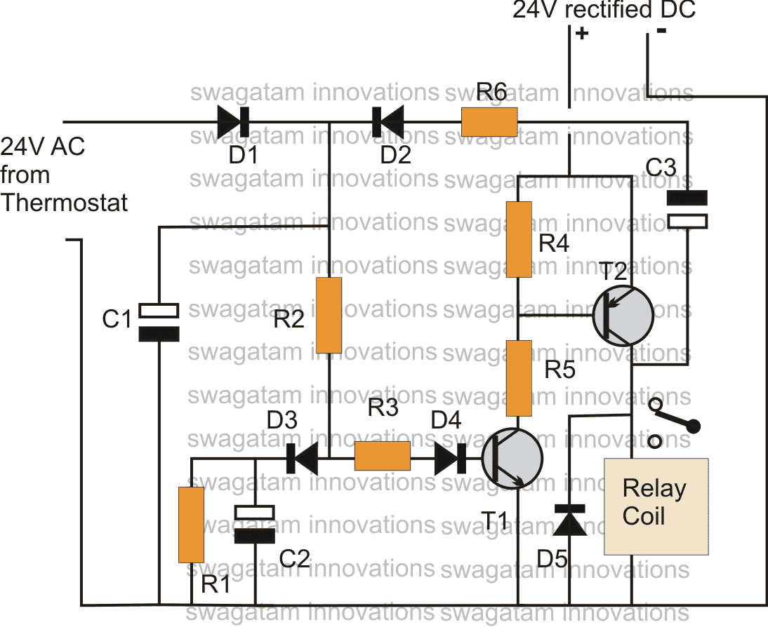
The circuit shown below will respond exactly as per the requested specs. The entire functioning can be understood with the the following points:
When the thermostat "kicks in", the 24V AC is applied across D1 and ground of the circuit. The 24VAC gets rectified through D1/C1 and passes through R2 to reach the junction of R3 and D3.
Since initially C2 is in a discharged state the supply gets grounded via D3 and C2.
However as C2 starts charging up, after a predetermined time (45 seconds) set by the values of R2/C2, the voltage across C2 reaches about 1.4V which becomes sufficient to trigger T1.
T1 conducts and so does T2, pulling the relay into action.
The blower connected to the relay contacts initiates.
After some specified time the thermostat switches OFF.
When this happens, the voltage at the cathode of D1 becomes zero which makes D2 forward biased. such that The instantaneous voltage at the collector of T2 instantly passes via C3, D2 and retains the conduction of T1.
The above situation inhibits the circuit and the relay from switching OFF even after the thermostat has switched OFF.
However now C3 start charging up, and after some predetermined time (45 seconds) set by the value of C3/R6, it gets fully charged and shuts off the base bias to T1.....the circuit and the relay also shut off....until the thermostat "kicks back" again to repeat the procedure.
Parts List for the proposed thermostat timer delay/relay circuit idea
R1 = 100K
R2 = may be replaced with a 1M preset
R3,R4,R5 = 10K
R6 = may be replaced by a 100K preset
D1----D5 = 1N4007
C1,C2 = 100uF/50V
C3 = 220uF/25V
T1 = BC547
T2 = as per the relay coil current


Questions & Answers
Why do you show rectified 24vdc in your schematic, is that aux power out, switched, or an additional or alternative requirement for the circuit to function properly?
It is required for operating the attached 24V relay. This 24V DC can be acquired from the thermostat’s 24V AC.
Hi Swagatam.
I have found your site whilst looking for circuit for a project I want to make.
I have a chicken coop which I want to open and close the door automatically using a photo resistor.
I am not an electronics engineer.
I tried with your circuit using the Wheatstone bridge and a relay to control a motor direction and screw thread ( with micro switches limiting travels).
Whilst this controlled the motor ok, it was closing the door too early.
What is needed is for the closure and opening to be delayed by 30 minutes.
I looked at this circuit as a potential solution to this delay but would appreciate if you could advise if it could be used and what if so what component changes are necessary.
The power supply for the project is a 12v car battery with a solar panel charger.
Thanks
Alan
Hi Alan, I will have to see the schematic of the design that you have employed for the motor. Because we have to ingrate the timer with the input supply that would be coming from the relay contacts, when it switches for opening the motor. So please show me the circuit that you have used so that I can figure out the required connection details.
The above transistorized timer would work nicely for your application if it is integrated correctly.
Hi Swagatam
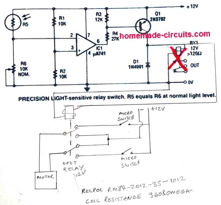
For my testing all I have done is swap the relay in your ‘PRECISION LIGHT-sensitive relay switch’ circuit for a DPDT relay so that when the light fades the 12v high activates the relay to close the door with a micro switch to break the motor circuit when shut.
When light enough the voltage goes to 0v dropping the relay and opens the door, with a separate micro switch to break the motor circuit.
I see this enhancement as being ‘incorporated’ into the LDR circuit prior to the relay being similar to the furnace control, substituting the the LDR output for the thermostat input, and the motor relay for the fan relay, with the additional modifications of 30 minutes delay and 12V supply.
How do I post a picture of the schematic?
Thanks
Alan
Hi Alan, you can post the diagram in any free online image hosting site and provide the link here, if it is possible I will try to solve it for you!
Hi Swagatam
Try this for schematic of my test circuit requiring the delay function.
Thanks
Alan
The DPDT is controlled by the LDR circuit + delay.
The motor and micro switches are all fed directly thru the DPDT connections.
During daylight the DPDT relay is in the unlatched state and the motor circuit is live and opens the door. Micro switch 2 will be made as soon as the door starts to open but the circuit it’s in is not live. When the door reaches the fully open position it breaks micro switch 1 so that the motor circuit is open, stopping the motor.
The relay is still in the unlatched state.
When the DPDT relay is activated/latched by the dark (LDR + delay) the motor circuit polarity is reversed closing the door. When the door is fully closed it breaks micro switch 2 so that the motor circuit is open, again stopping the motor. Micro switch 1 will be made as soon as the door starts to close but the circuit it’s in is not active.
The relay is held in the latched state until daylight by (LDR + delay).
OK understood, so the switches are push-to-off type.
You can probably try the following timer diagram after the opamp stage. Basically you will need to remove the Q1, R3, R4 of the existing circuit and integrate the following timer circuit with pin6 of the op amp
the relay shown in the above circuit will be your DPDT relay
Please add a diode between the R2 and pin6 of the op amp, the cathode will go toward R2 and anode to pin6
Hi Swagatam.
Thanks for your time and effort with the circuit design.
Unfortunately I had accident with my fingers just after the post and have been unable to do anything with it until recently.
I have breadboarded the circuit, setting up the resistance balance point using the original circuit design so that the relay is activated when the light fades. When the circuit is then modified as per the setup above, as soon as the battery is connected to the circuit the relay is activated and stays activated regardless of lighting conditions and the voltage change on opamp pin 6.
You do not provide a spec for T2 and I have used the 2N3702 from the initial circuit design.
Can you advise on any metering checks I can make to diagnose any issues?
Thanks & belated happy new year
Hi Alan,
when you connect the battery you have to make sure that the LDR is in illuminated position. While the LDR is illuminated, the op amp output will be low, which will cause the BC517 to remain switched OFF. If the BC517 is switched OFF, then T2 which is your 2N3702 will also remain switched OFF, and this will finally keep the relay switched OFF.
When the light on the LDR falls below the set level, the output of the op amp will become high, which will cause the BC517, the 2N3702 and the relay to swith ON after some delay,
So please make sure the LDR is amply illuminated while switching ON the circuit. Also connect an LED with 1K series resistor across pin#6 and ground of the op amp. This LED must remain switched OFF while the LDR is illuminated.
There may be some offset leakage voltage output from the op amp, to eliminate it connect the op amp output to the delay circuit via a few 1N4148 diodes in series.
Happy New Year to you also.
Hi Alan, the microswitch needs to latch when it is pressed by the motor. how would the microswitch latch in your circuit? Adding a delay would be even more complex.
AS soon as the motor leaves the microswitch, it would open the switch and break the supply to the DPDT, so the motor would stop. Since the supply is coming from the microswitch, it needs to hold the supply to the DPDT
Hi Tomoly,
The above design is a delay ON timer, your requirement suggests a delay OFF application, so I think you should try the second circuit given in the following link:
https://www.homemade-circuits.com/2012/05/simple-delay-timer-circuits-explained.html
the switch is not required, so its poles may be shorted with a wire link and the LED should be replaced with a relay as done in the above design.
The fan may be wired with the relay contacts.
The circuit will require a 12V DC for operating.
The 1000uF cap is the timing component whose value may be altered for getting the desired delay OFF.