In this post I will comprehensively explain how to protect mosfets and prevent mosfet burning in electronic circuits by following some basic guidelines related to correct PCB layout, and careful manual handling of these sensitive devices.
Introduction
Even after connecting everything correctly you find the mosfets in your circuit becoming HOT and blowing off within minutes. This is quite a common issue faced by most new as well as experienced hobbyists while designing and optimizing mosfet based circuits especially the ones which involve high frequencies.
Obviously, connecting all the parts correctly as per the given details is the main thing that needs to be checked and confirmed first before assuming other issues, because unless the fundamental things are put absolutely right it would be meaningless tracing the other hidden bugs in your circuit.
Basic Mosfet protection application becomes critical specifically in those circuits which involve high frequencies in the order of many kHz. This is because high frequency applications calls for quick (within ns) turn ON and OFF of the devices which in turn demands efficient implementation of all the criteria associated directly or indirectly with the concerned switching.
So what are the main hindrances which cause improper or inefficient switching of the mosfets, I have explained comprehensively how to protect mosfets with the following points.
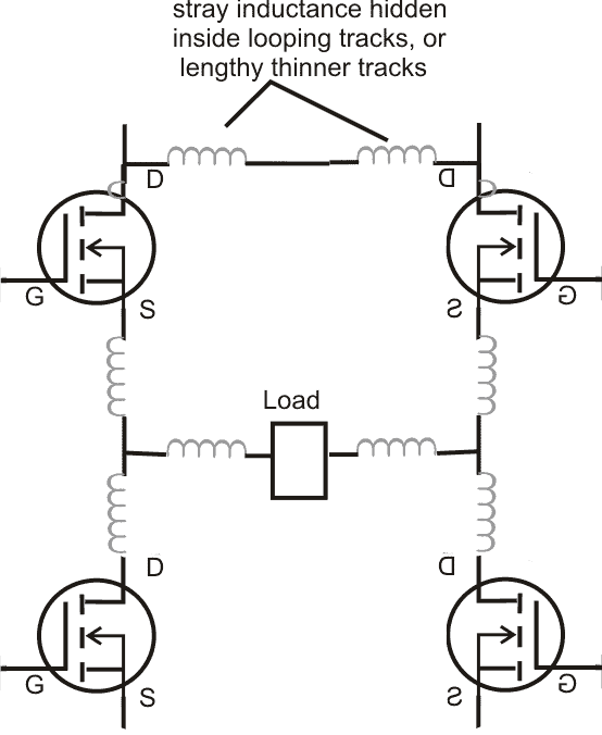
Get Rid of Stray Inductance:
The most common and prime bug in the que is the stray inductance that may be hidden within the circuit tracks. When the switching frequency and current are high, even a slightest unnecessary increase in the connecting path that is the PCB track may result in inter-linked inductance which in turn may affect the mosfet behavior drastically due to inefficient conduction, transients and spikes.
In order to get rid of this issue it's strongly recommended to keep the tracks wider and to keep the devices AS CLOSE AS POSSIBLE to each other and to the driver IC which are being used to drive the respective mosfets.
That's why SMD is preferred and is the best way of eliminating cross inductance across the components, also the use of double sided PCB helps controlling the issue due to its short "printed-through-hole" connections across the components.
Even the standing height of the mosfets must be brought to minimum by inserting the lead as deep down as possible into the PCB, using SMD is probably the best option.
We all know that mosfets include in-built capacitors which require charging and discharging in order to make the device conduct.
Basically these capacitors are connected across the gate/source and gate/drain. Mosfets "don't like" prolonged delayed charging and discharging of its capacitance since these are directly related to its efficiency.
Connecting the mosfets directly to a logic source output might seem to solve this problem, because the logic source would easily switch and sink the capacitance from Vcc to zero quickly, and vice versa due to the absence of any obstacle in its path.
However, implementing the above consideration could also lead to the generation of transients and negative spikes with dangerous amplitudes across the drain and gate making the mosfet vulnerable to the generated spikes due to sudden high current switching across drain/source.
This could easily break the silicon separation between the sections of the mosfet rendering a short circuit inside the device, and damaging it permanently.
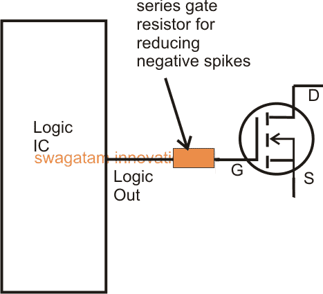
Importance of Gate Resistance:
To get rid of the above issue it is recommended to use low value resistor in series with the logic input and the mosfet gate.
With relatively lower frequencies(50 Hz to 1kHz), the value could be anywhere between 100 and 470 ohms, while for frequencies above this the value could be within 100 ohms, for much higher frequencies (10kHz and above) this must not exceed 50 ohms.
The above consideration allows exponential charging or gradual charging of the internal capacitors reducing or blunting of the chances of negative spikes across the drain/gate pins.
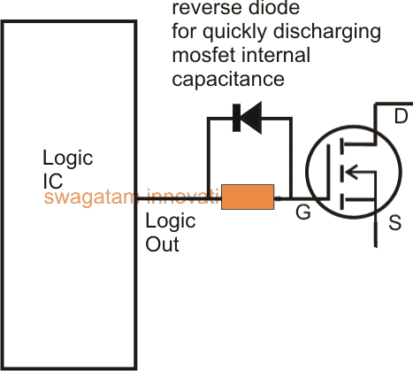
Using Reverse Diodes:
In the above consideration an exponential charging of the gate capacitance reduces the chances of spikes but that also means that the discharging of the involved capacitance would be delayed due to the resistance in the path of the logic input, every time it switches to logic zero. Causing a delayed discharging would mean forcing the mosfet to conduct under stressful conditions, making it unnecessarily warmer.
Including a reverse diode parallel with the gate resistor is always a good practice, and simply tackles the delayed discharging of the gate by providing a continuous path for the gate discharge through the diode and into the logic input.
The above mentioned points regarding correct implementation of mosfets can be easily included in any circuit in order to safeguard mosfets from mysterious malfunctions and burning.
Even in complicated applications such half-bridge or full bridge mosfet driver circuits along with some additional recommended protections.
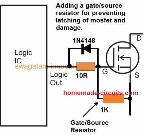
Using a Resistor Between Gate and Source
Although we have not indicated this inclusion in the previous images, this is strongly recommended to safeguard the mosfet from blowing of under all circumstances.
So how does a resistor across gate/source provide a guaranteed protection?
Well, normally mosfets have the tendency to latch up whenever a switching voltage is applied, this latching effect can sometimes be hard to revert, and by the time an opposite switching current is applied it is already too late.
The mentioned resistor ensures that as soon as the switching signal is removed the mosfet is able to quickly turn OFF, and prevent a possible damage.
This resistor value could be anywhere between 1K and 10K, however lower values would provide better and more effective results.
Avalanche Protection
MOSFETs may get damaged if its junction temperature suddenly increases beyond the tolerable limit due to over voltage conditions across its internal body diodes. This occurrence is termed as avalanche in MOSFETs.
The problem can arise when an inductive load is used at the drain side of the device, and during the MOSFET switch OFF periods the inductor's reverse EMF passing through the MOSFET body diode becomes too high, causing a sudden rise in the MOSFET's junction temperatures, and its breakdown.
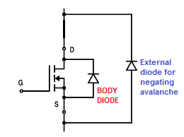
The problem can be tackled by adding an external high power diode across drain/source terminals of the MOSFETs, so that the reverse current is shared across the diodes, and excess heat generation is eliminated.
Protecting Mosfets in H-Bridge Circuits from Burning
While using a full bridge driver circuit involving a driver IC such as the IR2110 in addition to the above, the following aspects should be bored in mind (I'll discuss this in details in one of my upcoming articles soon)
- Add a decoupling capacitor close to the driver IC supply pinouts, this will reduce the switching transients across the internal supply pinouts which in turn will prevent unnatural output logic to the mosfet gates.
- Always use high quality low ESD, low leakage type of capacitors for the bootstrapping capacitor and possibly use a couple of them in parallel. Use within the recommended value given in the datasheet.
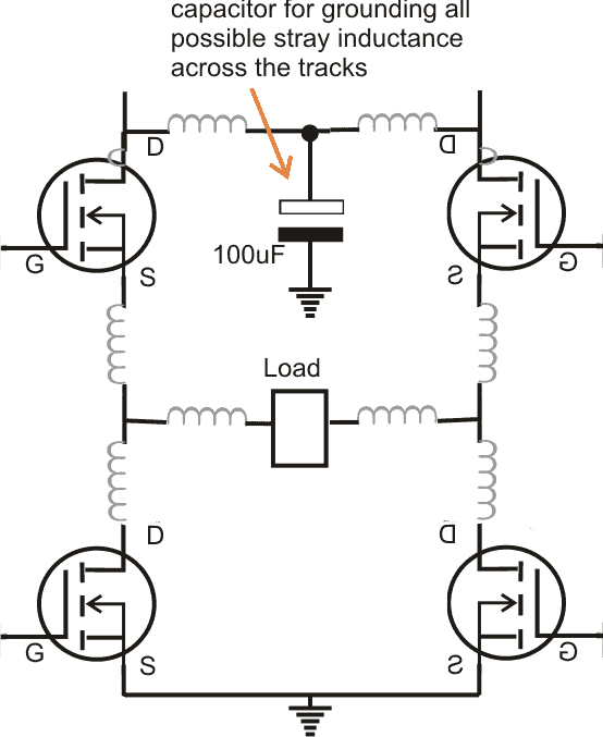
- Always connect the four mosfet interlinks as close as possible to each other. As explained above this will reduce stray inductance across the mosfets.
- AND, connect a relatively large value capacitor across the high side positive (VDD), and the low side ground (VSS), this will effectively ground all stray inductance that may be hiding around the connections.
- Join the VSS, the mosfet low side ground, and the logic input ground all together, and terminate into a single common thick ground to the supply terminal.
- Last but not the least wash the board thoroughly with acetone or similar anti-flux agent in order to remove all possible traces of the soldering flux for evading hidden inter connections and shorts.
Protecting Mosfets from OverHeating
Lighting dimmers often suffer from MOSFET failures. Most dimmers used in low-temperature AC industrial applications are enclosed and often embedded in the wall. This can cause heat dissipation issues, and can result in heat build-up - leading to a thermal event. Usually, the MOSFET used for the lighting dimmer circuits fails in 'resistive mode'.
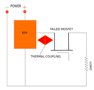
A reflow-able thermal protection or RTP from TE Connectivity provides an answer to MOSFET failure in low-temperature AC applications.
This device acts like a low-value resistor at the normal operating temperatures of the MOSFET. It is mounted almost directly on the MOSFET, and is therefore able to sense the temperature with precision. If for any reason, the MOSFET drifts into a high temperature condition, this is sensed by the RTP, and at a predefined temperature, the RTP changes into a high-value resistor.
This effectively cuts off the power to the MOSFET, saving it from destruction. Thus, a lower priced resistor sacrifices itself to save a more expensive MOSFET. A similar analogy could be the use of a fuse (low-value material) in protecting more complex circuitry (e.g. a television).
One of the most interesting aspects of the RTP from TE Connectivity is its ability to withstand enormous temperatures - up to 260ºC. This is surprising since the resistance change (to protect the MOSFET) usually occurs at around 140ºC.
This miraculous feat is accomplished via innovative design by TE Connectivity. The RTP has to be activated before it starts protecting the MOSFET. The electronic activation of the RTP occurs after the flow soldering (attachment) is completed. Each RTP has to be individually armed by sending a specified current through the arming pin of the RTP for a specified time.
The time-current characteristics are part of the specifications of the RTP. Before it is armed, the value of the resistor of the RTP will follow the specified characteristics. However, once it is armed, the arming pin will become electrically open - preventing further changes.
It is very important that the layout specified by TE Connectivity be followed when designing and mounting the MOSFET and the RTP on the PCB. Since the RTP has to sense the temperature of the MOSFET, it naturally follows that the two should remain in close proximity.
The RTP resistance will allow up to 80A of current at 120V AC through the MOSFET as long as the temperature of the MOSFET remains below the Open Temperature of the RTP, which can be between 135-145ºC.


Questions & Answers
What is the diode value for negative avalanche
You can try BA159…
12v altinda pc817 ile irfz71A mosfet devresini yaptim yuk tarafindan sadece 560mA /12V alabiliyorum oysa bana 5A/12V gerekiyor sorunu nasil cozebiliriz?
Hi, without seeing or understanding the schematic connections it can be difficult for me to solve your query, please explain the connections in details, I will try t help!
Hi Amit,
Calculating the MOSFET gate resistor is not crucial. Mostly it can be any value between 10 ohm and 50 ohms unless the frequency is too high. Lower value resistor is recommended for higher frequencies.
The protection diode should be applied to the high side as well as the low side MOSFETs, and same is true for the 1K gate/source resistor also.
Amit, what will be the battery voltage?
In that case you can use the specified MOSFET, single MOSFETs will be enough since it is rated at 50 amps, which is much higher than 26 amps.
Amit, the VDS of the MOSFeT must be higher than the input DC supply, so for your solar panel volatge which is 246 V, the MOSFeT VDS must be at least 300V, therefore IRFP264N may not be suitable for your application.
Commercial inverters have more features and facilites and are more efficient, that is why they are costlier.
Amit, since IRS2453 is a square wave inverter no cirtical waveform checking may be required and can be built without an oscilloscope, however you will need a frequency meter to check the frequencies.
Amit,
IC 555 or an op amp can be used to convert a square wave inverter to sine wave. But you will need a oscilloscope to confirm the waveform, more can be studied in the following article:
https://www.homemade-circuits.com/designing-a-sine-wave-inverter-circuit-from-the-scratch-tutorial/
For checking frequencies and other partameters you must use a digital multimeter not an utlity meter.
You can add a relay cut off for automatic battery charging.
Hi Swagatam
Thanks for answering.whitch of the two modes is better? an external diode for negating avalanche or drain-gate active clamp?Thanks a lot
Hi Ali,
If possible both must be incorporated, however, according to me a diode across drain/source is more effective and can help to avert avalanche quickly.
Hi Swagatam
How about active clamp for gate-drain? how it works and what is advantage?
thanks a lot
Thank you very much Ali, for your valuable suggestion:
Yes that’s also one of the crucial MOSFET protection networks which can be installed to safeguard a MOSFET breakdown from back EMFs.
An active clamp for MOSFET gate-drain is a parasitic voltage suppressor that incorporates a Zener diode to clamp the gate-to-drain voltage of a MOSFET to a safe value during MOSFET turn-off transitions. This clamping network inhibits the MOSFET from entering avalanche breakdown situation, a catastrophic failure mode that can damage the device instantly.
Hi swagatam,
I’m attempting to learn how to use silicon carbide mosfets in a parallel arrangement.
Infineon says that their coolsic fets can be driven with si fet drivers except that the on has to be 18v and off is recommend to be 0V. I made a half bridge driver and I can get the off V down to close to 0V but not all the way down. When I put a 22ohm resistor across the gate and source it was the lowest (<.2V), but as you say, the resistor heated up. I’ve observed that with a 22kohm resistor it will not turn off. 4.5v (th) with 1000v resistor a single sic fet will do fine at loA and loV.
I need to learn how to drive 16 sicfets @1.3A per fet, 48V. This is for a pulse motor that has 16 coils. 1000W input. I would appreciate any direction that you can offer, I don’t need someone to build the cct for me.
Thanks,
Donald
Hi Donald,
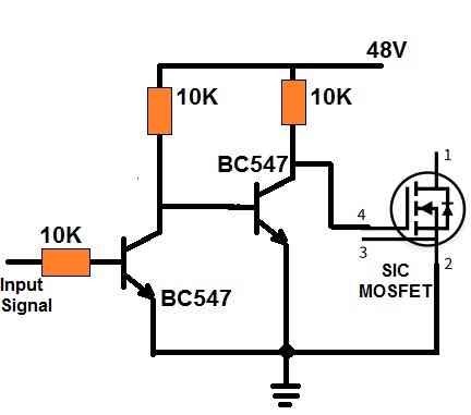
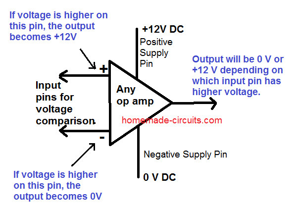
If you want a perfect 0V for switching off the mosfet, then you may have to incorporate BJT stages at the gate of the mosfet, as shown in the following figure:
However I am not sure how to deal with the sense pinout of the mosfet
Thank you swagatam for responding. I don’t understand:
“sense pinout of the mosfet”.
Thanks again,
Donald
No problem Donald, In SIC mosfets there is an extra pin near the gate pin which is mentioned as the sensing pin. I am not sure what it is?
Swagatam,
Thanks for your response.
How would you approach switching 16 sic fets, all at the same time.
About 1.3A per fet, 48vdc pulse motor with 16 air core coils.
1-4 per driver circuit?
I’ll work it out but your wisdom is helpful for reducing my ignorance.
Thanks, Donald
Thank you Donald,
You can connect all the 16 MOSFETs in parallel. Preferably use separate gate resistors for each MOSFET and connect the ends of the resistors together to produce a common gate. Similarly join all the drain terminals together in parallel, and join all the source terminals together in parallel.
Hi swagatam
For the gate to source resistor, when ever I connected in my inverter it always heat up the MOSFET. Please could you know what would be the cost of the MOSFET hating up?
Hi Emmanuel,
That sounds strange, because the gate source resistor is supposed to help keep the MOSFET working without errors and therefore keep the MOSFETs cooler. Which resistor did you use? I would suggest using a 1K resistor. However if your MOSFETs don’t heat up without the resistors then it is better to remove them.
sir can I use 220ohms in the connection of gate to source
No, use 1K or 10K, smaller resistance will cause unnecessary power dissipation.
Hello, thank you for your scientific help. Please explain how to use ir2110 in irs2453 Barsem Figure circuit. Thank you.
Hi, I have not studied Barsem concept yet, so not sure how it works.
Hello sir I have a problem with the three-phase inverter I am making using IR2112 Drivers and TGA25N120ND(25A-1200V) IGBT as a switch.
Whenever I give 35-40V DC as an input of an inverter it will produce around 12-13V AC at the output in each phase without any load at the output.
Problem:
But whenever I try to give more than 100V DC then there is a short circuit across the input DC supply and a fuse connected in series with this DC supply gets burned.
plz help me to find out solution.
How can I give high voltages so that I can complete my project without burning fuses?
Hello Sameer,
Are you using a correctly designed PCB with IGBTs placed very close to each other? Th tracks connecting the IGBTs and the DC lines must be as short as possible and thick.Also make sure to connect reverse diodes across the collector/emitter of the IGBTs, and a reverse diode parallel to the gate resistors. Also make sure to add a 100uF/400V capacitor right across the DC BUS supply lines.
The IGBTs could be burning due to high voltage spikes.
https://www.dropbox.com/sh/3oqctjmogtcli2s/AAAV6_k4bWm8-P9k5nxj7BlRa?dl=0
you can view my PCB by clicking the above dropbox link.
My DC lines, as well as PCB tracks, are short and thick enough according to my knowledge.
The IGBT I am using already has a built-in freewheeling diode across the collector/emitter. Are you talking about this diode or some external diode I need to connect across collector/emitter?
I also use a reverse diode across the gate resistor the only missing thing is a capacitor across the DC supply which I have not used so far.
The first time I used a very thin wire for giving the DC supply to the IGBT-bridge then after the short circuit my wire gets damaged now I am using very good quality thick wire for the DC link but now fuse is connected in series just next to the DC supply gets burned and isolates my IGBT-Bridge from the High Voltage DC.
Any further suggestions?
Thanks for giving me your precious time.
The PCB looks OK to me, but make sure to connect the capacitor across DC bus lines, and it is also recommended to keep the frequency generator IC as close as possible to IGBTs, and connect the input by soldering and not through connectors. Regarding the freewheeling diodes, even though the IGBTs have internal diodes, it is still better to connect external freewheeling diodes.
And while powering the circuit, first supply the low DC to the IC circuit, and after a couple of seconds switch ON the IGBT DC.
Respected sir
Now i encountered a new problem now my 3 phase inverter is working.But When i give 280V DC as input to inverter with 100uF/400V capacitor connected in parallel to input when i switched on my inverter this 280V Dc input drops to around 150V DC.
And I get output of around 80V ac in all three phases.
I am using your recommended capacitor of 400V 100uF.
Can you give me some knowledge why 280V dc input drops to 150V DC when i switched on my inverter.
Please give me some tips how to select input capacitor for DC.
Why you suggest me 100uF/400V capacitor.
I see very large capacitance capacitors in some other inverters like looking like my inverter for example 2200uF/350WV.
Plz guide me why voltage is dropping.Is it due to capacitor or due to some other reason.
Sameer,
The larger the capacitor value, the better will be the response of the circuit and the spike control. You can use 2200uF if you have one
However if the voltage is dropping without any load then the problem is not related to the capacitor. It may be related to the switching pulses or the PWMs for the H bridge.
If the switching pulses are narrow then the output will drop. So you can confirm the switching pulses across the low side mosfet gates whether they are full in size or narrow in size.
I have used IR2100 ic for MOSFET IRFP 460 half bridge ckt high voltage generating for MOSFET output given to High voltage transformer low current but MOSFET failed during main input on off condition.
How did you feed the HIN an LIN inputs and which capacitor did you use for the bootstrapping?
I have connected energy sever lamp in each output of inverter.
These bulb are glowing fine with some minor fluctuations.
First of all I have to say that I’m very glad to here that you are dipIETE holder because I’m also one.
I’m working in the field of power electronics. I just want to ask you a doubt, that is, in an H-bridge
output stage of a sine wave power inverter, can a bidirectional TVS diode connected to the gate/source
terminals of each of the MOSFET banks be able to protect MOSFETs from destruction and is it necessarry
to add this diode in such circuits. If it is necessarry could you suggest any part no. for that purpose.
Thanking you with great happiness
I share the same thoughts as you!, thanks you for posting this question.
I don’t think it is advisable to connect any component across gate/source of the high side mosfets except a high value resistor, although this may be absolutely fine if connected across the low side mosfets.
The high side fets have to work with bootstrapping network, and therefore they may malfunction if a TVS diode was connected between heir gate/source.
You explained all concepts in really simple way and in low rows, I’m a Power Electronics Designer and read a lot Application Note in my job, but this is a very helpful summary
Thanks!
Thank you very much, and I am glad you liked the post!
Dear Sir, please sir can I include all these 3 protections(
1. Including a reverse diode parallel with the gate resistor for quick discharging
2. Using a Resistor Between Gate and Source to safeguard the mosfet from blowing of under all circumstances
3. Avalanche Protection)
on the pure sine wave inverter circuit with RMS adjustment using IC 4047 that you designed?
Or are these protections included already?
Hello Godfrey, only avalanche protection diode would be required in the mentioned inverter circuit, rest of the protections may not be relevant to the design, and can be ignored
Okay sir, thank you very much.
Great explanation. Helped to repair burned SMPS. Thanks.
Hi,
I try to make one inverter , but all of IRFP250 are burn out may i know what is the reason.
i am using 24- 0-24 Tr, Once it work on 12Volt supply.