In this post I have explained 3 simple sound activated relay switch circuits which can used as a module for any system that might be assigned to trigger by detecting some kind of sound pressure level. Or simply applications such as a voice activated alarm security circuit.
1) Circuit Objective
Utilizing this basic sound activated switch design, toggling a system by a sound pulse could be done very effectively, not only with a robotic system but as well as for any desired of home automation.
As an illustration the circuit could be used like a sound-activated light bulb to illuminate a porch light in response to a knock on the front door.
This light would then switch off automatically after some delay. An optional implementation may be in the form of a security protection system.
In this system whenever an intruder aspires to break open the front door or steal a thing, the sound vibrations made during the robbery could then light a bulb or sound an alarm, quickly indicating that someone uninvited has visited your home.
The circuit could work from any 5-12 VDC controlled power source as long as a relay with the appropriate coil voltage is employed.
Video Demonstration
How it Works
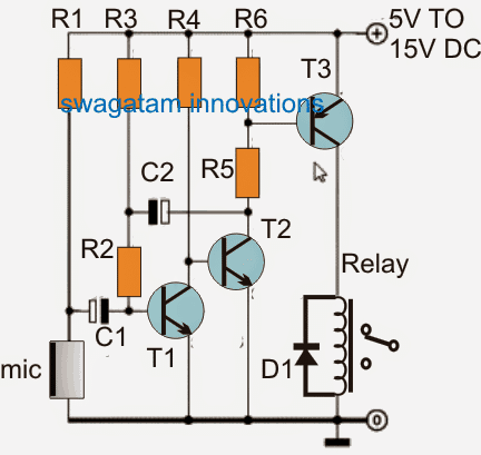
As soon as the sound activated switch circuit is powered ON, you might find the relay activating briefly due to the presence of capacitor C2.
After this, whenever you create a noise in front of the MIC, the relay is going to activate briefly depending on the value of C2 and then switch OFF.
Any AC or DC load connected with the relay contacts will subsequently switch ON and OFF in response to the relay switching.
A couple of seconds must be allowed for the relay to be toggled off. If felt necessary you could to increase or decrease the ‘on’ time period of the relay by modifying the uF C2.
A larger uF contributes to an extended ‘on’ period, and the opposite way round. However, you should not employ a value exceeding beyond 47μF.
Biasing resistor R1 becomes the main part which decides how sensitive the MIC or the microphone can be. Lower values will increase the sensitivity of the MC and the circuit, and vice versa.
An electret microphone commonly possesses just one central FET inside which strictly requires a bias voltage to function.
The best possible R1 value for effective response to audio or noise signal could be determined only through some practical experimentation.
All of the related and essential electronic protection precautionary measures is required to be implemented each time a mains AC powered load is to be connected with the relay contacts.
Parts List
- R1 = 5k6
- R2 = 47k
- R3 = 3M3
- R4 = 33K
- R5 = 330 OHMS
- R6 = 2K2
- C1 = 0.1uF
- C2 = 4.7uF/25V
- T1, T2 = BC547
- T3 = 2N2907
- D1 = 1N4007
- Relay = coil voltage as per the supply voltage, and contact rating as per the load specs
- Mic = electret condenser MIC.
Applications
The concept can be used as a vibration activated LED lighting, for sound triggered recording systems. It can also used as a sound toggled night bedroom light circuit
2) Sound Activated Switch with Customized Sound Frequency
The next project below explains a simple, accurate remote control system through sound vibration that will work on a particular sound frequency.
Therefore it's perfectly foolproof since it won't be disturbed through other unwanted sound or noise.
The idea was requested by Mr. Sharoj Alhasn.
The Sound Sensor Circuit
The figure shows the circuit of a sound detector circuit which can be effectively converted into a remote control, triggered using a sound generator handset.
We have already learned a lot regarding this wonderful frequency decoder LM567 IC.
The IC will lock-on into any frequency that's fed across its input and which exactly matches the frequency fixed across its pin5 and pin6 via the relevant R/C components.
The formula for determining the latching frequency across pin5/6 may be calculated using the following formula:
F = 1 / R3xC2,
where C is in farads, R is in Ohms while F is in Hz.
Here it's set to around 2kHz.
Pin3 is the input of the IC which tracks, responds and locks on an frequency which may be reaching the 2kHz figure.
Once the IC detects this, it produces a zero logic or an instant low at its output pin8.
This low at pin8 sustains as long as the frequency at the input pin stays active, and becomes high as soon as it's removed.
Circuit Diagram
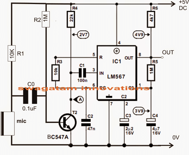
In the discussed sound triggered remote control circuit, a MiC is configured across pin3 of the IC.
An external matching frequency (2kHz) in the form of an audible sound or whistle is pointed toward the mic such that the sound hits the mic starighton.
The mic converts the sound into electrical pulses corresponding to the received frequency at the relevant input pin of the IC.
The IC immediately acknowledges the matching data and reverts the output into a low for the necessary actions.
The output may be directly connected with a relay if only a momentary toggling is required or only for the time the input is active.
For an ON/OFF switching the same may be configured with a FLIP-FLOP circuit.
Sound Activated Remote Transmitter Circuit
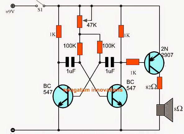
The following circuit may be utilized for generating an audible frequency for the above described sound remote receiver circuit.
The circuit is based on a simple AMV concept using a few ordinary transistors and some other passive parts.
The frequency of this transmitter circuit must be first set to the receivers matching frequency which is calculated to be 2kHz.
This may be done by suitably adjusting the 47k preset and monitoring a latching response from the receiver simultaneously.
Applications
The above explained project which uses foolproof unique frequency for sound triggering can be specifically for remote locks in cars, house doors or safes for jeweler's shops and office entrances etc
3) Alarm Trigger with Sound using Piezo
So far have learn regarding ON/OFF application using noise generation, now let's see how the same could be used for triggering an alarm, whenever a noise or a sound is detected.
A simple sound triggered alarm circuit is a device which is used for triggering an alarm on detection of a sound vibration. The sensitivity of the unit is set externally according to the requirement of the user.
The circuit discussed in this article can be implemented for the above purpose or simply as a security device for detecting an intrusion. For example it can be fitted in a car for detecting a possible intrusion or a break-in.
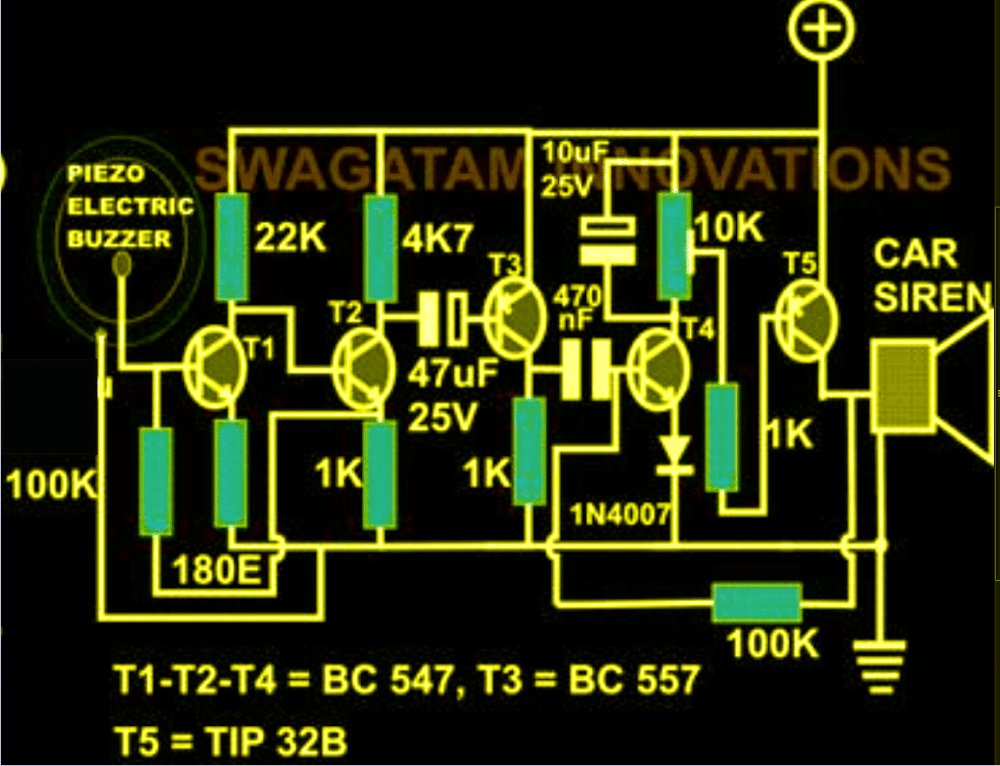
Looking at the circuit diagram we see that the circuit uses only transistors and therefore becomes very easy even for a new hobbyist to understand and make the system at home.
How it Works
Basically the whole circuit is made up of two small signal amplifiers which are connected in series for doubling the sensing power.
T1, T2 along with the associated resistors becomes the first small signal amplifier stage.
The introduction of the 100K resistor across the emitter of T2 and the base of T1 plays an important role in making the amplifier stage very stable due to the feedback loop connected from the output to the input of the stage.
The input of T2 is connected to a piezo transducer element, which is used as a sensor here.
Sound signals hitting the piezo transducer surface is effectively converted to tiny electrical pulses which are amplified by the amplifiers made from T1 and T2 to a certain higher level.
This amplified signal which becomes available at the collector of T2, is fed to the base of a high gain PNP transistor T3 via the 47uF coupling capacitor.
T3 further amplifiers the signals to yet higher levels.
However, the signals are still not strong enough and won't detect the minute sound vibrations, probably which might be emitted by human physical contacts over a particular body.
The next stage which is a replica of the first stage, consists of the transistor T4 and T5.
The amplified signals generated at the collector of T3 is further coupled to the above stage for the final processing.
T4 and T5 makes sure that the signals are amplified to the required limits as per the units expectations.
If the piezo is attached to, say for example a door, even a slight knock over the door will be easily sensed and the alarm connected to T5 will become active.
The 10uF capacitor across the 10K preset keeps the alarm activated for a few seconds of time, its value may be increased for increasing the above delay of the alarm sound.
The discussed sound activated alarm circuit will work with any supply in between 6 and 12, however if the alarm is a powerful one, the current might have to be selected accordingly.
The preset may be used for setting the sensitivity of the circuit.
Circuit Diagram
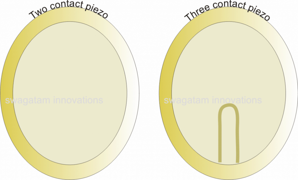
For the sensor, a 27mm piezo transducer will work the best, the following figure shows the image of this device:
Applications
The sound vibration operated switch as explained above looks suitable for creating alarm or siren alarms in response to sound vibrations and therefore could be installed under mats or fixed on doors as safety alarm units.
Whenever a intruder or thief tries to trespass the area by stepping on the mat or opening the door, the sound activates the alarm allowing the user and the neighboring people to get warned about the break-in.



Questions & Answers
Sir ,
Very nice circuit i like this
thanks Mayank!
please comment under the same article, I'll try to help
It's good
nice sir..bahut badiya work krta he yr circuit
Thanks for posting such interesting circuit..
How to cancel Relay chattering effect ( some time happening) while returning NC position ?
How to increase or decrease sensitivity ( louder or low sound) triggering NO position?
to stop chattering, try using a 10uF capacitor parallel to R6….
sensitivity can be increased to some extent by modifying (increasing) the value of C2
Sir,
How can I modify the circuit in such way that another similar sound or clap is required to turn off output (return relay NC position )
regarding your previous reply…
Shorting R6 with 10uF capacitor not behaving to eliminate Infrequent chattering effect.
Bubai, if you are intending to build a clap switch circuit then you can build the second circuit from this article:
https://www.homemade-circuits.com/2011/12/make-simple-electronic-clap-switch.html
try connecting a 100uF parallel to D1, this will definitely solve the issue.
to avoid shattering , use Schmidt Trigger circuit
Sir Can I Remove The microphone And Replace Mp3 out at the point of Mic…. ????
Sharoj, what's your requirement, is it to activate the relay using MP3 signal??
Yes Sir I Need mp3 sound active relay on Circuits. Sir basically I Want To Make An Circuit When this Circuit Get a signal From my Alarm Circuit this Circuit relay will on an i Want To Connect A phone Speed dail i mean 1 button with relay point. So when get a Sound I Will get a Call
OK, then you can connect the junction of C1/R2 and the ground wires with the MP3 input…and the relay contacts configured with the phone speed dial button internally
Hello Sir If Get Any Sound Relay Will Active. But For How many Second ??
How Can i Adjust This As my Wish??
And Sir Another Question Is
How Can I Remove My Phone Microphone And Replace 2 Mp3 out Cable Inthe place of My Mobile microphone
Thank You Sir
Sharoj, yes it will be activated with any form of signal input…you can alter C2 value for the setting the time duration as per your requirement.
I am sure what exactly you are trying to do with your MP3 and cellphone mic….please clarify more for a better understanding.
Dear Sir
I want to Make A System.
I Want To Connect My Alarm Circuit Speaker Out Cable To Your Sound Active Relay On Circuit. When Get A Sound This Circuit Will Get On. My Mobile Speed Dail Number 1 is Connect With This Circuit relay. So when This Circuit get any alarm Then Relay will on. Thn My mobile genate a call . Now
Sir I Want To Remove My Mobile Microphone and Replace Mp3 out line on the point of my mobile Microphone
So Sir How Can i do this ???
Can u help me sir
Dear Sharoj,
I am not sure about how to replace mobile mic with MP3 feed, you will have to consult this with an expert mobile phone technician…
Sir Please Let me know Sir
Thank You Sir For Your Kind Reply.
When This Circuit Get Sound Since 2 or 3 Second Then The Relay Will On.
Sir please Help me
yes the relay stay activated for 2, 3 seconds if the C2 is accordingly selected…
Sir Actually I Want To tell you that
I want Make this System when This Circuit get a Sound Continuesly 2 Second Only then The will Start Working.
for that you will need to connect a 100uF (approximate) capacitor across base and emitter of T3….
Sir How many Voltage For 100 uF Capacitor???
16V or 25V
You can try a "speech jammer" circuit
Sir please help me
i want to modify this circuit. i want like this when, get a sound Continuously 3 seconds Then the relay will energized for 35 seconds . After 35 seconds relay will turn off Automatically. Everything will Reset
Sharoj, you will have to add the following circuit with the above circuit
https://www.homemade-circuits.com/2013/02/make-this-simple-delay-on-circuit.html
remove the relay from the "sound activated relay" circuit and connect the T3 collector with R2 of the linked delay circuit.
make sure to remove R2 end from the positive.
Sir it will Very hard for me . i am basic Hobbist . Sir I want make a nice device with your kind help. i have a good idea . i want to tell you details then i think you will must help me.
So Sir how can i contact with you . and also i can discribe my idea to you.
Please describe it here, I'll try to help
Sir,
I want to make a Circuit which Can Active BY getting a siren Sound since 3 second Continiously …
And relay will Active For 30 Second….. sir please help me easily
It will very helpful for me
then please do exactly as I have suggested in the previous comment…make the two referred deigns separately first and check them separately…
ok….. sir i will try .. if stopped then plz help me
OK
0.1uF/25v?
25V, 50V, 100V anyone will do
Where to place an LDR to turn on a AC lamp at darkness only?
this is not designed to work with an LDR
Hi Swagatam,
I would like to make this circuit more sensitive. I removed the 4.7uF cap so it would follow music and flash a LED. It works but misses some of the sound, so I would like to make it more sensitive. Suggestions please. Thanks! Norman
Hi Norman,
yes removing the 4.7uF cap will remove the latching function of the circuit and will allow instantaneous detection of the input vibrations.
Hi Swagatam,
I think I figured it out. I increased the resistance of R1 and it is now more sensitive to sound. Your comments please.
By changing the R1 value you have changed the MIC’s internal FET’s biasing level, so that might have caused the MIC to become a bit more responsive…you can also try increasing the C1 value and see if that helps to further improve the performance.
Will it work without relay?
you can connect any preferred load in place of relay, it will work
Thank you sir for these sound operated circuits. I was looking for economical projects on home/car security
Thank you Ajay, I am Glad you liked them!
Swagtam ji ,I am in need of a circuit of digital indicator of number of whistle produced by a pressure cooker , i.e. digital indictor shows 1 for the first whistle , 2 for second whistle and so on . The circuit should have a button to reset counter. It can avoid surrounding noise so as to show exat number of whistle. As I am 65 yrs of age some times it becomes difficult to count the exact number of whistle due to doing other house hold work .Thanking u in anticipation……………..P K Bajpai
Hello Pradeep ji, that’s a very good project idea, I’ll surely try to design it soon for you! The challenge is to make the the circuit “listen” to the cooker whistles and not any other sound disturbances…I’ll try to design and post it, and let you know once it’s done!
Thanx a lot Swayam ji I am very much obiliged towards such a prompt attention . Pl. design a circuit without incorporating Arduino or Programmable ICs as I do not have any practical experience on them. Thanking u again ……..P. K Bajpai , Lucknow ,UP
Thank you Pradeep ji, I’ll let you know soon!
Hi Swagatam, I bread boarded the “alarm trigger with sound using piezo” and the buzzer sounds when power is applied and continues. Have you checked this circuit? When I look at the circuit I understand that if T1 is triggered, then T2 will be off and T3 will be off. Will T4 be on and therefore T5 will be on. If T1 is off, then T2 will be on and T3 will be on and T4 will be off and therefore T5 will be off. I really don’t understand capacitors used this way, so I am at a disadvantage. If you have time, please explain the circuit for me.
Hi Norman, it is a thoroughly tested circuit, but looks like an overkill….why don’t you use the first circuit with a piezo?
You can replace the MIC with a piezo and check the response…
for the last circuit you can try connecting an LED in series with the 1K or T3…this LED should remain shut off unless the piezo is knocked.
This will give you a clear idea regarding which stage is wrongly configure or is faulty.
Thanks, Swagatam! The first circuit works very good with the Mic or the Piezo.
Thanks Norman, I’m Glad it worked!
How can this circuit be adapted for 24 volts?
Here’s how I would like to use your design. Our combination scale beeps when an overweight occurs. Workers cannot hear the beep when the cutter in the same room is working (sounds like a wood chipper). I can rig a LED light to flash when the beep sounds (while blocking the cutter sound). I want to tap the 24 volts available in the control package as a power source and keep the relay 24 volts as well.
Regards
Mike
You can use the first circuit with 24V also just by adding a 1K in series with the base of T3, an by replacing the 12V relay with a 24 V relay.
Or more simply just use a 7812 regulator with the first circuit
Hi Swagatam – We would like to plug and aux. speakers into our ham radios, and when the speaker gets an incoming signal/transmission, a LED would flash to let the operator know which radio just had a message.
(We have a line of radios in a van we use – gets loud and confusing at times).
On the LED – I assume a simple ‘Kill” switch would reset it by the operator, but is there a diagram/circuit for the LED to stay on until the operator transmits again? Either way is a start for us – thanks for the help!
JTD
Hi JTD,
you can try the following circuit
the latch can be broken by shorting the 0.22uF capacitor leads.
Thanks! Dumb old guy query – what would be the recommended diodes for the bridge?
Yes, I have been away far to long to remember some basic stuff:) Thanks! JTD
No problem, you can use 1N4007 diodes for any bridge rectifier network
Hlo,
The pressure cooker whistle counter project concept is vey nice.
Can you give us the whole circuits discription and how it is going to work.
And also about how to alert the customer after 5 counts.
Thanks and Glad you liked it.
The entire explanation is presented in the following link
https://www.homemade-circuits.com/pressure-cooker-whistle-counter-circuit/
My neighbor has a 22kW 240V generator unit 25′ from my bedroom window separates by a fence and his house. He does not care about his noise waking others up. So I am looking to buy a module with an adjustable input sound pressure level (range of 57dB to 87dB) to close a relay horn that I can locate near his bedroom to make to 97dB of noise. His bedroom window is 75′ diagonally opposite mine.
Sorry, I don’t sell electronic items in this website!
Thank you very much for the prompt reply!
I would like to wire in the existing mic/speaker in a security camera in place of the condenser microphone in your schematics. Is this a problem or what changes do you recommend in order to do this? My idea is that i could “activate” the security camera mic/speaker function from my phone app and speak, whistle, actually make any sound and it will activate the relay. Really enjoy your ideas and have subscribed to your newsletter.
What is the output like that you get from the mic/speaker unit? If it is a positive voltage then you can replace the MIC in the first design with an NPN transistor with its base connected to your mic/speaker unit’s output via a 100k resistor. However, the relay is not a flip flop type, it will remain activate only for sometime and then switch OFF until an input is detected….I am glad you subscribed to my newsletters.
Do they make a switch that can turn on if noise hits a certain decibel and then switch back within 2-5 minutes of no more sound at that decibel? I have a parrot that sometimes gets extremely loud. the only way to make him be quite is cover him. I want to have my automatic shades go down when he start squawking and draw back up after 5 minutes of being quite. I have no background with building circuits, so looking for a device that currently exists. Thank you for your advice!
Sensitivity can be decreased by increasing the value of R1, you can try 22k or 47k for R1 and see the difference…however, the operation can create a lot of stress for the parrot, which may be already in lot of stress due to caging
Please confirm that your listing a resistor as “3M3” is equal to 3.3Meg ohms. I haven’t seen this notation before. Thanks!
Yes 3M3 = 3.3 Meg Ohms
Hi, Swagatam. My dad recently passed away leaving my elderly mom living by herself on a farm. I installed a simplisafe alarm system to give her, and me, some peace of mind. Everything works well except for the exterior siren. It is just not loud enough – you can barely hear it from the shop (about 150′ away), so no way it would act as much of a deterrent, let alone alert the neighbors (closest ones are about 1/4 mile away.) So I’ve been hunting around to try and find a relay that I could place close to the simplisafe siren (so something about 85 db), that would turn on a separate, louder siren on ONLY while the simplisafe siren is activated. Thus far I’ve had no luck. I have two sirens, one that’s powered by 110V, the other low voltage. I’m a mechanical engineer and have done a lot of electrical wiring work so am very comfortable around 110, but have done very little in the way of circuits (vaguely remember stuff from a class almost 40 years ago ….!) Any help you could give me would be greatly appreciated. Thanks!
Hi Paul, the first circuit from the above article is exactly what you need. The sensitivity of the circuit can be controlled by adjusting the R1 resistor. Lower values will increase the sensitivity and vice versa. The capacitor C2 decides for how long the relay stays activated after the sound input has stopped.
Regarding….. 2) Sound Activated Switch with Customized Sound Frequency
Can thisbe built to acitvate a relay when a 500 khz sound is picked-up?
If so, what would the values needed be for the R2 and C2?
Also, any ideas on how I can use the input to a piezo alarm speaker to control a relay?
I have a simple transistor ckt that works across a regualr speaker input but when I put that ckt across the piezo the volume is greatly reduced.
When used with a conventional speaker the volume is not effected.
Yes that is possible, but 500 kHz is the maximum detection range of the IC LM567, beyond which its range diminishes.
You can get the formula for the frequency in the following article:
https://www.homemade-circuits.com/lm567-tone-decoder-ic-features-and/
To drive a piezo you will need an inductor parallel to the piezo for amplifying its output. Without a high frequency, and an inductor the piezo will not amplify the input signal.
Hello:
I doubt I receive a reply, but I thought it would be worth a try because of the interesting topic.
I have a rare toy from the 1960s called Charm the Cobra. It was made in Japan by the Poynter Products Co. of Cincinnati, OH. It’s incredible in that it uses sound activation technology of the period. The idea is when you blow a little plastic flute that comes with it, a toy cobra rises up out of the “snake charmers” basket. When you stop blowing the flute, he goes back down. It’s quite incredible. I am in the process of trying to restore it (it’s actually in pretty good shape internally), but I have little understanding of how the squeaky little sound from this cheap little plastic flute can make the cobra actually rise up the wire he is attached to. There is a tall plastic cylinder with a thin circular metal disk on top with a thin needle-like device attached. Kind of looks like a record player. I also see a resistor attached.
There is a reverse polarity motor and a whole bunch of wires going to various connections. It runs on three C batteries.
I can understand the motor part, but the sound activation portion escapes me, hence, I thought I would write to ask for some possible advice on how to approach fixing this incredibly rare and rather cool toy. I would attach a photo, but I do not see the option.
Thanks for looking,
Cody
The toy must have been really interesting. The toy appears to be more complex with its mechanical assembly rather than the electronics. In the electronics sections there could be a sound sensor which keeps the motor switched ON as long as the sound from the flute is available. While the flute sound is present the motor is held operational allowing the snake to unwind and rise. However, yes, if the toy is designed to respond only to the flute sound, then it is indeed marvelous, in today’s modern world we use the IC LM567 which can be wired to sense only a specific sound frequency and reject the other sound frequencies, but I am not sure which IC they might have used in this fascinating toy.
Thanks so very much for your reply. I tried sending photos, but I do not know if you got them or not. I apologize if I come off as a little eager…it’s just that I sure would like to better understand how the system works and get it working. How it manages to activate by the little squeaks made by this tiny toy flute is beyond me. If you don’t mind, I would like to send you photos of it if you’re intrigued by such a device. There are no ICs that I can see, but there is a resistor atop the cylindrical object that has a very thin tin circle on top with what looks like a phonograph arm attached. It looks like a little record player. Could it be this is how it works…similar to a record player or primitive recorder by capturing the sound from the flute and relaying it to the motor somehow?.
I would have certainly liked to see the images, however, unfortunately there’s no image uploading facility available in this platform. There’s an alternative way of doing it. You can upload the images to any online free image hosting site and then provide the link to me here. Please remove the https while submitting the links otherwise the comment will be sent to the spam folder.
Wow, thanks for your interest and willingness to advise. When you have time to take a look, here are links to the images:
https://ibb.co/YX6yXwW
https://ibb.co/xjvz7wN
https://ibb.co/TLRVZhn
https://ibb.co/kJ5fYZ9
I hope they open. I can add more if needed. Note the little “record player” looking thing atop the cylinder with the tiny stylus. I had the theory that it worked something like a primitive Edison recorder with the thin tin disk and a small stylus that moves back and forth to record the sound from the flute, then, somehow, sends it to the motor. I don’t know. It just reminds me of that. How that would activate the motor to raise the snake is confounding and amazing.
All the best,
Cody
I tried to open the links, but none of them are opening. It is showing “this site cannot be reached”
I forgot to remove the
Here they are:
ibb.co/YX6yXwW
ibb.co/xjvz7wN
ibb.co/TLRVZhn
ibb.co/kJ5fYZ9
I hope you can view them. Thanks very much for your willingness to advise. I think it may work like an old Edison recorder. Note the little tin disk and stylus on top of the cylinder. I don’t know, it reminds me of that anyway.
Thanks much,
Cody
Even these links without https are not opening, not sure what may be the problem?
This is strange. Making it so you can’t post images is weird.
I’ll try one more time.
://postimg.cc/gallery/y8FCBRX
Thank you for the images! Yes I can see the images now although they are quite small to notice the fine details. Yet still I can see the mechanism which is intriguing, but highly complex to copy or replicate at our level.
I can try to resend bigger images.
But do you have an idea how it might work?. Under the plastic cap, there is a little thin metal disk with a stylus, and a wire going from that cylindrical object to the polarity switch for the motor; does it work kind of like an old Edison recording device?. There is a resistor at the top you can see in one of the images.
My expertise is limited to designing small electronic circuits, so honestly I don’t think I would be able to understand the mechanical details of the system.
Okey-doke. Thanks for your input.
All the best, Cody
Hello
What adaptions would be required to create a switching system to break a mains circuit when excess sound levels are encountered such as loud music in a quiet zone ?.
A relay would be sufficient to control a mains contactor and the off period would need to be variable.
I cannot find a device to operate in this way and this may be a commercially viable project for you.
Hello, you can use the first circuit from the above article for implementing the process. R1 controls the sensitivity of the circuit, and C2 value determines how long the relay might stay activated once the relay is activated.
Hi, I love your circuit for “the sound sensor circuit”, also “the sound activated remote transmitter “ circuit. Rather than build several sound sensor circuits to activate several different relays, I was wondering if there is a circuit that can respond to more than just one frequency. Example… frequency A will only activate relay A. Frequency B… only relay B
Hi, The second circuit in the above article is designed to respond to specific frequencies as per the adjustments.
hello Mr. Swagatam
I’m 70 and a beginner in this field you have inspired me to develop new skills.
r6 is it a 4k7. I have 4.7k are they the same.
C0 C1 C2 the N after the value does it stand for non – polarizes capacitor?
C0 0.1uf larger than the rest on circuit diagram. Doesn’t seem to indicate a connection point.
The A in a circle is this an amp location.
C3C4, are they polarized. Top positive bottom negative.
2 ohm 2 ohm is that the value and what is 16 volts relate to in the circuit.
Thank you Karl, glad you found my articles inspiring.
yes, 4k7 = 4.7 k
nF stands for nano farad.
0.1uF is larger than C1 and C2, it connects between transistor base and the MIC.
Please ignore the A, it is not relevant to the circuit
Yes C3, C4 are polarized, top pin is the positive pin
2u2 = 2.2 microfarad, and 16 is its maximum tolerable voltage limit.
circuit with L 567 can pin 8 activate a relay
do i need to change value of capacitor to control latch on/off
Goal of this project would be triggering alarm on remotely and have to have a notification sent to a cell phone if an intrusion was to occur.
do you fill this is possible?
love the help have been. sharing information about you to some of my old friends at Disney.
thanks agin
Thanks Karl, I don’t think a relay can be used directly with the pin#8 of the IC, you will need a transistor driver for it.
This circuit cannot be latched. The capacitor value cannot be changed to latch the circuit
would the 433 MHz remote Infared wireless alarm be a better fit for the Bluetooth car ignition lock out circuit.
is there an alarm sounding device that could replace a siren horn dc 12 v 6 tone from amazon.
Hi
I am new electronics and trying to build a sound activated buzzer that goes into a toy. I need to turn it on from 25 to 50 feet away in order to locate the toy. Voice or other small noisemaker would work. Can this be built using a coin battery?
Where would I find someone to make a prototype or a hundred or a thousand of these?
Thanks for the info above!
Jerry
Hi, you can try the first circuit but I don’t think it can work with a coin battery. You will need a at least 5 V to operate it normally. You can replace the relay with a buzzer.
Also 40 to 50 feet looks quite a large distance which would require a significant amount of noise to activate it. You can increase its sensitivity by adjusting the value of R1.
Sorry, I have no idea from where you can get this product manufactured.