A simple 50 watt amplifier circuit is I have explained below, I have explained how to build it at home using this versatile single amplifier chip LM3876T
By: Dhrubajyoti Biswas
UPDATE: For 40 watt amplifier circuits please visit this link.
Analyzing the Circuit
A good power amplifier is a necessity, especially when it comes to listening music. An amplifier added to a sound system will definitely enrich the quality of music.
This project therefore will attempt to give you a detailed insight of making a simple 50 watt power amplifier.
The system that we are going to deal with is primarily based upon the technical specification laid out by National Semiconductors, and following this the result came out well.
Easy to build and good output in terms of distortion and noise, the following section will detail the way it is built.
Before we kick-start this development, we have tested the PCB and result came out positive.
We have received very good sound quality provided the protection circuitry is not in operational mode.
The last stable version of the board ESP P19 (Rev-B) has few alterations, such as, the connection to the sound impairment monitor [SIM] has been taken out.
The following Figure is a layout of the original board:
Board Layout
Circuit Operation
As per the diagram, there is an addition of polyester bypass capacitors and the mute circuit is left disabled, since it is mainly useful when developing a preamp.
However, we made some adjustment into the board to provide space for power and input connectors.
As per the above figure, the voltage gain is set to 27dB, and it can be changed by adding resistors of different value for the path of the feedback.
The inductor has 10 turns of enameled copper wire of 0.4mm and is wounded around the body of the 10 ohm resistor.
The soldered wire lies at the end of the resistor and the insulation should be brushed off on each end.
Our recommendation would be to use 1watt type 10ohm and 2.7ohm resistors. The rest should metal film of 1%. It is also ideal to keep the electrolytic capacitors @ 50V.
For supply, 100nF (0.1uF) should be placed near to the IC in order to avoid oscillation. The voltage supplies to maintain at full load should be around +/- 35 volts, which would produce 56 watts (Max.).
Also to achieve lowest case to the heatsink thermal resistance it is vital to engage max power.
This can be done by mounting mica washer with no insulation. However, do keep in mind the heatsink need insulation from the chassis since the heatsink maintain supply voltage of –ve.
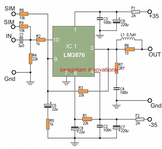
The following schematic in Figure shows the changes we made on the original board:
Referring to Figure above, the revised board is very much similar to that of the original one, except some changes by removing some components along with the SIM.
The present on-board decoupling gives great performance. It uses electrolytic of 100nF Polyester and 220uF electrolytic.
Alternatively, you can also use monolithic ceramic capacitor on every rail. While C1 and C2 is referred as polarized electrolytic types, you may use non-polarized electros.
Another option would be to apply on C1 a 1uF polyester cap. If C1 is intended to be used as tweeters you can use small values of 100nF which is good to go ahead.
If you are building the proposed simple 50 watt power amplifier circuit to use it for biamped/triamped system tweeter or midrange, the C1 valued need to be reduced to 100nF (3dB @ 72Hz).
Also you can use 1uF polyester at the rate of -3dB @ 7.2Hz in case of any general use. However, this adjustment would increase the performance of the bass and you can also apply any value till 10uF (approx.) on C1 if needed to do so.
The new design of the PCB facilitates using the amp as dual-mono. You can split the PCB track while each individual has its own power supply.
While the IMO carries less point, this enables cutting the PCB in half with each halves has its own supply.
The board gives the facility to make output connection to the PCB pins, or by using PCB mount spade lug.
Upgrading the Design
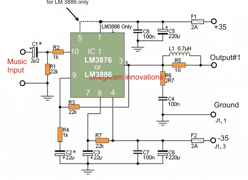
As per the board’s design shown in the figure, you can use LM3886. It is very much identical and moreover the specification is higher.
The PCB also have the provision to connect pin number 1 and 5. Furthermore, you can also use the board as a bridge in case of LM3886 to achieve 120W into 8ohms.
Our suggestion would be to use P87B to enable out-oh-phase signal that is needed to operate BTL.
To run an amp as inverting is a common occurrence, but doing that ends up with low impedance to the preamp, which may give trouble as you may find distortion or problem in loading.
Therefore, it is always safe to drive the amplifiers, since the P87B can drive each amp individually.
Whereas parallel operation is often a common suggestion when building this system, our experience in this domain does not recommend the same.
The requirements for gain tolerance during parallel operation is very strict as you need to ensure the amplifier matches 0.1% or keep it over the entire bandwidth.
Now since the impedance of the IC has low output, therefore even 100mV may end up generating high circulating currents via the IC’s.
As 0.1Ω comes as usual suggestion, a mismatch of 100mV may end up 0.5A of circulating current, which ends up in overheating.
Pinout Diagram
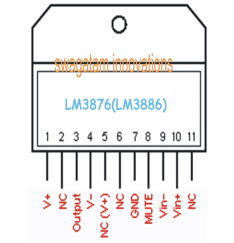
Figure above shows the IC pinouts for LM3876 where the pins are staggered to enable the PCB tracks run into the pin of the IC.
The LM3886 on the other hand is very much identical to the former, and it can be used by adding little more power, if needed.
However, the only difference that lies between the two is in LM3886 it is mandatory for Pin 5 to connect to +ve supply.
The PCB used for this amp is mainly meant for stereo amplifier. It is single-sided with the location of supply fuse in the PCB. The stereo board contain small four fuses (115mm x 40 mm).
Overall the revised board as in Figure 1.1 is of the same size to that of the original (as shown in Figure 1.0) and we have applied similar spacing in between the IC’s to facilitate retro-fitting, if needed.
However, as a caution do keep in mind to use heat-sink for this project as the system gets really hot within a short time, which may end up destroying the things from overheating.
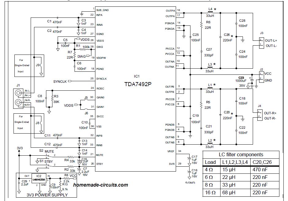
Using TDA7492 IC
Another very nice 50 + 50 watt stereo class D BTL amplifier can be built using a single IC TDA7492.
Complete circuit diagram for this circuit can be seen below:
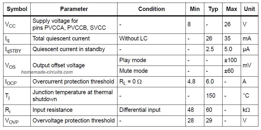
Absolute Maximum Rating of the IC TDA7492
- VCC DC supply voltage for the IC not to exceed = 30 V
- VI Voltage limits for input pins STBY, MUTE, INNA, INPA, INNB, INPGAIN0, GAIN1 should be within = -0.3 - 3.6 V
- Maximum IC case temperature which must not exceed is = -40 to +85 °C
- Maximum Tj Junction temperature of the IC not to exceed = -40 to 150 °C
- Tstg Storage temperature must be between = -40 to 150 °C
Main Electrical Specifications
Simple 50 Watt Amplifier using Transistors
The following image shows how a simple 50 watt hi-fi amplifier circuit could be constructed quickly using ordinary transistors, and resistors.
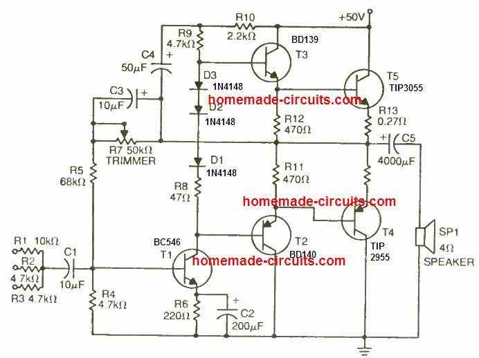
The 50 k preset helps to set the gain of the amplifier to the preferred limits.


Questions & Answers
Thank you very much Engineer,God bless you more for your kindness
Ok thanks, can I use 12v DC to 35v DC boost converter circuit to power the 50 Watt Amplifier
Yes, you can use it…
Please ( 1). what is F1(2A) connected to +35 and F2(2A) connected to -35,. and J1, 1 and J1, 3 at the output of the IC LM3886. (2). Is there need to add heatsink to the Amplifier circuit, where to put the heatsink if needed. (3) what is SIM and what is the function
F1, F2 are fuses.
SIM = Signal Inversion Mode
Heatsink to be fitted on the IC metal tab…
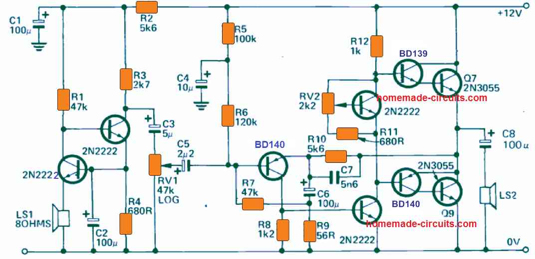
HI Swagatam could i increase power output of the simple 50 watt ampifier by adding more power transistors
Hi Wayne, referring to the last circuit, you can probably increase power by making the output power transistors into Darlington versions.
My name is Robert Ojiambo,from kenya. I am an electronics Technician,with 20 yrs in electronics repair and service industry. Mr Swagatam,i would like to thank you generally for the great work you have done in electronics for both the beginers as well as those already in the field. My wish is to know whether you have a whatsup group that I can join. So far am interested in robotic electronics and led lights programing.
You are most welcome Mr. Robert, I am glad to know about your experience in the field of electronics.
Currently I do not have a WhatsApp group, if I make one in the near future i will surely let you know.
All the best to you, and do keep in touch.
So sorry, the 50k preset adjusts the voltage at half the amp’s psu at the junction of E resistors and coupling Cap!
Good day sir, this ic LM 386 is not found in my which of the ic will I use to replace it
Daniel, LM386 is very common IC, if that is not available then other variants may also be impossible to get. you can try this:
https://www.homemade-circuits.com/lm4862-amplifier-circuit-better-lm386-alternative/
you can try the first circuit from this article
https://www.homemade-circuits.com/2012/08/ic-lm-386-datasheet-explained-in-simple.html
hi i need a power amplifier with gain 10 will you help me to find the circiuts