In this post I have explained the main specifications, datasheet and working principle of the IC LM567, which is a precise phase-locked loop with synchronous AM lock detection and power output device.
In simpler terms the IC LM567 IC is a tone decoder chip which is designed basically for recognizing a specified frequency band, and activating the output in response to the detection.
Needless to say this chip can be used for a number of different applications, the most common being in the field of remote controls, and security systems.
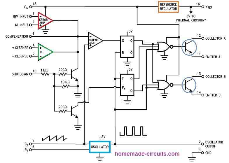
Block Diagram
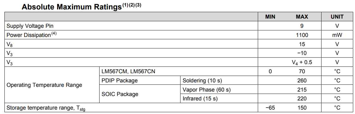
Absolute Maximum Rating
Absolute maximum rating refers to the values indicating the maximum tolerable capacity of the IC in terms of voltage, current, and power dissipation. The following table explains the absolute maximum rating of the IC LM567 for the relevant parameters:
Pinout Working and Specifications
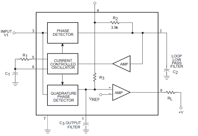
Referring to the the above shown IC LM 567 internal configuration diagram, the pinout function of the IC may be understood from the following points:
Pin#4 and Pin#7 are the positive (Vdd) and the negative (Vss) supply inputs respectively for the IC.
Pin#3 is the sensing input of the input, which is used for detecting a given phase-locked loop frequency, in other words this pin will lock-on with the matching center frequency which may be set inside the IC through a pair of external RC network.
The Pin#5 and 6 are used for creating the center frequency by setting up the values of R1, C1 as required, and this frequency is used by the sensing input pin#3 to lock-in and create a logic zero at pin#8 which is the output pin of the IC.
Output Pin#8 is normally logic high and becomes logic zero as soon as a matching frequency is detected at pin#3 of the IC.
Pin#1 and pin#2 are used for ensuring proper filtration of the involved frequencies so that the IC does not create any false output due to any existing spurious or stray noise interferences.
Main Features of LM567:
Extensive settable frequency range (0.01 Hz to 500 kHz), meaning the sensing passband may be set right from 0.1 to 500 kHz, giving an option of a huge range so that unlimited unique configuration can be achieved from this chip.
Highly stable of center frequency, which assures precise passband limits making the unit very reliable with the detection functions.
Independently controllable bandwidth (up to 14%), as the feature suggests, the bandwidth is also adjustable to a reasonable degree.
High out-band signal, and noise rejection, which again assures high reliability during the detection and implementation of the said functions.
Logic-compatible output with 100 mA current sinking capability, which allows the output to handle relatively higher loads without employing an additional buffer stage such as a transistor driver stage.
Inherent immunity to false signals, which ensures that the chip never produces false results due to incorrect frequency detection or in the presence of stray or spurious instantaneous signals.
Frequency adjustment over a 20-to-1 range with an external resistor, this feature again makes the chip highly flexible and dynamic.
The three important Parameters Associated with the IC LM567 may be understood with the following points:
Phase locked loop center frequency
It’s the free running frequency of the in-built current controlled oscillator circuitry in the
absence of an input signal.
Detection Bandwidth
This is the frequency range which may be provided to the above center frequency, within which the presence of an input signal having a threshold voltage of above 20mV causes the output of the IC to become low. This feature refers to the loop capture range.
Lock Range
It is the maximum range of frequency which would enable the output to switch to logic zero in the presence of a relevant input signal having a threshold voltage above 20mV.
Detection Band
It is the magnitude which indicates the level of optimal detection, focused around the center frequency. It’s given by the formula:
Detection Band = (fmax + fmin – 2fo)/2fo,
where fmax and fmin are the frequencies thresholds of the detection band, fo is the center frequency.
Application Hints
The IC567 may be considered as a versatile chip because it provides an unlimited range of applications in the field of electronics, some of them are discussed below:
- Touch-Tone decoding: The human touch response may produce different frequencies when employed with this chip, it can be suitably decoded by using many IC LM567 configurations.
- Carrier current remote controls: Our existing mains wiring can be very effectively used as a medium of transfer for communicating between the rooms or for controlling appliances remotely from one room to the other. The actions can be implemented by using a LM567 IC.
- Infrared controls (remote TV, etc.): Since the center frequency of LM567 is tightly locked, it may be used for detecting IR waves precisely from the given handset. Unlike ordinary IR remote controls, this circuit is better immune to stray RF or IR disturbances created from switching AC mains appliances.
- Frequency monitoring and control: Again since the LM567 IC has an inbuilt precise frequency detection range, which can be used for monitoring a given range of frequency accurately.
- Wireless intercom: Just like Carrier current remote controls, the IC LM567 may also be suitably implemented in wireless intercom systems.
- Precision oscillator: The phase locked loop feature in the proposed IC also facilitates its application as a precision oscillator for achieving precisely adjusted oscillations or frequencies.
Summarizing More Information About LM567 IC
The LM567 circuit is an active filter most commonly used as a frequency decoder. The LM567 circuit detects and responds to a specific frequency that can be set and adjusted in advance. It is an IC with a wide range of diverse applications, particularly in the field of remote control.
General information:
- Its nominal working power supply potential is 5V DC. It consumes approximately 7 mA.
- It is an extremely complex integrated circuit, consisting of no fewer than 62 transistors!
- With the help of a minimal number of peripheral components, its usage is very straightforward.
- In particular, by using an adjustable RC component, it is possible to vary the detection range in a ratio of 1 to 20.
- Its output can accept a current compatible with TTL technology (up to several tens of mA).
- The bandwidth is adjustable from 0 to 14%.
- Naturally, the circuit is equipped with an effective noise rejection and immunity device against noise and parasitic signals.
- It is characterized by a high stability of the frequency setting value. The frequency itself can be adjusted within very wide proportions, ranging from 0.01 Hz to 500 kHz.
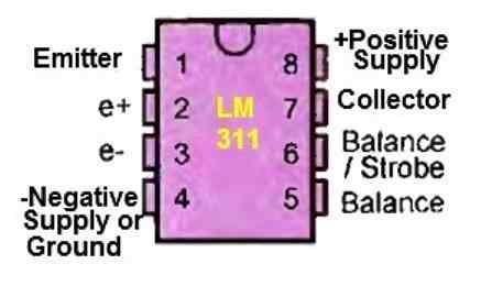
The IC is represented in the form of a rectangular package with 8 pins, arranged in two rows of 4.
The positive power supply is connected to pin 4, while the negative (ground) connection is made to pin 7.
The input signal is applied to pin 3, and the output is available at pin 8.
Pins 1 and 2 are connected to capacitors that are linked to the negative power supply.
The first capacitor filters the output signal, while the second capacitor determines the bandwidth width.
Finally, pins 5 and 6 are connected to a capacitor and a typically adjustable resistor, respectively. These components determine the detection frequency parameters.
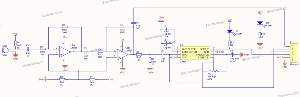
Application Circuit
Referring to the example circuit shown below, the signal applied to pin 3 can take the form of a sinusoidal waveform or a square waveform, symmetric or asymmetric.
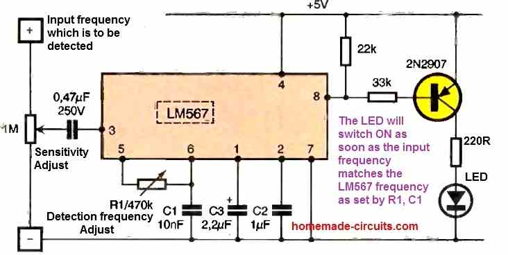
However, the manufacturer recommends an RMS (root mean square) value ranging from 50 to 200 mV.
For a sinusoidal signal, the RMS value is determined by the relationship: Veff = 0.35 x Vpp (where Vpp is the peak-to-peak value).
If the signal is a square waveform, the RMS value is calculated using the relationship: Veff = Vpp / 2 (where Vpp is the potential difference between the high and low levels).
If the signal includes a DC component, which is often the case, it needs to be blocked by using a coupling capacitor at Pin 3.
Pin 6 should be connected to ground through a capacitor, denoted as C1.
Pins 5 and 6 are connected by a resistance, variable or fixed, denoted as R1.
The detection frequency is then determined by the relationship: FO = 1 / (1.1 x R1 x C1) (where R1 is in ohms and C1 is in farads).
The internal circuitry employs the principle of phase lock loop.
By using a capacitor, denoted as C2, connected between pin 2 and ground, the bandwidth width can be determined as a percentage relative to F0:
Bandwidth (%) = 1070 (√Veff / FO x C2) (where Veff is in volts, FO is in hertz, and C2 is in picofarads).
The capacitor C3, which connects pin 1 to ground, plays a role in determining the number of input signal cycles needed for detection confirmation.
By selecting a value for C3 that is close to the value of C2, this number of cycles varies inversely with the width of the bandwidth.
For example, if the bandwidth width decreases from 10% to 0%, the required number of cycles for triggering the detection will increase from 30 to 300.
This feature provides an additional means of ensuring that only desired signals are detected while minimizing false detections.
Furthermore, when FO (the target frequency) is detected, the output at pin 8, which is normally held high by a resistor (ranging from 10k to 100k) connected to the positive supply, rapidly switches to a low state, providing a clear indication of the detection.
Questions & Answers
Hello,
thanks for you valuable article about the LM567. I decided to use the LMC567 -because of the possibility to work with much lower voltage- to detect the tone of a doorbell, but I don’t get the chip running. I learned, that the LMC has other needs for capacitors, so I went ahead, using the values from the example circuit in the datasheet, and calculated Ct and Rt with the formula from the TI datasheet (https://www.ti.com/lit/gpn/LMC567).
I have described my problems in this forum https://www.mikrocontroller.net/topic/582610#8014077 (in german), but you can see the schematics and the input and output signal.
I calculated for the 175Hz frequency, but currently the LMC567 generates random rectangle output , as soon, as the input frequency goes over 70Hz. The output does not change its behaviour, when increasing the frequency up to 1kHz. So nothing about the expected behaviour.
Do you have any idea, what I have done wrong?
Hey Nick,
I checked your schematic..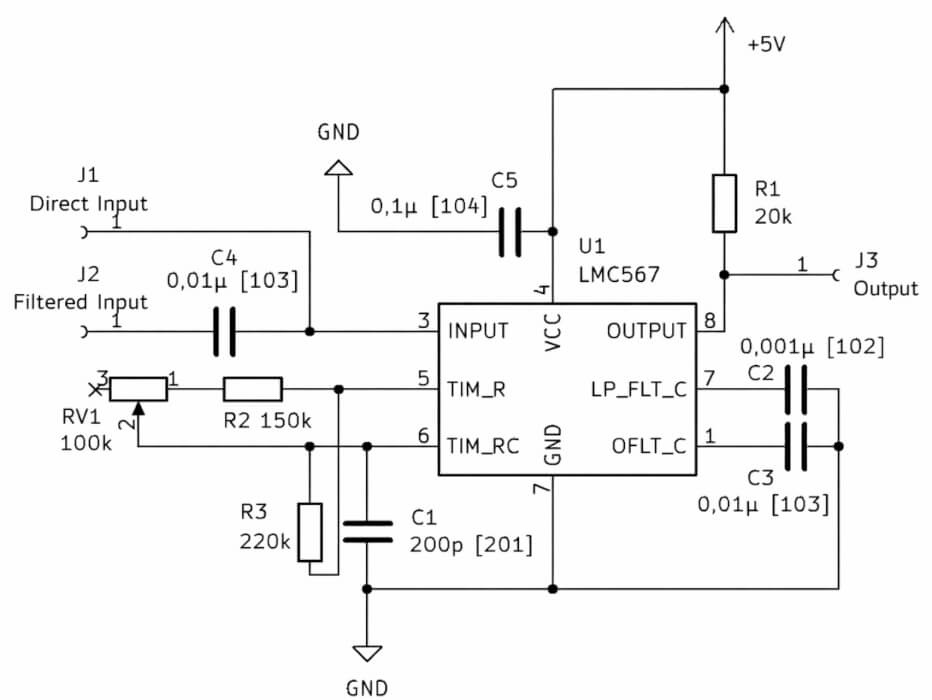
so for 175 Hz let us first check the Rt–Ct results….
For LMC567 the center frequency is:
f0 = 1 / (1.1 × Rt × Ct)
So for 175 Hz we calculate like this,
Rt × Ct = 1 / (1.1 × 175)
Rt × Ct ≈ 0.0052
Now lets pick practical values…
If Ct = 0.1 µF then Rt = 0.0052 / 0.0000001 ≈ 52 kΩ, so you can use 47 kΩ or 56 kΩ, both are fine in real life.
If Ct = 0.047 µF then Rt ≈ 110 kΩ, so 100 kΩ will work, small shifts may be ok…
The main thing however is this, for 175 Hz the Ct must be in tens or hundreds of nF, not tiny pF. If you are using 200 pF like some schematics show, then the IC will tune in kHz range, not 175 Hz, and then it will never lock properly, output may look random when frequency rises…
Also please check simple things like:.
You must have 100 nF decoupling capacitor close to Vcc and GND pins, otherwise noise will disturb it.
Input amplitude should sit around 50 to 150 mVrms, not too small not too big.
If the doorbell waveform is badly distorted then the chip may not lock cleanly, so signal quality matters.
If possible then first test using a function generator at 175 Hz sine wave, about 100 mV rms, so you can know the IC itself is fine. When it locks stable then reconnect the real doorbell signal.
If you share your exact Rt, Ct and supply voltage then I can quickly see whether tuning really matches 175 Hz or not….
Dear Mr Swagatam,
I am delighted to see that you are providing such a selfless service to anyone interested in learning circuits for different applications.
I am not a electronic-hardware professional. But I develop systems and algorithms. However, I am now faced with the following problem:
I want to detect arrival of a low frequency signal at, say, 170Hz. It lasts only for about four milliseconds. After that the signal could continue or might change. I can attempt to detect the signal within a window of four milliseconds
Can you suggest any hardware for this requirement? I shall be very thankful to you for this help
Best regards,
Rama
Thank so much you Dear S Ramaprasad, for your kind words, I appreciate it very much.
Upon investigating your requirement it seems the 4ms window is too short to detect a 170Hz frequency, because in 4ms the 170Hz cannot even complete one full cycle, so no standard filter circuit can detect this. If the frequency would have been higher or if the 4ms window would be higher then we could have tried a bandpass filter circuit….so that is the challenge, and I am not sure how to solve it.
For some reason, my 20KHz, 4Vp-p, CW tone detector is not working. Signal to Pin 3 is provided by a sig gen. I am using Ct = 0.01uF and Rt = 550 ohm. Pin 4 = 6.0 VDC and Pin 8 has a 10Kohm pullup to 6.0 VDC.
Pin 8 is always high as I sweep the frequency of Vin. I never see it lock at any freq.
What value of caps for C2 (Pin 1) and C3 (Pin 2) do you recommend for 14% bandwidth (from what equation)? I’d like to verify this as I can’t figure what else could be the issue. I value any advice you can give.
You can try the following 100kHz test circuit taken from the original datasheet of the IC
Once the basic parameters are confirmed in the above configuration, you can then tweak the relevant parts to achieve your specific results.
That’s a good way to start. Thanks for your help.
You are welcome!
Dear Mr. Swagatam,
I came across your website and it is very interesting.
Hats off to you for helping others in technical knowledge sharing and your helping nature.
I need your expertise.. I am designing a IR Proximity Sensor module with LM567 IC
with preset option (for distance adjustment).
Can you please guide me with a circuit for it?
Regards
Vasu
Chennai
Thank you Dear Vasu, you can refer to the LM567 proximity circuit under this article.
https://www.homemade-circuits.com/simple-proximity-sensor-circuit/
However, the distance for this design is only a few cms, for longer adjustable distance you may have to replace the D2 (BP104) with TSOP1738
And also make sure to adjust C2 so that frequency of the iC is set to a precise 38 kHz, otherwise the TSOP sensor will not respond.
For achieving an adjustable feature you can replace R1 with an adjustable 500 ohm preset which will help you adjust the sensitivity of the photodiode transmitter
Hello Mr. Swagatam,
Thanks for your prompt reply and guidance.
Good Luck!
Regards,
Vasu
Chennai, INDIA
Dear Swag,
I think the following paragraph is to be corrected in Application Hints no. 3
Ultrasonic controls (remote TV, etc.): Since the center frequency of LM567 is tightly locked, it may be used for detecting IR waves precisely from the given handset.
Ultrasonic controls not IR.
Thank you Ali, I have corrected the relevant paragraph.
Hi Swagatam,
I am looking for a device activating a relais when detecting a 4 kHz frequency. I learned from you that LM567 can do that. Is there somewhere also a PCB with all components on it available?
Thanks,
Hi Gustaf, yes that’s correct, you can probably try and customize the first design from this article, as per your specs:
https://www.homemade-circuits.com/tuned-infrared-ir-detector-circuit/
Olá prezado!
como posso travar o pino 8 do Lm 567 acionado, por exemplo, ele está configurado para frequência de 4 KHz, ele vai a Nível baixo, preciso que o pino 8 permaneça travado no nível baixo mesmo que a frequência aumente vários KHz
tem alguma sugestão, muito obrigado!
Hi, I think the best way to latch the load in response to the set frequency detection is to do it externally using an SCR as given in the following diagram:

dear Swagatam
i need to make fm modulation circuit with lm567. you have any circuit. please help me
thanks you!
Sorry Phung, I don’t have this circuit right now with me…
Great summery.
I was looking for a circuit to detect if any of my fire alarm units was sounding so I could automatically open the window blinds to provide escape routes, and this chip seems perfectly suitable for this job.
My alarm units beep at 3363Hz so using R=1500 Ohm, C1=220nF, C2=220nF and C3=4.7uF should do.
Will keep you posted about the result once the mems microphone module, 5V output relay and other parts have arrived and all has been assembled and tested.
Thank you, Glad you found it useful. Will wait for the updates!
how can i use this ic for making clock pulse
Please refer to this datasheet Figure:18
http://www.ti.com/lit/ds/symlink/lm567c.pdf
I alread brought a LM567 module as shows in below site
But i need a higher bandwidth. Could somebody help me to figure out what capacitor value i should change.
Im using center freq as = 815Hz
as well as 14% bandwidth i prefer
What value of a capacitor i should choose?
The formula for calculating the RC values is:
f0 ~ 1.1/RC,
where R C are the external timing resistor capacitors, f0 is the center frequency
dear Swagatam,
I was trying to buy LM567 online, but i couldn't find on some of the popular sites and I have made a list on one of the sites (of other components to buy). So I want to ask – Is there an alternative for LM567? so that i may continue with the same order from that site with that ic.
Is BA1604 the correct alternative?
Purpose is same: as the IC you used in your circuits (ir remote).
Dear Rahul,
yes you can use it, both are direct equivalents of each other.