• Skip to primary navigation
  • Skip to main content
  • Skip to primary sidebar

Homemade Circuit Projects

Get free circuit help 24/7

  • 1000+ Circuits
  • Privacy Policy
  • About Us
  • Contact
  • Disclaimer
  • Videos – Circuit Test Results
You are here: Home / Mini Projects / Simple Shadow Sensor Alarm Circuit

Simple Shadow Sensor Alarm Circuit

Last Updated on February 23, 2020 by Swagatam 7 Comments

This shadow detector circuit operates using two LDRs and effectively detects the difference between the light levels and triggers a loud audible warning siren.

In circuits which uses a single LDR (photoresist), the detection may not be as sharp as with two LDRs discussed here.Operational details of the shadow detector circuit may be studied as follows:

The key elements of this circuit are the two LDRs and the active operational amplifier, which functions as a comparator.

Circuit Operation

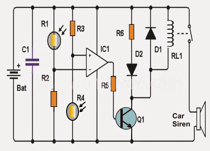
As may be seen in the diagram, the inputs of the opamp are carefully balanced using alternately positioned LDRs across the corresponding supply rails in conjunction with the respective resistors.

The two resistors may be possibly replaced with presets for getting a fine adjustment option and for ensuring an optimum balance and a perfect zero logic at the output of the opamp.

In normal light situations that is with no shadow detected (no shade) the two LDRs are able to receive the same amount of light across the sensing input of the opamp which renders a low logic level at the output of the IC.

In an event when one of the LDRs (for instance R1) experiences a shadow or less light than the other (R4), causes the voltage at the inverting input of opamp to go lower than in the non-inverting counterpart, causing the logic at the output of IC to switch to a high logic.

The above action activates transistor Q1, which in turn activates the LED and the relay. The LED allows to acquire a visual warning while the relay activates a siren device.

Preferably you may want to place a semiconductor diode (D1) in parallel with the relay, as shown in the diagram, to protect the transistor Q1 from the relay reverse EMFs.

Circuit Diagram

Things to be notes:
- The circuit is powered by 9 volt lead acid battery or any similar SMF battery.
- The LDRs should be placed with a separation of about 3cm. for an optimal response and to avoid incorrect triggering.

Parts list for the proposed shadow detector circuit

- 1 Operational amplifier: LM741 (IC1)
- 2 LDRs (photoresistor / LDR) (R1, R2)
- 1 NPN transistor 2N2222 or similar (Q1)
- 1 1N4007 diode (D1)
- 1 red LED diode (D2)
- 9 volt relay (RL1)
- Two 10K resistors (R3 and R4)
- 1 1K resistor (R5)
- 1 resistors 470 (R6)
- 1 100 nF capacitor (C1)


Previous: Cyclist’s Safety Light Circuit – Nighttime Visibility for Cyclists, Walkers, Joggers
Next: Tuned Infrared (IR) Detector Circuit

About Swagatam

I am an electronic engineer (dipIETE ), hobbyist, inventor, schematic/PCB designer, manufacturer. I am also the founder of the website: https://www.homemade-circuits.com/, where I love sharing my innovative circuit ideas and tutorials.
If you have any circuit related query, you may interact through comments, I'll be most happy to help!

You'll also like:

  • 1.  Single IC Piezo Driver Circuit – LED Warning Indicator
  • 2.  Make this Simple Refrigerator Door Open Alarm Circuit
  • 3.  How to Make a Simple 200 VA, Homemade Power Inverter Circuit – Square Wave Concept
  • 4.  Flashing LED Battery Low Indicator Circuit
  • 5.  Motion Detector Circuit using Doppler Effect
  • 6.  Simple LED Music Level Indicator Circuit

Please Subscribe (Only if you are Genuinely Interested in our Newsletters)


Reader Interactions

Comments

    Your Comments are too Valuable! But please see that they are related to the above article, and are not off-topic! Cancel reply

    Your email address will not be published. Required fields are marked *

  1. Search Related Posts for Commenting

  2. Adam says

    Please I will like a video to show me step by step in constructing Shadow Detector

    Reply
  3. adio kabiru says

    can i use ic 555 timer in place of ic lm741,is it a must i use a relay

    Reply
    • Swagatam says

      two LDRs won't be possible with a 555

      Reply
    • Swagatam says

      for a big siren, relay will be required

      Reply
  4. yasir ulhaq says

    hello sir,
    your website is awsome. iam working on a project can you please post wifi signal detector circuit

    Reply
    • Swagatam says

      thanks yasir, presently I do not have it, i'll post it if I happen to get it….

      Reply
    • yasir ulhaq says

      ok

      Reply


  5. COMMENT BOX IS MOVED AT THE TOP


Primary Sidebar

Electronic Projects Categories

  • 3-Phase Power (15)
  • 324 IC Circuits (19)
  • 4017 IC Circuits (51)
  • 4060 IC Circuits (25)
  • 555 IC Circuits (92)
  • 741 IC Circuits (18)
  • Amplifiers (49)
  • Arduino Engineering Projects (82)
  • Audio Projects (84)
  • Battery Chargers (75)
  • Car and Motorcycle (87)
  • Datasheets (45)
  • Decorative Lighting (Diwali, Christmas) (31)
  • DIY LED Projects (81)
  • Electronic Components (97)
  • Electronic Devices and Circuit Theory (35)
  • Electronics Tutorial (99)
  • Fish Aquarium (5)
  • Free Energy (34)
  • Games (2)
  • GSM Projects (9)
  • Health Related (17)
  • Heater Controllers (23)
  • Home Electrical Circuits (98)
  • Incubator Related (6)
  • Industrial Electronics (26)
  • Infrared (IR) (39)
  • Inverter Circuits (94)
  • Laser Projects (10)
  • LM317/LM338 (21)
  • LM3915 IC (24)
  • Meters and Testers (54)
  • Mini Projects (153)
  • Motor Controller (64)
  • MPPT (7)
  • Oscillator Circuits (12)
  • PIR (Passive Infrared) (8)
  • Power Electronics (33)
  • Power Supply Circuits (66)
  • Radio Circuits (9)
  • Remote Control (46)
  • Security and Alarm (56)
  • Sensors and Detectors (116)
  • SG3525 IC (5)
  • Simple Circuits (72)
  • SMPS (30)
  • Solar Controllers (60)
  • Timer and Delay Relay (51)
  • TL494 IC (5)
  • Transformerless Power Supply (8)
  • Transmitter Circuits (38)
  • Ultrasonic Projects (12)
  • Water Level Controller (45)

Follow Homemade Circuits

Facebook
Twitter
YouTube
Instagram
My Facebook-Page
Quora

Feeds

Post RSS
Comment RSS

Circuit Calculators

  • AWG to Millimeter Converter
  • Battery Back up Time Calculator
  • Capacitance Reactance Calculator
  • IC 555 Astable Calculator
  • IC 555 Monostable Calculator
  • Inductance Calculator
  • LC Resonance Calculator
  • LM317, LM338, LM396 Calculator
  • Ohm’s Law Calculator
  • Phase Angle Phase Shift Calculator
  • Power Factor (PF) Calculator
  • Reactance Calculator
  • Small Signal Transistor(BJT) and Diode Quick Datasheet
  • Transistor Astable Calculator
  • Transistor base Resistor Calculator
  • Voltage Divider Calculator
  • Wire Current Calculator
  • Zener Diode Calculator

© 2021 · Swagatam Innovations