In this article I have explained a few useful yet easy to build home automation circuits which will help the user to create automatic electronic systems at home.
What is Home Automation
Home automation basically means converting many of the manually operated home electrical devices into automatically operated devices, through electronics.
Today's real home automation systems involve the use of mobile app to control many of the home electrical systems from any place inside home or even outside home.
However, in this article we won't be discussing such complex app controlled systems because these are difficult to design and configure.
Instead, we are going to check out simple to build electronic devices for creating a few automatic systems which can make the life of the user easier and convenient.
The main idea of these circuits is to bring more comfort and security in the life of the user.
Which Circuits will be Discussed Here?
The circuits which will be discussed here are as follows:
- Remote control for AC electrical loads
- Automatic porch light and garden light circuit
- PIR controlled burglar alarm circuit
- PIR controlled automatic bathroom, staircase light circuit.
- Mobile app controlled simple automatic door lock.
The above mentioned units can be further customized for making other interesting home automation systems.
Let's discuss the above circuits one by one.
Remote Control for 220V Electrical Load
When an electrical load such as light or fan is configured with this circuit, it can be controlled remotely using any ordinary remote control.
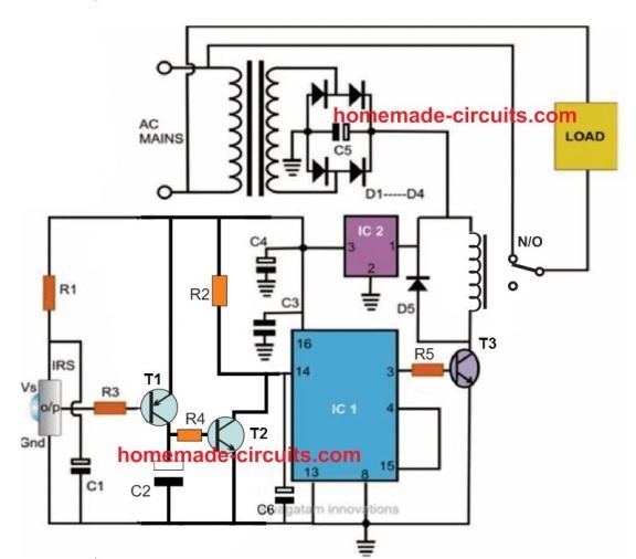
Complete parts list and explanation is given in this article;
The remote control handset can be any IR remote control unit such as a TV remote control.
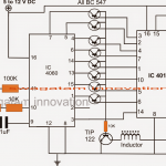
The sensor stage is built using IR sensor TSOP1738 IC. This sensor is configured with a flip flop stage built using the C 4017.
When this sensor is triggered with a TV remote, the output from the sensor activates the 4017 cock input.
The alternating clock pulses generated by the TSOP1738 sensor causes the IC 4017 to toggle its output in a flip flop manner.
This flip flop output from the IC 4017 toggles a connected relay ON/OFF.
Any electrical load connected with relay can be now toggled ON/OFF through the alternate pressing of the TV remote button.
This simple remote controlled relay circuit can be used to automate the ON/OFF switching of any home appliance.
Automatic Porch Light
The automatic porch light is another electronic circuit which can be use to automate the switching of the porch lamp.
For the parts list and the complete explanation please refer to this article.
It is basically an LDR based circuit which senses the ambient light conditions and switches OFF the lamp at day break and switches ON after evening.
The porch light can be also be used to control any other outdoor lamp such as a garden lamp.
The functioning of the automatic day night porch lamp is simple.
As long as there's sufficient day light falling on the LDR, the transistor remains switched ON. This keeps the relay also switched ON. However, in this condition the lamp being connected with the N/C keeps the lamp switched OFF.
When the day light diminishes below a certain threshold, the LDR resistance increases causing the transistor relay to switch OFF. The relay now changes position to the N/C contacts, switching ON the lamp.
PIR Burglar Alarm Circuit
The next home automation circuit is a PIR controlled simple burglar alarm circuit.
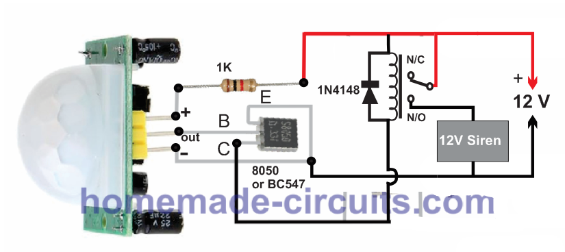
The circuit can be positioned at the entrance of the house, on a window or in any area which needs to be monitored against potential intruders.
The PIR is a device which is designed to detect the IR heat signals from a living thing such as a human body.
Whenever there's any human intervention within the detection range of the PIR, a tiny pulse is released by the PIR.
This pulse is then used to switch ON a transistor relay circuit which in turn triggers ON a connected alarm or a siren.
The alarm sounds and alerts the home owner regarding the presence of a human intruder within the restricted area.
PIR Controlled Bathroom Lamp or Staircase Lamp
The same PIR circuit explained above can be effectively used for controlling bathroom light, staircase, lamp or corridor lamps.
This will fully automate the area where the PIR circuit is installed.
For example, if the PIR circuit is installed in the bathroom then the switching of the bathroom lamp will become fully automatic. The lamp will remain switched ON only as long the user is present in the bathroom, and the lamp will be switched OFF automatically when the user leaves the bathroom.
The same functioning can be expected if the PIR circuit is installed in the staircase. The staircase lamp will be automatically switched ON whenever a user wants to use the staircase. The lamp will remain turned off as long as the staircase is vacant and not being used.
This system can keep the lamps of the above areas switched OFF while it is not being used, saving electricity and increasing the lamp life.
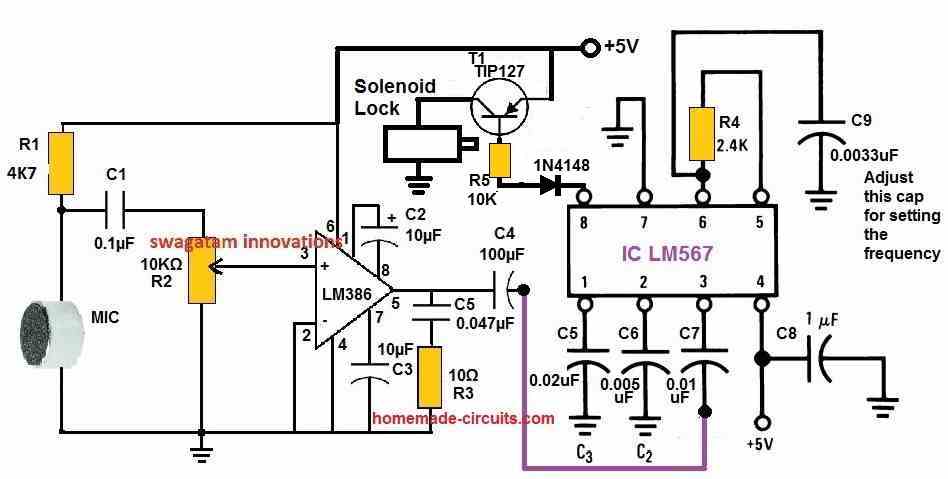
Mobile app Controlled Simple Automatic Door Lock
In this home automation circuit, a simple electronic door lock is operated through a sound frequency generated from a mobile app.
The mobile app a sound frequency generator set to generate a specific sound frequency.
The automatic door lock has a frequency detector which detects this specific frequency for around 3 seconds.
After 3 seconds of detection the door lock pulls back the solenoid shaft, releasing and opening the door lock.
This lock is fool-proof because it detects and opens the lock only when a specific frequency is detected. It will not respond to any other unknown frequency.
The 3 second delay makes sure that no randomly adjusted frequency would work to break the code and the lock.
This delay feature is not shown in the diagram. It will need to be included using a BJT stage with pin#8 of the LM567 IC.
The heart of the circuit is the LM567 tone decoder which implements the main frequency detecting function.
The specific frequency output from the mobile phone is introduced close to the MIC. This is done by activating the mobile app frequency generator and bringing the mobile speaker close to the MIC of the circuit.
The frequency detected by the MIC is amplified by the LM386 IC and is fed to the frequency detection input of the IC LM567.
The LM567 IC detects and checks the frequency, if it matches its internal set frequency then it switches its pin#8 low.
As soon as pin#8 turns low it drives the TIP127 transistor and the attached solenoid is turned ON.
The solenoid lock now opens, so that the user can open the door.
The detection frequency of the LM567 IC can be calculated using the following formula:
fo = 1 / (1.1 × R4 × C9)
Questions & Answers
For Mobile app Controlled Simple Automatic Door Lock, will any mobile app sound frequency generator work?
Yes, any mobile app sound generator will work, as long as it generates the specified frequency accurately.