An alcohol detector is a sensitive device which is able to detect the presence of alcohol molecules or any similar volatile inflammable element in the air and convert it into equivalent level of electrical output.
The simple alcohol detector circuit discussed here will accurately sense the emanation of alcohol gas from a selected source, such as from the mouth of a drunkard, when used as a breathalyzer. It's cheap and a useful device which can be used by all authorized personnel such as a cops or traffic police for nabbing drunken drivers or miscreants.
Initially I thought of using an Arduino for the experiment, I uploaded the code in my Arduino Uno, but then realized it was simply not necessary since it could be effectively implemented with a simple LM3915 circuit, and therefore dropped the Arduino idea and proceeded with the design as described below.
Main Modules
The main circuit modules required for the proposed alcohol tester circuit are an LM3915 based LED bar graph circuit and an MQ-3 sensor module.
For my experiment I purchased the entire MQ module, but actually only the sensor is enough, and would do the job efficiently.
Regarding MQ-3 Module
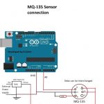
A standard MQ-3 Alcohol Sensor module will basically consist of an orange MQ-3 sensor, and an LM393 based comparator circuit as shown below.
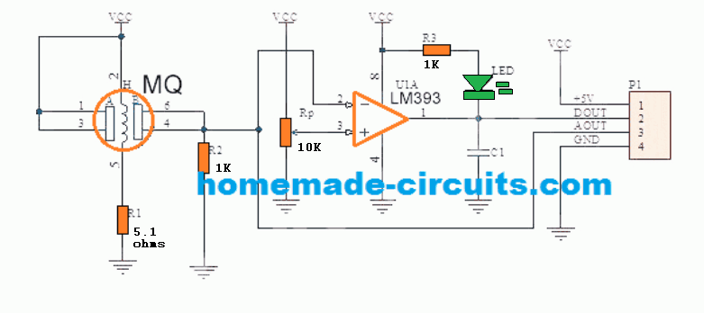
The operation of the module is pretty simple. When the sensor is brought near an alcohol or ethanol source, the voltage level at the input pin#2 of the comparator goes above the reference pin#3, causing the output to go low. The green LED Illuminates to confirm the results.
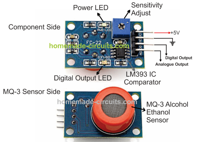
Module Pinouts
The following image elaborately shows the specs and the working details of a standard sensor module pinouts:
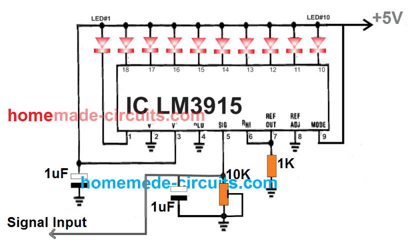
LM3915 LED Bar Graph Indicator
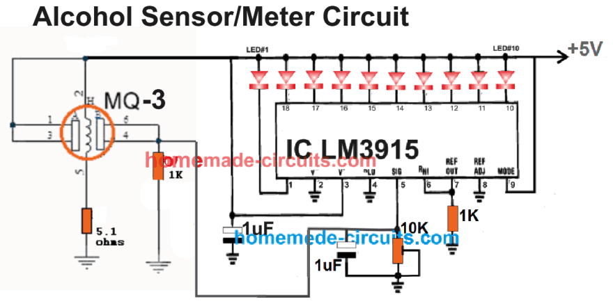
In the present design we use the popular LM3915 bar graph LED circuit for detecting the alcohol level from the MQ-3 sensor. The basic signal detector circuit diagram can be seen below:
Now let's see how the MQ-3 sensor could be integrated with the above LED indicator circuit for implementing the proposed alcohol meter circuit.
How the Circuit Works
The working of the alcohol/ethanol detector meter is very straightforward.
When the MQ-3 sensor detects the presence of alcohol molecules, the voltage at its output pin begins rising.
Depending on the concentration of the alcohol or ethanol, the output voltage keeps rising and stabilizes at the highest detected level.
This rise in potential is captured by the input pin#5 of the LM3915 circuit and is appropriately interpreted by sequentially illuminating the attached 10 LED bar-graph meter.
Any Initial Setups
No setting up procedures are required for the sensor except the 10K preset in the LM3915 circuit.
Without the sensor connected, adjust the preset such that only the green LED illuminates, which will be indicating zero level of alcohol in the finalized circuit.
The Entire Module or Just the Sensor
If you are wondering whether the entire MQ-3 module is required or simply the sensor block can be used, the answer is either will do.
However the entire module being costlier, just the orange colored MQ sensor is all that could be needed for the purpose. The pinout details of the sensor can be visualized below:
How to Identify the MQ-3 pins
If you are having difficulty in identifying the pinouts of a naked MQ-3 sensor, the following image will provide a clear idea regarding its details.

If you have any further questions please feel free to ask them through the comment box.
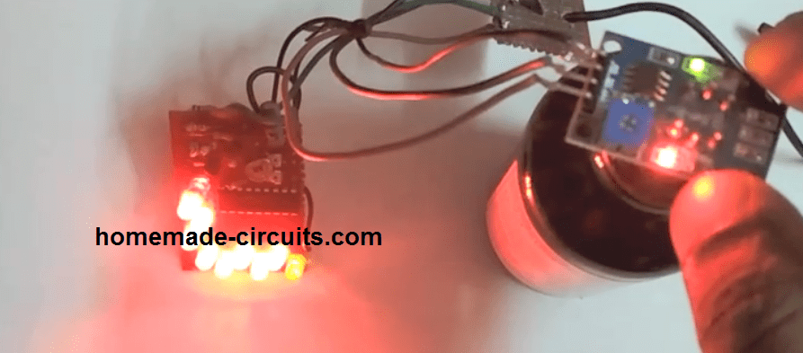
Video Demonstration

Questions & Answers
Detect alcohol in your sleeping teen’s room. Set off alarm and text your phone
Hehehe
How low can ppm level be set?
Haha, that is a funny idea! The MQ-3 sensor can go down to about 25 ppm… but honestly, this plan will not work for a whole bedroom. When someone is sleeping, then tiny bit of alcohol from their breath gets mixed into the huge room air instantly. That dilutes it way too much causing the level much lower than what the sensor can actually notice. For the alarm to work, your teen would need to wake up and blow directly into the sensor from an inch away like a police breathalyzer. Plus things like body spray, deodorant, or perfumemight trick the sensor and trigger a fake alarm anyway!
Thank you, sir! This document is very important about LM393 IC comparator.
Thank you Silanu, Glad you found the post helpful.
Thanks Swagtam
Kindly advice on how to connect the module output to the LM3915 circuit as vcc – 5v + , gnd – through 5 ohms resistor and some clarification on where the DO & AO are connected to.
Hervinder, first use a common +5V line and the negative line for both, the module and the lm3915 circuit, then connect the analogue output from the module with the “signal input” line of the LM3915. DO is not used, only AO is used as the input for the LM3915 circuit.
Hi Swagtam
Trying out this project and using the standard sensor module. Just some clarification on pin DO # 2 & AO #3 and connection to the circuit
Hi Hervinder, Dout is the digital output from the opamp, which will be either high or low depending on the preset setting and gas level.
Aout is the analogue output directly from the sensor, which will produce a slow exponential rising voltage depending on the gas concentration level.
Guys, what is the value of capacitance in MQ -3 module, do I have to decide it by myself or there might be some standards?
Hi there, which capacitance are you referring to??
I am eswarabalan from tamilnadu how much rate for new arduino code
Rs.10/- per line of code!
I think you guys are doing a great job with the circuits that you send out I really think it is great.[ Thanks] just keep up the good work I hope that everyone on eBay likes the work you do as well as I do
Glad you liked my work, Thank you for sharing your views!