In this post I have explained how a neat little self regulating automatic battery charger circuit can be made using just two inexpensive transistors.
This circuit will automatically regulate the charging supply to the battery depending on its charge level, by switching the input supply ON and OFF periodically.
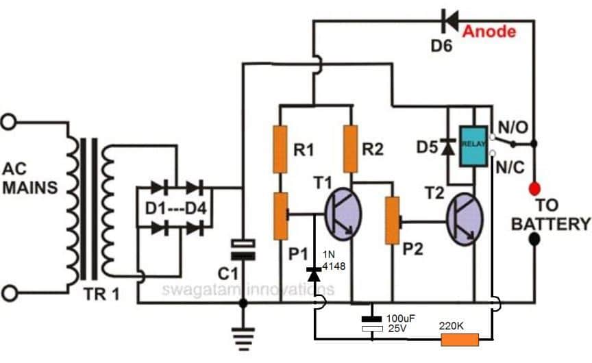
How it Works
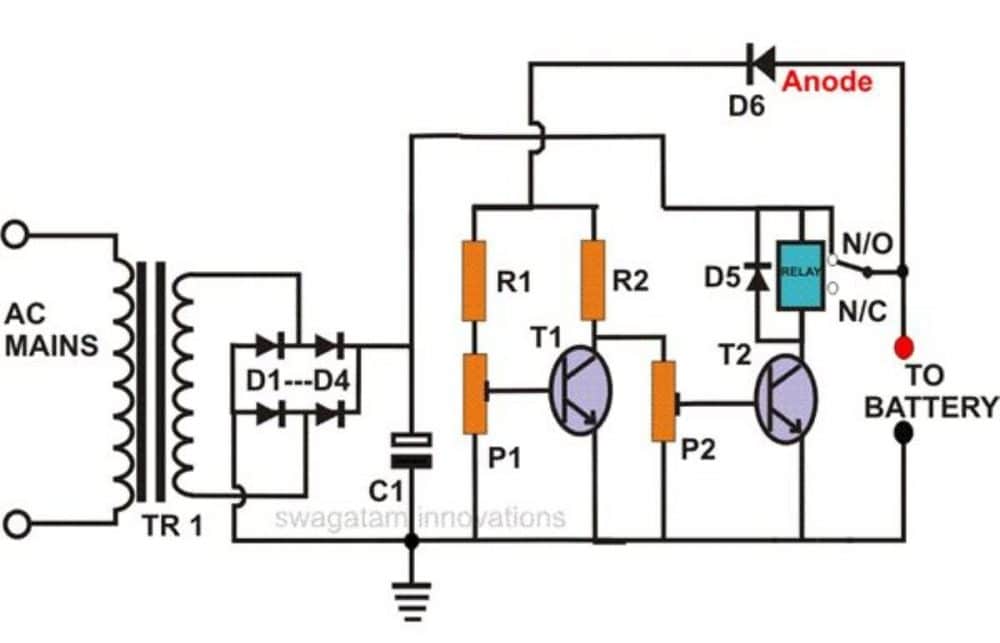
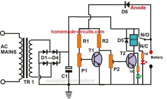
As can be seen in the diagram, this auto-regulating battery charger circuit utilizes just two transistors for detecting the charging thresholds, and cuts off the process as soon as these limits are detected.
Using two transistor actually makes the design hugely sensitive compared to a single transistor charger circuit.
The indicated preset is set in such a way that the T1 is just able to conduct at the specified full charge threshold of the battery.
When this happens T2 begins switching OFF, and ultimately at a point it is unable to sustain the relay conduction and switches OFF the relay, which in turn cuts of the input charging source with the connected battery.
Conversely, when the battery voltage begins dropping, T1 gradually deprived of its adequate conduction voltage level, and ultimately it ceases to conduct, which quickly prompts T2 to initiate its conduction and trigger the relay into action,
The relay now reconnects the charging input supply with the battery, and restores the charging process until it yet again reaches the full charge threshold, when the regulating cycle repeats itself.
How to Sep Up the Circuit
Setting up this battery charger circuit for automatic regulation is very simple and may be done in the following way:
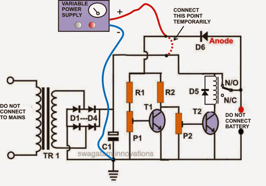
- Initially, do not connect the fixed transformer power supply; instead connect a 0-24V, variable supply voltage to the circuit.
- Remove the anode of D6 from the relay contact and connect it to the positive of the power supply.
- Keep both the presets somewhere at the center position.
- Switch ON the power and adjust the voltage to 11.5 volts or lower.
- Adjust P2, so that the relay just activates.
- Now increase the volts to about 13.5 volts, and adjust P1 so that the relay just deactivates.
The setting procedure of the circuit is now complete.
Check the whole procedure by continuously varying the voltage up and down.
You may now remove the variable power supply and connect the fixed transformer, bridge power supply to it.
DON’T FORGET TO RECONNECT THE ANODE OF D6 BACK TO THE RELAY CONTACT OR THE BATTERY POSITIVE.
The battery connected to this circuit will be charged only as long as its voltage is in between the above "window" level.
If the battery voltage crosses the above "window", the relay will trip and stop the battery from charging.
Parts List
- R1, R2 = 10K = 2
- P1, P2 = 10K PRESET = 2
- T1, T2 = BC 547B = 2
- C1 = 2200uF/25V = 1
- C2 = 47uF/25V (Please connect this capacitor across the relay coil) = 1
- D1---D4 = 1N5408 = 4
- D5, D6 = 1N4007 = 2
- RELAY = 12 VOLT, SPDT = 1
- TRANSFORMER = 1, (AS PER THE CONNECTED BATTERY AH (DIVIDE BY 5)
The following diagram shows the instructions which needs to be followed while setting-up the circuit with the desired cut-of thresholds, using a variable power supply unit:
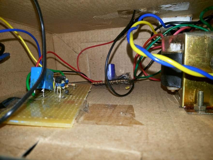
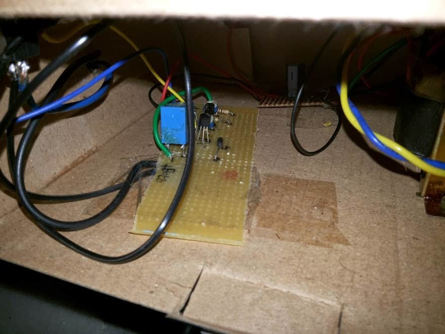
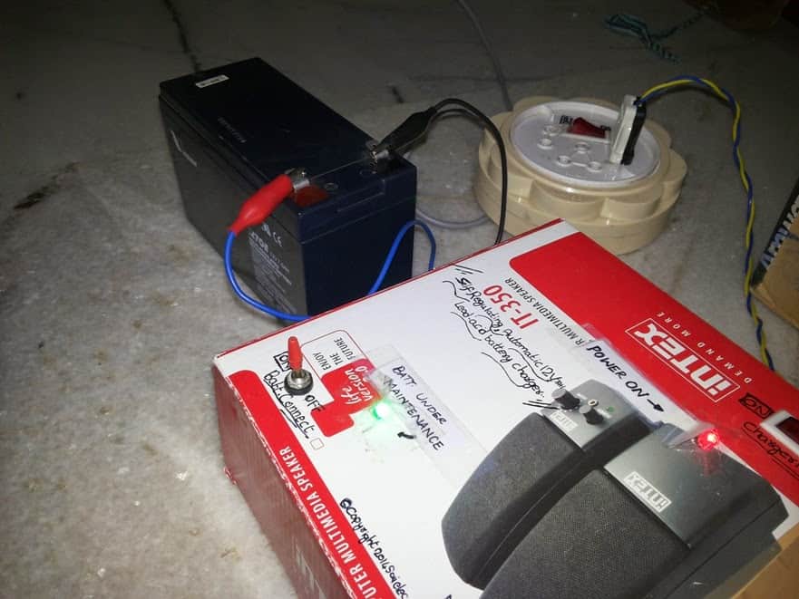
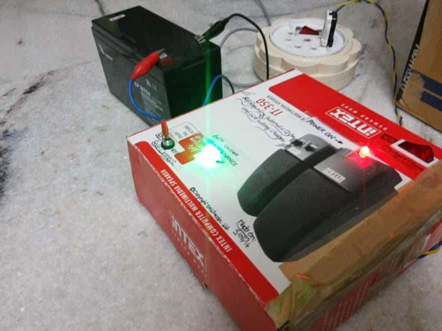
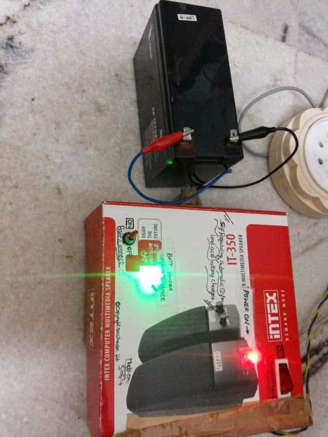
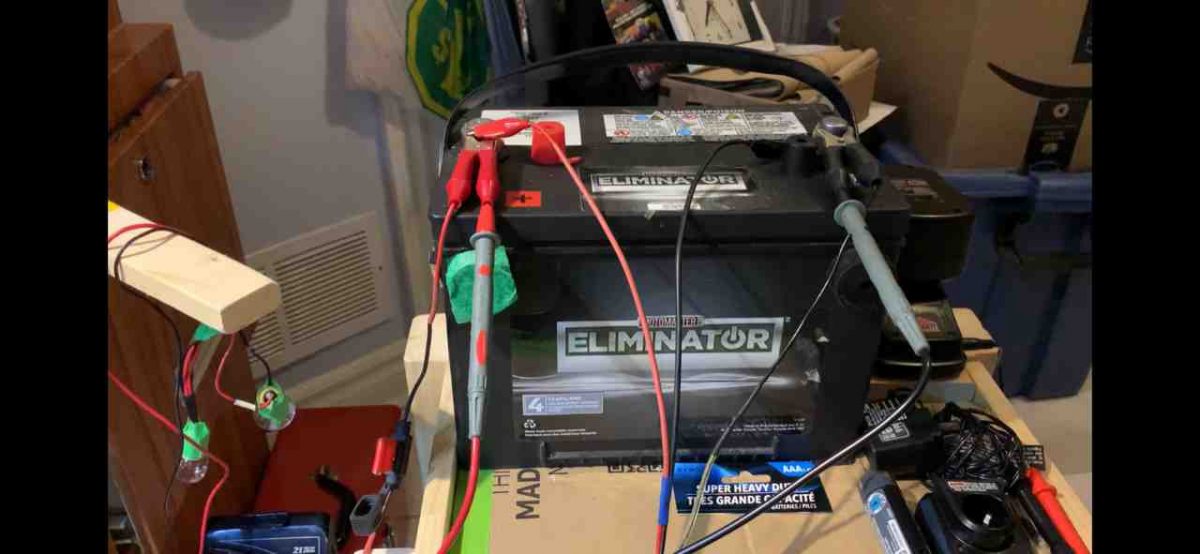
The above self-regulating battery charger circuit was successfully built and tested by Mr. Sai Srinivas, who is just a school kid but nevertheless has an immense interest in the field of electronics.
The following images were sent by him which displays his talent and intense dedication in the field.
For One Shot Operation
If you want the above circuit to lock itself into a permanent cut off position when the battery is fully charged, then you may modify the design as shown below:
Note: To ensure the relay does not latch itself quickly on power switch ON, always connect the discharged battery first across the shown terminals and then switch ON the input power.
In order to indicate the charging status of the battery, we can add a couple of LEDs to the above design, as shown below.
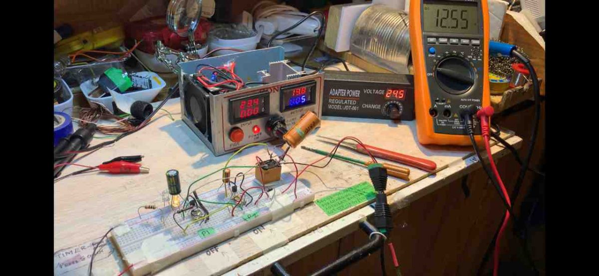
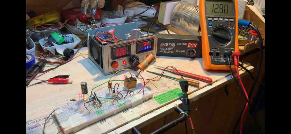
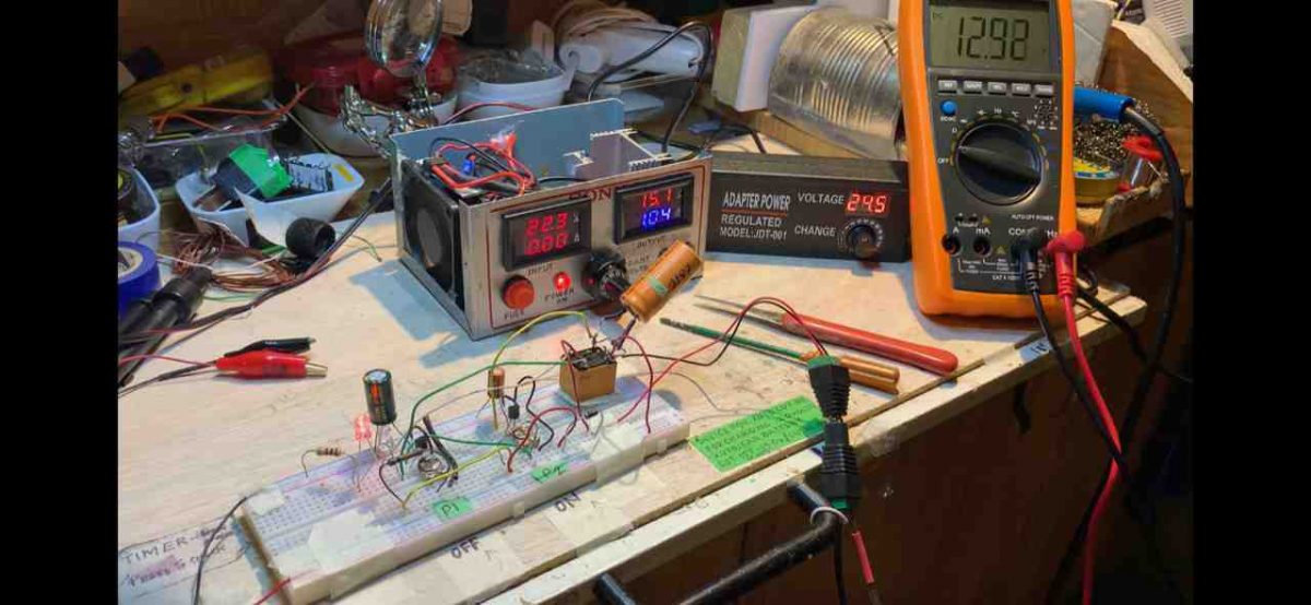
The above circuit was also successfully built and tested by one of the dedicated electronic enthusiasts from this blog. The following pictures verify the results:
Warning: Make sure to test the preset setting thoroughly before you leave this application unattended. And be sure to use only 14V as the input supply for a 12V battery.
Formulas and Calculations
Full-Charge Cutoff Voltage
The voltage at which charging stops is calculated as:
Vcutoff = VBE(T1) + (P1 / (R1 + P1)) * Vsupply
For example:
Full-charge voltage (target) = 13.8 V
VBE(T1) = 0.7 V (for silicon transistors)
Vsupply = 15 V (after rectification and, filtering)
To achieve a cutoff of 13.8 V you can set the divider network:
13.8 = 0.7 + (P1 / (R1 + P1)) * 15
Rearranging for P1 / (R1 + P1):
P1 / (R1 + P1) = (13.8 - 0.7) / 15 = 13.1 / 15 ≈ 0.873
Choose R1 = 1 kΩ.
Then: P1 = 0.873 * (R1 + P1)
P1 = 0.873 * (1000 + P1)
P1 ≈ 687 / 0.127 = ~6.87 kΩ
Set P1 to approximately 6.8 kΩ.
Reactivation Voltage
The voltage at which charging restarts is calculated as:
Vreactivation = VBE(T2) + (P2 / (R2 + P2)) * Vsupply
For example:
Reactivation voltage = 12.6 V
VBE(T2) = 0.7 V (same assumption as above)
Vsupply = 15 V
To achieve a reactivation voltage of 12.6 V:
12.6 = 0.7 + (P2 / (R2 + P2)) * 15
Rearranging for P2 / (R2 + P2):
P2 / (R2 + P2) = (12.6 - 0.7) / 15 = 11.9 / 15 ≈ 0.793
Choose R2 = 1 kΩ.
Then: P2 = 0.793 * (R2 + P2)
P2 = 0.793 * (1000 + P2)
P2 ≈ 793 / 0.207 = ~3.83 kΩ
Set P2 to approximately 3.9 kΩ.
Relay Activation Current
The current needed to activate the relay is:
Irelay = Vcoil / Rcoil
For example:
Vcoil = 12 V (relay coil voltage)
Rcoil = 400 Ω (typical relay coil resistance)
Irelay = 12 / 400 = 0.03 A (30 mA)
Filter Capacitor Value
The filter capacitor smooths the DC and is calculated as:
C1 = Iload / (2 * f * DeltaV)
For example:
Iload = 1 A (charging current + circuit consumption)
f = 50 Hz (mains frequency)
DeltaV = 2 V (acceptable ripple voltage)
C1 = 1 / (2 * 50 * 2) = 1 / 200 = 0.005 F = 5000 µF
Choose C1 = 4700 µF or 6800 µF... for sufficient filtering.
Hysteresis Voltage
The hysteresis prevents frequent relay switching and is calculated as:
V_hysteresis = V_cutoff - V_reactivation
For example:
V_cutoff = 13.8 V
V_reactivation = 12.6 V
V_hysteresis = 13.8 - 12.6 = 1.2 V





Questions & Answers
yes, that's why I have attributed the word "self regulating" to it, meaning as soon as the battery voltage drops at a certain value the circuit will again start the charging process and never allow the battery voltage to fall below a specified lower level.
Hello sir,
Can i use this circuit for my UPS battery charge control. It charges at 10amp but there is a problem in the UPS built-in charge controller and it does not trip automatically when the battery is fully charged. I'm asking if i can install this circuit in this system.
Regards
Hello Muhammad,
Yes you can use it, but you will have adjust the presets very carefully for getting the desired cut-offs.
Swagatam, i have a 1000VA IPS that uses 24v, 14AH sealed lead acid battery. It was brought for backup computer. Is it possible now to use the IPS with a 24v, 70AH battery for longer backup as I want to drive it a fan and 2 light?
Pls suggest me what can i do at this time.
Hi Debashish, yes it's possible, as long as the voltage is not altered or exceeded beyond the specified limit AH won't matter, it will only help to provide higher backup time.
yes it will work
thanks! presently i do not have 0-1000 degree circuit, if i get i'll surely post it for you.
@Swagatam Majumdar,
good work…
my question is this….
will this circuit diagram cut-off the voltage when the battery is fully charge?
thks. hope to read your reply soon.
thanks! Yes the relay will cut-off as soon as the voltage reaches the set upper threshold and stop further charging of the battery
Hi swagatam
Thanks to your post i make this circuit and its work…how can i add 2 led bulb for charge monitoring..i plan to place 1 red led for charging status and 1 green led for full charge status..how can i connect this to the circuit?
Hi Flhex,
Thanks, however here only one LED would work effectively across D5.
Connect it with a 10k series resistor, it will indicate "battery full and disconnected", another "power ON" indicator LED can be added directly across the positive/negative line with a 10k series resistor.
Hi sir,
I want made 12v & 24v single transformer. Variable current rating. How I design cut off circuit. Please help me.
Thank you
Hi Suresh,
Try the first circuit from this link:
https://www.homemade-circuits.com/2012/07/make-6v-4ah-automatic-battery-charger.html
Thank you sir
hello
pls i dont understand that relay part. NO and COMMON are nit joined inside relay but you joined them in ur diagram. i understand that NC is not connected. pls clarify the connection of NO and COMMON. thanks for your response!
The diagram shows the relay in activated mode while charging the battery, therefore the N/O is connected to pole, when deactivated it will connect with N/C
Hello Swagatam, please can dis circuit output voltage be regulated so as to charge the battery at thesame rate as it is discharged?
Using d appropriate transformer amperage how long will it take to charge a 12v 100amps battery?
Please can this circuit output voltage be regulated so as to charge the battery at thesaurus rate as It's discharging?
Hello Mega blessing,
yes it can be done simply by using an appropriately rated transformer.
for any lead acid battery the ideal charging time is around 10 to 14 hours.
Hello swagatam, i like ur circuit,easy to understand, i want to charge 3v battery(2×1.5v) can i change D5,D6 to 3v zener diode,to trigger the relay.hope u understand
hello mohammad,
all the diodes shown in the diagram are 1N4007, these are not zener diodes but ordinary rectifier diodes, you can use them as given.
dear sir 1 want to charge 12v45ah battery i have 5A20v ups transformer. this will work?
Dear Jayanth, use a LM338 IC based charger to drop the 20V to 14V for charging your battery.
I have published many LM338 IC chargers, you can search them through the search box at the top
ok sir,,,,How to Make an Automatic 12 volt Battery Charger Circuit Using IC LM 338
im going to make above one. please answer my question on that comment forum.
sir, for c1, can i use a 1000v,25uf capacitor? and for c2, can i use a 100uf 25v capacitor? and for d1—–d4, can i use 1n4007 diodes, sir? please tell me sir….
yes will do…
sir, i want to use this circuit with a 12v 7ah battery. can i use a 12v, 1amp transformer, sir?
yes, it's fine, you can proceed.
sir, i assembled the circuit and it switches on relay when i connect power supply. and when i adjust the presets, the relay stays in on position only(in both cases i.e., in adjusting cut off and adjusting switch on of relay). please tell me whether i should connect power supply including bridge or directly to capacitor? also please tell me if i should connect battery while setting the circuit, sir? please help me…
thanks.
Battery should not be connected while setting up the circuit.
you must use a variable power supply for setting-up the circuit as instructed in the article.
I'll update the diagram with the required information shortly.
sir, please tell me where i should connect variable power supply when setting up the preset resistors and the circuit before connecting the battery and fixed transformer? thank you for your help…….
sir, thank you very much for your help. im sure this would help others also……by the way, this circuit WORKED on my breadboard..thank you again…….
you are welcome!
Dear sir, ive been using this circuit for more than a month now….works great I sent the photos of circuit to your mail(homemade circuits@gmail.com)……
Regards
Ss.
That's great SS, thank you, I'll check them out soon.
Sir, could you please help me in designing an automatic 24 V battery charger circuit having the following spec.
– it should be capable of charging a 24 V 80 Ah battery bank
– higher voltage cut off and lower voltage turn on facilities
I have a 300 W inverter transformer with me which is a 230 V / 15-0-15 type… So the primary winding can handle a maximum current of 20 A…….. So is it possible to use the primary terminals of this transformer ( end taps excluding the mid one,showing a voltage of 30V total ) to charge this battery ?????
Arun you can try the second circuit from the following article:
https://www.homemade-circuits.com/2011/12/how-to-make-simple-low-battery-voltage.html
You can use the 30V/20Amp transformer as the input, but don't use a filter capacitor, just connect a single rectifier diode for rectification, and use it as the input with the above linked circuit.
Is the second schematic (testing setup) accurate?
It seems to conflict with text as to the connections around D6.
The text indicates the +VDC to be connected to the anode of D6 but the schematic shows it connected to the cathode and the coil and NO connection of the relay.
Actually D6 is not crucial and could be removed, I placed it initially just for a psychological comfort, practically it serves no purpose.
Therefore the circuit actually becomes very simple now, remove the entire D6 link and connect the R1/R2 junction with the positive line.
The setting up procedure may be done by supplying the external variable voltages across the positive/negative lines of the circuit, without any battery connected and also without the mains input to the circuit transformer.
Thanks for the info.
I have completed the circuit without a D6, but used PN2222 NPN transistors instead, as I had them here and their characteristics are similar to the 547B ones.
I can setup the charge on cycle, but I cannot get the off adjust to work at all. The relay stays locked on through the entire range of P1. In fact once the relay engages, the only way to get it to go off is by removing the power. Once power is restored, it immediately engages again. If I drop P2 back to center, it will stay off until I adjust it as per spec.
Any thoughts on this?
Additional info:
I found one of the resistors I used was way out of tolerance, down to about 700 ohms or so.
I replaced it and the circuit seems to work as stated, but I am having a lot of diffiuculties getting the levels dialed in as both affect the other. Adjust one to the proper level will bring the opposing one off of it's level and vice versa.
It seems to me the critical one to get accurate is the off limit, as this one is the key to stop over charging.
I found the point was so finely tuned that just touching the pots would cause them to flip the relay state. Maybe multiturn pots would make setup easier.
I also found that the lower setting has little effect. When the upper one is set at say 13.8 volts (normal for a fully charge 12V lead acid cell), any voltage below 13.3 will cause the relay to engage and start the charge cycle again. The voltage would never get down to 11.5 volts, even though that level had been set first.
I gave up tweaking after 45 minutes, as it is just too sensitive to get dialed in properly.
I agree with you, setting up the lower threshold could be a bit difficult with this circuit…you could probably try one simple modification for achieving the desired lower threshold activation to a reasonably accurate extent.
Try adding a high value resistor from N/C of the relay to the base of T1….the value of the resistor will need to be experimented, may be a 1M could be the starting value and lowered down until the right one is found.
The mod will basically add a bit of hysteresis to the design which is actually missing in the here and needs to be added for the intended results.
you can also add a capacitor in parallel to the relay coil to stop the relay from chattering at the thresholds
I have the 47uf cap already in place.
I will try the resistor mod when I get back to bench later on, and let you know hos it goes.
sure, thanks!
It ended up being an 820k resistor that gave the best results.
It is still very sensitive to tweak, but it got easy enough to tune it in quite close to were I wanted it to be.
There is still a fair amount of variance in the cut in voltage, but the cut out is quite stable.
Thanks for the help!
That's great! Thanks for confirming it, this update will be quite helpful for the other readers.
I just noticed something about the circuit. When you said to remove D6 and connect the R1/R2 to +, was that correct?
It seems it will not detect the battery state unless the relay is enaged, so the charger will never start when hooked up to an actual battery.
I think the R1/R2 should be connected to the COM (Armature) contact of the relay that is connected to the battery.
Oh yes, I seemed to have missed it completely.
R1/R2 should be connected with the relay pole, as rightly indicated by you.
Hi M Majumdar,
Please could you help me !!! I can not make the setting of your circuit. I don't understand what you means with " connect this point temporarily" on the second drawing? Is there 2 points for the positive input for the variable supply? The line in dot ???
And where do you set the resistor of 820K in the circuit?
Thanks
Hi Willy,
" connect this point temporarily" means join those points together with a wire link (wire link shown as red dotted line)
Join 820 k resistor from the "normally closed" contact of the relay to the base of T1