The 4 simple car voltage current regulator circuits I have explained below is created as a immediate alternative to any standard regulator and, although developed principally for a dynamo it will function equally effectively with an alternator.
If the functioning of a traditional car alternator voltage regulator is analyzed, we find it amazing that these kinds of regulators is often as trusted as they are.
While most contemporary cars are furnished with solid-state voltage regulators to regulate the voltage and current output from the alternator, you may still find countless earlier cars installed with electromechanical type of voltage regulators that happen to be potentially unreliable.
How Electro-Mechanical Car Regulator Work
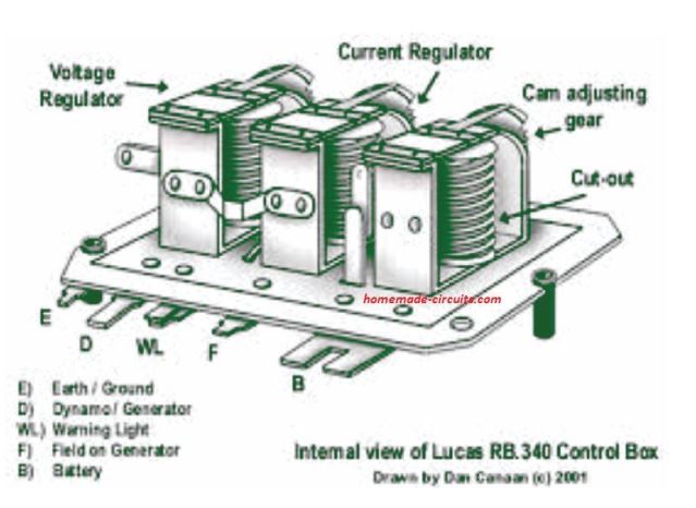
The standard functioning of a electro-mechanical car alternator voltage regulator can be as I have explained below:
Once the engine is in the idling mode the dynamo starts getting a field current through the ignition warning lamp.
In this position the dynamo armature remains unattached with the battery since its output is smaller compared to battery voltage, and the battery starts discharging through it.
As the speed of the engine begins increasing, the output voltage of the dynamo also begins rising. As soon as it surpasses the battery voltage a relay is switched ON, connecting the dynamo armature with the battery.
This initiates the charging of the battery. In case the dynamo output goes up even more an additional relay is activated at around 14.5 volts which cuts off the dynamo field winding.
The field current decays while the output voltage begins dropping right up until this relay deactivates. The relay at this point consistently switches ON/OFF repeatedly, sustaining the dynamo output at 14.5 V.
This action safeguards the battery from overcharging.
There's also a 3rd relay containing its coil winding in series with the dynamo output, through which the entire dynamo output current passes.
Once the safe output current of the dynamo gets dangerously high, may be due to over discharged battery, this winding activates the relay. This relay now detaches the field winding of the dynamo.
The function ensures that just the fundamental theory, and the specific circuit of the proposed car voltage current regulator may have different specs depending on a specific car dimensions.
1) Using Power Transistors
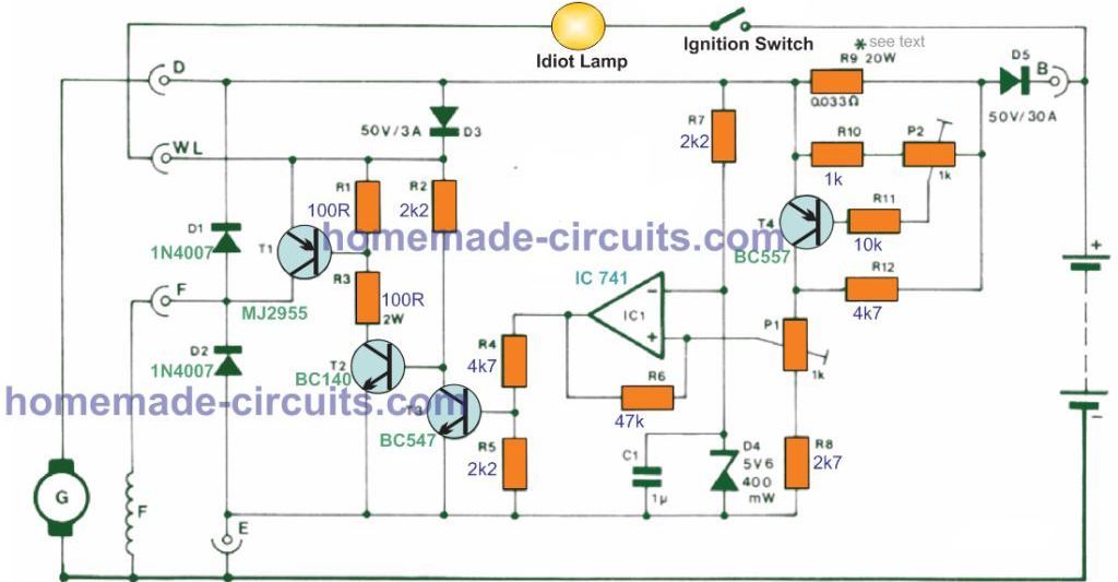
In the indicated design the cut-out relay is substituted by D5, which gets reverse-biased as soon as the dynamo output drops below the battery voltage.
The battery as a result is unable to discharge into the dynamo. If the ignition is started up the dynamo field winding gets current through the tell-tale light and T1.
Diode D3 is incorporated to avoid current becoming drawn from the field coil due to the reduced armature resistance of the alternator. As the speed of the engine increases the output from the dynamo proportionately rises, and starts delivering its own field current by means of D3 and T1.
As the cathode side voltage of D3 goes up the warning light gradually dims until it fades off.
When the dynamo output reaches to around 13-14 V the battery begins charging again. IC1 works like a a voltage comparator which tracks the dynamo output voltage.
As the dynamo output voltage increases the voltage on the op amp inverting input is at first greater than at the non-inverting input, hence the IC output is held low and T3 remains switched off.
As soon as the output voltage goes higher than 5.6 V the inverting input voltage is regulated and controlled at this level by D4.
When the output voltage goes past the specified highest potential (set through P1), the non-inverting input of IC1 becomes higher than the inverting input, causing the IC1 output to change into positive. This activates T3. which switches OFF T2 and T1, inhibiting current to the dynamo field.
The dynamo field current now decays and the output voltage begins dropping until the comparator reverts back again. R6 supplies several hundred millivolts of hysteresis which helps the circuit to work like a switching regulator. T1 is either toggled harder ON or is cut off such that it dissipates fairly low power.
Current regulation is impacted through T4. Once the current by means of R9 is higher than the selected highest level, the voltage drop around it results in T4 to switch on. This raises the potential at the non-inverting input of IC1 and isolates the dynamo field current.
The value selected for R9 (0.033 Ohm/20 W, made up of 10nos of 0.33 Ohm/2 W resistors in parallel) is suitable to get a optimum output current as high as 20 A. If larger output currents is desired, R9 value could be reduced appropriately.
The output voltage and current of the device must be fixed by appropriately setting up P1 and P2 to meet the standards of the original regulator. T1 and D5 should be installed on heatsinks, and must be strictly isolated from the chassis.
2) A Simpler Car Alternator Voltage Current Regulator
The following diagram shows another variant of a solid state car alternator voltage and current controller circuit using minimum number of components.
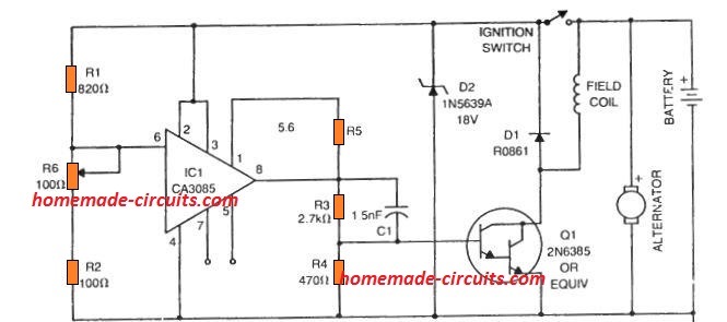
Normally while the battery voltage is below, the full charge level, the regulator IC CA 3085 output remains switch OFF, which allows the Darlington transistor to be in the conducting mode, which keeps the field coil energized, and the alternator operational.
Since the IC CA3085 is rigged as a basic comparator here, when the battery charges to its full charge level, may ba 14.2 V, the potential at pin#6 of the IC changes to 0V, switching OFF the supply to th field coil.
Due to this the current from the alternator decays, inhibiting any further charging of the battery. The battery is thus stopped from overcharging.
Now, as the battery voltage drops below the CA3085 pin6 threshold, the output becomes high once again, causing the transistor to conduct, and power the field coil.
The alternator begins supplying to the battery, so that it begins charging again.
Parts List

3) Transistorized Car Alternator Regulator Circuit
Referring lo the nest solid-state alternator voltage current regulator diagram below, V4 is configured like a series-pass transistor which regulates the current to the field of the alternator. This transistor along with the two 20 amp diodes are clamped on an external heatsink. It is intriguing to see that dissipation of V1 is not really very high even during the maximum field current, rather merely within 3 amps.
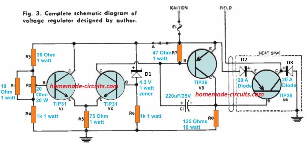
However, instead of the mid-range at which the voltage drop across the field is corresponding to that of transistor V1 causing a highest dissipation of not more than 10 watts.
Diode D1 provides protection to the pass transistor V4 from the inductive spikes generated within the field coil any time the ignition switch is switched off. Diode D2 which transfers the entire field current supplies extra working voltage for driver transistor V2 and guarantees that the pass transistor V4 could be cut-off at large background temperatures.
Transistor V3 works like a driver for V4 and a base-current swing of 3 ma to 5 ma upon this transistor allows total "on" to full "off" switching of V4.
Resistor R8 offers a route for the current during excessive temperatures. Capacitor C1 is essential to protect against oscillation of the regulator because of the high gain loop that is created around the the system. A Tantalum capacitor is recommended here for increased precision.
The primary element of the control-sensing circuit is enclosed within the balanced differential amplifier consisting of transistors V1 and V2. Special concern had been provided to the layout of this alternator regulator is to make sure there is no temperature drifting issues. To achieve this most linked resistors must be wire-wounds types.
The voltage control potentiometer R2 deserves specific consideration as it should never move away from its settings due to vibrations or temperature extreme conditions. The 20-ohm pot employed in this design worked ideally well for this program however nearly every good Wirewound pot in the rotary style might be just fine. The rectilinear trimpot varieties must be avoided in this car alternator voltage current regulator design.
The zener reference diode is important. Not just because it sets voltage reference but also because it controls system temperature coefficient. So the differential amplifier is made temperature-stable to stop drifting. It uses known diode coefficient about -0.04% per degree centigrade.
Now how it works is simple. When engine speed goes up then battery voltage also goes up. This makes charging current increase.
If field current stays same at start then higher battery voltage increases base current of transistor V₂. Then base current of V₁ also increases but less than V₂. This happens because of resistor network R₁ R₂ R₃ and R.
Ok… since collector current of V₁ goes down and V₂ collector current goes up, something interesting happens. Current in resistor R stays about same because it comes from V₂ collector current and V₁ base current. So when V₂ collector current increases, it must make V₁ base current smaller. This also reduces alternator field current.
Because of this alternator output voltage comes back to almost same as before. How close depends on regulator gain. In this case gain is very high.
Now about the setup. Transistors V₁ and V₂ are put on heat sinks. Not because they need cooling but to keep them strong.
Best if they stay close together so no temperature difference happens between them. The reference zener CR has its own place.
4) IC 741 Car Alternator Voltage Current Regulator Charger Circuit
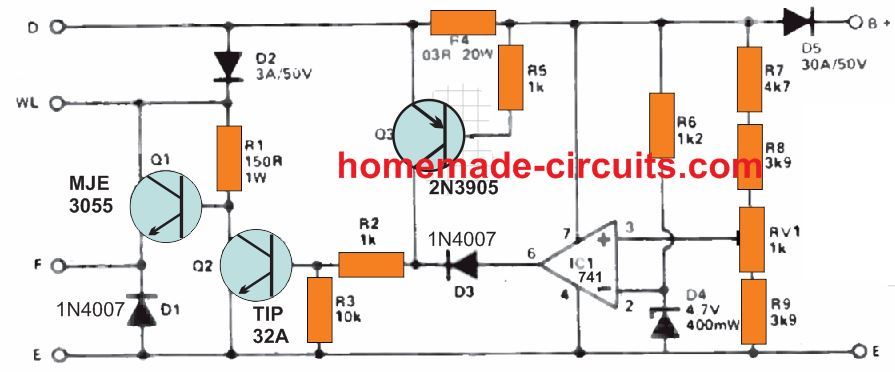
This circuit offers solid-state management of battery charging. The alternator's field winding is in the beginning stimulated through the ignition light bulb just as in a traditional method.
Current moving across the WL terminal travels via Q1 to the F terminal then finally on the field coil. As soon as the engine is powered, current from car's dynamo moves through D2 to Q1. The ignition tell-tale lamp fades out since the WL terminal voltage exceeds than that of the battery. Current likewise moves through D5 towards the battery.
At this point, IC1 which is rigged as a comparator detects the battery voltage. When this voltage on the non-inverting input becomes higher than the inverting input (clamped at 4.6 volts via zener D4) causes the output of the op amp to go high.
Current subsequently passes via D3 and R2 towards the Q2 base and instantly switches it ON. This action as a result grounds the Q1 base switching it off and removing the current applied on the field winding. The alternator output now drops, causing battery voltage to also drop correspondingly.
This procedure ensures that the battery voltage is always held constant, and is never allowed to be over charged. The battery full charge voltage can be tweaked through RV1 to roughly 13.5 volts.
During cold weather conditions while starting the car, the battery voltage may drops significantly low. As soon as the engine has ignited the battery's internal resistance also become quite low, forcing it to pull too much current from the alternator and thus leading to a possible deterioration of the alternator. In order to restrict this high current consumption, resistor R4 is introduced within the primary power terminal from the alternator.
The R4 resistance is selected making sure that at highest possible current (Commonly 20 amps) 0.6 volts is generated across it which causes Q3 to turn ON. The moment Q3 activates current moves through the power line through R2 towards the Q2 base, switching it on, which then, shuts off Q1 and cutting off current flow to the field winding. Due to this the dynamo or the alternator output now drops.
No modifications need to be made to the original wiring of the alternator in the car. The circuit could be encased within an old regulator box, Q1, Q2 and D5 must be attached to an appropriately dimensioned heat sink.


Questions & Answers
I need a circuit to disconnect the field winding of an alternator when the battery voltage goes over 14.4V. (when the battery is fully charged the regulator cannot maintain a low enough voltage)
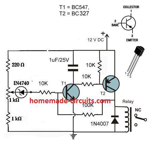
I think the attached circuit would work – the relay NC contacts connect to the field winding – but ideally I would like the relay to drop out when the battery drops below 13V
Yes it should work as mentioned, however since the relay will latched, the battery will not be restored again when it reaches the discharged level.
Love your website! Hope this isn’t off topic here, but I am searching for an easy supercapacitor balance board. Even just the resistor version would do. I want to experiment with 6, 2.7 volt 500 Farad caps, as a replacement for my racing motorcycle battery. I could charge it up in the morning and ride it all day. Lighter than even a new lithium battery pack.
Hi, thank you, and glad you liked my website.
I don’t think a balance charger would be required for supercapacitors in series, since they are not like batteries and tend to be highly stable and accurate with their charging specs.
The only think that may be crucial is the 2.7 x 6 = 16.2 V limit, which must be dead fixed while charging the capacitor block.
To be on the safer side, use a 16V constant supply for charging the series capacitors.
Only voltage has to be fixed and constant, current is immaterial for charging capacitors, it can be of any value.
I hope it makes sense!
Hello Swagatam. I would like to know why in the first circuit I have to detect the current.
I see that T4 affects the reference voltage. I do not understand why it is necessary?
What is the reason why T4 and R9 are needed?
I am very interested in your answer. A cordial greeting
Hello Yoan, the main purpose of the circuit is to safeguard the alternator from rising voltage and current. If the current control is removed, the alternator winding may be subjected to a rising high voltage and current due to the rising speed of the vehicle, causing burning of the alternator winding.
2) A Simpler Car Alternator Voltage Current Regulator
hi my name is
Mark im probobly dislexic and cant spell and what you people call easy and basic i struggle to understand…….. as i am a visual learner and struggle with text as i find it easyer to see some one do something hearing and seeing rather than the eyes closed method TEXT ONLY were you hear some thing in your head only…….. any way i need to convert this simple basic alternator regulator to 48 volts nominal for a solar alternator project ……….. i have the project alternator up and running at 57-68 volts DC but i need to regulate this to about 57.6 and it would be nice to add a pot and resistors to adjust the regulated voltage from 55-60V ………. any help or replys will be answered…….. i would be greatfull even if you know were i could copy one from …i am not lazzy and would like to understand the workings out of how to get there from here … to a bread board or find one on another site to make as some curcits say i need a cap of uf2200 but do not say it should be 50volts or 5 volts oil filled ..papper . electrolitic then it will say i need a 330 ohm resistor and i dont know if a 1/4 amp or a 5amps resistor is needed……. were as you my say thats basic information……… it would be nice to see it on a curcit diagram were it says uf2200 50volt oil filled cap ……… if you have no positive input for me keep it to your self and attack some one eles haters goner hate perfectionests going to point out my short commings and spelling mistakes ….. i know i cant spell but it hasnt stoped me yet looking for some to help that has made many mistakes and will continue to learn by making more mistakes in the future thanks in advance a no reply will be better than some one pointing out all the mistakes in this email so if you can give me a hand pushing my voltage regulator cart up hill i will be great full i live in a rural area in Queensland Australia ..Atherton 4883
ps i am greatfull for the many skils i have spelling and electronics is not one of them
Mark
Hi, you can try the following shunt regulator to control your alternator output to the desired levels:
You will have to fine tune the 10k preset until the 48V elevl regulation is achieved. You can replace the 1N4007 diode with a RED LED for an appropriate indication
The op amp can be IC 741
thanks for your reply im not smart enough to read the circuit …..building on a bread board … i have the opamp and reverse biased zeners the 10k resisters are they 1/4 amp or larger?? ……so this can be directly connected to my 48 nominal battery ? ……. and i dont see were the field coil would be connected to regulate the alternator??…..as i saw it in my head as 48V power comeing from battery not the alternator ..into shunt regulator being regulated and out put from shunt regulator to field coil for regulation ………..fine tune the 10k preset does that mean the more ohms/ R ………if yes would i start @11k or 10500 ……….. do you have a paypal account?? ……. leg #3 of the opamp goes to the middle of a 10K.R is this a 10k pot? please understand i am just a beginer …….and the 12v ZEN looks like it connects to ground just want to check its not some netural point ground that connects the circuit as i saw some ground symbols were it didnt mean real ground
You are welcome, this circuit is not a field-coil based regulator. This circuit is supposed to be connected across the bridge rectifier DC from the alternator, so that the MOSFET of the circuit shunts the DC to ground whenever the output tends to cross the maximum limit.
Fine tune means, adjust or rotate the preset knob until the shunting is fixed at the intended voltage level.
Yes pin3 of the op amp goes to the center leg of a 10k preset or a trimmer.
The ground indicates the negative line from the bridge rectifier DC.
I have a PayPal account, but no problem, paying may not be required.
ok thanks for that Swagatam so do i run the field at full voltage from the battery then ?
You are right Mark, you can use full battery DC for the field coil, according to me…
thanks Swagatam will have a go at building this circuit … i am looking at another circuit with a PTC 80C thermal resister that i would like you to help me understand a lot better… but i would need to pay you at least something if you help me …… as i dont have any thing elese to offer you unless you need help with something ……. what would you like help with ???? Mark from Australia FNQ
No problem Mark, I am glad to help without any charges, if I ever need any help I’ll surely reach out to you.
If you are having problems reading the PTC codes, here’s one article which has all the relevant information
https://www.mouser.in/datasheet/2/281/S0410E-1140926.pdf
ok thanks for your help im just concerened at 48-56 volts the amount of amps going into the field of the alternator
I think the field winding rating and the stator winding rating should be the same. If the alternator stator winding output is 48V, then this should be the limit for the filed winding also. Current is immaterial if the voltage rating is not exceeded….Here since we are limiting the stator output to 48V through the shunt, the field winding will be also limited to this value and will be safe.
You can inquire about this with an auto mechanic, or check the specification manual of the alternator.
Alternatively you can employ the following concept which is field coil controlled regulator circuit.
The transistors are well rated to handle upto 80V
Thanks Swagatam just waiting on some BJTs will make the first one and try it out …. the second design looks good to and has the parts list GREAT….. i need to practice so will build them both will send pics when done contact me if there is something i can do for you…….. send me your paypal address and ill buy you lunch ..Mark
No problem Mark, I can understand that you want to compensate for my dedicated efforts, and I appreciate that, but truly, paying is not required because when I am answering to comments I am actually enjoying it, and having lots of fun….so no issues at all.
Let me know once you have built it then I will help you to test it and finalize it hopefully.
thanks for your reply i live in a remote area in Australia just wondering were you live …NOT your address just a round about zone in the world or perhaps not just interestered
Hi, from India, my exact location is provided in the contact page.
THANKS will buy you lunch latter on ……. i have some PNP BJTs so i have order some NPNs will see if i can make them smoke…………. best wishes and regards for your assistance i was stumped and just needed a little help………. expecting to build 3 or 4 before getting any were near understanding the 48v alternator regulator …… smoked the first alternator 12volts 50amps put to much voltage in to it……… got 60volts 15amps out at 24volts into the field….. then got gready and not understanding feed about 8 amps at 60v back into it …….finished with smoke …….have installed the spare im not dismayed have learnt a lot will purchase more old alternators as im not finished yet …….. my 48 volt victron 240v inverter arrived today hoping to pair it up with my 48v alternator and a NS60G yanmar single cylinder diesel engine and batterys as a pure sinwave generator ….rather than purchase a generator…… as the victron inverter can run off solar during the day and the alternator when needed well hope you read this in your spare time Mark ..best wishes stay safe ……sorry im off topic gone
Thank you Mark, this time your alternator will not smoke for sure, since the recommended circuit is a tested one. I wish you all the best for the same, let me know if you run into any problems….
motorcycle voltage regulator picture from you …WAS READING THE PICTURE TO ORDER CORRECT PARTS (1)…R4 10K pot dosent seam to connect any were … +.. or ground ?? (2) SWITCHED BATTERY + ( IGN SW ) TO RECT ….@ …RECT …IM UNSURE IF MY ALTERNATOR HAS THE EXTRA DIOEDS IS THERE ANY OTHER WAY TO JUMP IT … OR TEST IT TO SEE IF IT HAS THEM WITH OUT DISASEMBLY AS IT APPEARES TO CONNECT TO 3 OF THE 3PHASE LEGS ON THE AC SIDE IF I NEED TO JUMP IT WHAT SIZE DIOEDS AND VOLTAGE SHOULD I USE PLEASE … JUST HOW I TYPE ….PS NOT YELLING no hurry waiting on parts thanks Swagatam
If the diodes are not present you can add them externally, any 10 amp diode can be used for the bridge rectifier and the associated diodes.
the pot upper end is unconnected.
thanks about R4 10K pot thought it was a printer eror stay covid safe
Hi can I use this to control the field circuit of a 48 volt alternator
The above circuits might require a lot of modifications to work with a 48V alternator, so I guess it may not be a feasible idea.
I am looking for an alternative to the old style mechanical viltage regulator and your first circuit
above, would do nicely.
I would need to build it using stripboard (veroboard)
Do you have a drawing of the layout for assembly, using that system please, or could you post one to the site?
regards Nick (Australia)
The solid state regulator would replace the one mechanical one (70 years old) on my Ferguson Tractor.
All the circuits shown in the above article can be used as direct alternative for the mechanical type. You just have to interchange the relevant matching pins of the electronic design with the mechanical one.
Hello,
I am looking to build a regulator/cut-out to suit a 6V motorcycle dynamo (Bosch RD45/6). However unlike the dynamos used on most British machines where the field and armature are bonded together at the earth (frame) with a control resister switched in or out ( between D+ an F) the Bosch type are quite the opposite. I.e it’s the out-put (D+) and field that are bonded with the control resistor being inserted at the earth end (D-) Looking at the above circuits it would seem to me that I would either need to modify the internal wiring of the dynamo or look for different circuit. Also the external wiring of the bike incorporates an ignition/charge light, this connected to the battery via the ignition switch and the out-put (D+) directly – not via the cut-out. I should be grateful for your thoughts. Thank you.
Hello, if you don’t want to open the alternator, you can apply a shunt regulator externally and still regulate the alternator AC, explained in the following article:
https://www.homemade-circuits.com/motorcycle-full-wave-shunt-regulator
Thank you for your reply. How ever I think I may not have been fully clear in my question.
A Bosch RD45/6 dynamo is a DC generator, not an alternator ( AC generator). Would the circuit still work by simply omitting the bridge rectifier? However without it would the circuit still act as a cut-out ie. prevent the battery discharging through the dynamo windings when the machine is at rest?
PS can images be added to comments?
You are welcome! Yes the bridge rectifier can be avoided and replaced with a single diode on the dynamo side, and another diode at the output side to prevent battery discharging through the associated resistors.
Sorry, image uploading facility is not available here.
Hi,
How would I go about / change for correct components to build a regulator to control a 24v Dynamo, spent the last 6 months trying to acquire a mechanical regulator with no success.
Many tx
Nick
Hi, no changes will be required, except the preset adjustments, rest can be as is.
Hi. My name’s Mathew and I loved your site. Been searching for a schematic like this for some time. The first schematic was tested in real life? I’m prone to build it in order to make a static generator with a small motor and an alternator I have lying around. So, I need to charge a static battery (deep-cycle), and to do that – having in mind that I need to preserve the battery lifespan – the charger will require a voltage cap (around 14,5 V) and a current cap (around 10% of battery discharge current, 6 A). By the description the circuits just fits perfectly. The warning lamp have any critical parameters?
Thank you in advance, keep up posting great schematics and analysis like that!
Thank you Mathew, yes all the circuits above were tested by experienced engineers!
The warning lamp is critical, since it also delivers the required amount of current to the field col, you can use any 12V, 3 amp lamp for this.
P1 adjusts the over charge cut-off voltage for the battery, while R2 adjusts the current limit.
if the battery is fully charged then regulator will reduce the field current to ZERO? If the field current is zero and bettery voltage falls below then how will alternator start without initial excitation from battery ( start switch and lamp) ; mean to say that it can not start from zero field voltage and current. I mean it may be never coming to fylly ZERO? Really what happens?
According to the diagrams, the power to the field coil will switch OFF completely, until the battery starts consuming the charge current again. However, the alternator will remain operational through the vehicle engine, and as soon as the battery discharges, the supply to the field coil will be instantly restored back….
HI Swagat ; I am thinking to make vertical axis wind turbine using car alternator. I could not find suitable PM low rpm alternator at suitable price. For alternator, here the case is different as compared to vehicle. The turbine will start/stop 1000 times in a day and secondly always RPM not sufficient. So if I give field excitation continuously then battery may get discharged. So I am thinking to detect rotor RPM by Hall sensor module and if it is sufficient then I will supply field current from battery for say 1 sec and then remove for self excitation. In this way I will avoid unnecessary drainage from battery by field coil. How do you like this idea? Pl comment.
Hi JK, the idea sounds perfectly OK to me.
Hi Swagatam
Hopefully I’m in the right place now….
I’m hoping to build a (voltage) Adjustable Alternator Regulator for the engine in my sailboat.
The pic I sent had the PotMeter fitted to the circuit board. I was hoping to have the PotMeter remotely located around the chart table area where the Volt/Ammeters are located.
I’ve got three reasons for wanting to building my own regulator…
Reasons being:
-Fixable. Too much gear nowadays is so complicated it’s near impossible to repair.
-Adjustable. Not many regulator controllers do what I need as a liveaboard
-Cost. The ones that do everything I want are absolutely stupid money (£650+)
I was thinking of having a relay on the field output wires linked up to a voltmeter which has relay outputs in the event of the voltage going through the roof (for whatever reason), the relay would cut the power, hopefully reducing damage to other electronics onboard.
Unfortunately I’m a total electronics novice at the moment but will be learning what I need to complete it (Fingers crossed)
How do you think I/we should go about changing this dream into a reality ?
Brilliant website, by the way. I’m hoping it’ll teach me what I need….
Hi Neil, I checked your diagram, it seems quite OK to me:
However, I am not sure how accurately the PTC would respond?
Hi Swagatam
The PTC would be bonded to the alternator to reduce the output in the event it get too hot, so I suppose it doesn’t have to be too accurate, compared to what It would have to be if it was controllng the battery temperature/voltage.
Do you think, by locating the potmeter 10 ft away it would cause any problems ?
OK, then it’s fine!
I don’t think the 10 feet distance of the pot location would cause any problems since the op amp inputs are high impedance and therefore slightly higher resistance of the wires will not make any difference.
Do you have a diagram that would do a better job, maybe with a little modification ?
Your diagram looks quite good, any other modifications could make the design more complex.
I found what i was looking for a simple Alternator voltage regulator. I may have new way to push pistons in an engine thus getting rid of the EMC. Which controls the voltage regulator in my alternator right now. I will replace the whole assembly for what you have presented. Thx so much, God bless
Glad you found the post useful. All the best to you!