In this post I have explained a simple constant current bicycle dynamo battery charger circuit which can be used for charging a Li-Ion or Ni-Cd battery from a bicycle dynamo electricity source. The idea was requested by Mr. Saif Khan.
Technical Specifications
I want to charge a battery through a dynamo fitted to a cycle. Can you please tell me how to design the circuit for it. I don't know electronics. I will be really grateful.I don't know much but i live with electronic engg guys who know about it so if given a complete schematics they can do it. Can i order these online?
I am not sure a dynamo would be able to produce 28/30V. I have read that it can be limited to 4-20 V mostly
(I am using a simple motor..which will rotate and as well charge the battery). I know i am a total noob.
Just few points:
1. The input voltage, being connected to a dynamo fitted to a normal cycle will vary a lot but mostly be less than 20V, right?
2. The Li-Ion battery that will be charged needs to power an LED lamp for about 2 hrs. It has to be charged within 1-1.5 hr of cycling. That's pretty much my project.
1) The Design
The second circuit shown in the following link can be implemented for the above application:
https://www.homemade-circuits.com/how-to-build-simplest-variable-power.html
The dynamo input should be connected across the points referred 30V and ground, VIA a 1N4007 DIODE.
The 10K variable resistor which may be a pot or a preset should be adjusted to get the desired output voltage.
The LM317 should be mounted on a suitable heatsink.
The IC LM317 can work right from 3V to 35V inputs, so input variations won't affect the outcome.
The pictorial presentation of the proposed bicycle dynamo battery charger circuit is provided below.
It must be ensured that the pinouts of the IC are correctly connected as per the shown designations.
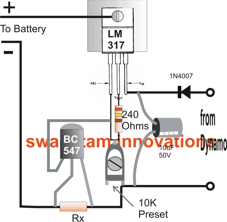
How to calculate current limit for this bicycle dynamo battery charger circuit
Rx is the current control resistor which must be selected as per the charging current specifications by using the following formula:
Rx = 0.6/charging current.
The next idea below explains how to simply charge Ni-Cd cells quickly using a dynamo device.
2) Charging 1.2 V Ni-Cd Cells (for Science Projects)
The second concept explains how to use a 6V dynamo for charging 3 Ni-Cd cells or Ni-Mh cells in series.
The design was requested by Mrs. Jennet through email, as given below:
"My daughter is in grade 10 and her science project is to charge a small battery using an exercise bike and a dynamo. Would you be able to assist in a schematic for this, as well as advise on what needs to be purchased in order for this to be built? Any assistance would be greatly appreciated. "
Materials Required
The materials required for this bicycle dynamo converter project are:
- 6V Dynamo = 1no
- 1.2V AAA Ni-Cd or Ni-Mh Cells = 3nos
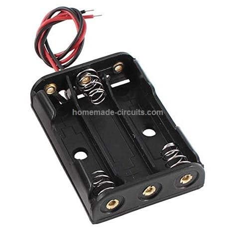
- 4.5V Battery Box to Fix the above cells in series = 1no
- 10 Ohm, 2 watt resistor wire wound = 1no
- 1N4007 Diodes for making Bridge Rectifier = 4nos
- Any Cheap Small 100 mA Ammeter = 1no (optional, for indicating charging status)
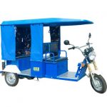
The image of the battery box can be seen below:
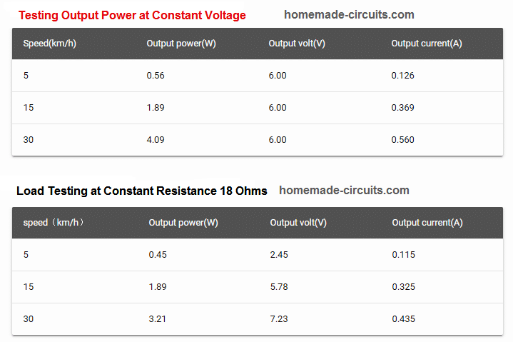
Dynamo Specifications
The dynamo specifications can be studied from the following data:
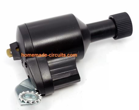
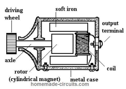
It is basically a 6V dynamo, with a maximum current capacity of 500mA. Even at a slow bicycle speed of 5 km/hour, this type of dynamo will produce a decent output of 6V @ 100mA. This power could be used for charging an Ni-Cd or N-Mh cells or even a Li-Ion cell. Li-Ion cell might take a long time to charge at this rate, unless a buck converter is employed.
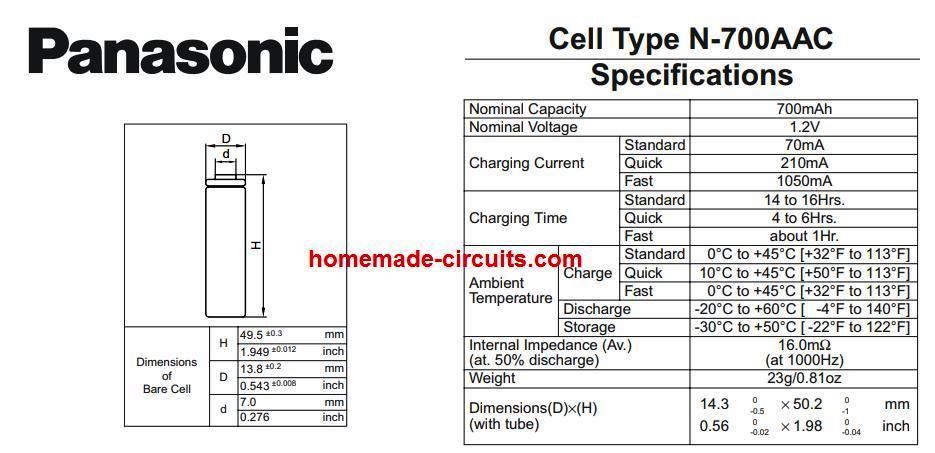
The cell specifications could be as indicated below:
How to Connect Dynamo with Battery
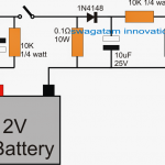
Connecting the dynamo with the battery and the rest of the mentioned parts can be implemented using the following wiring layout:
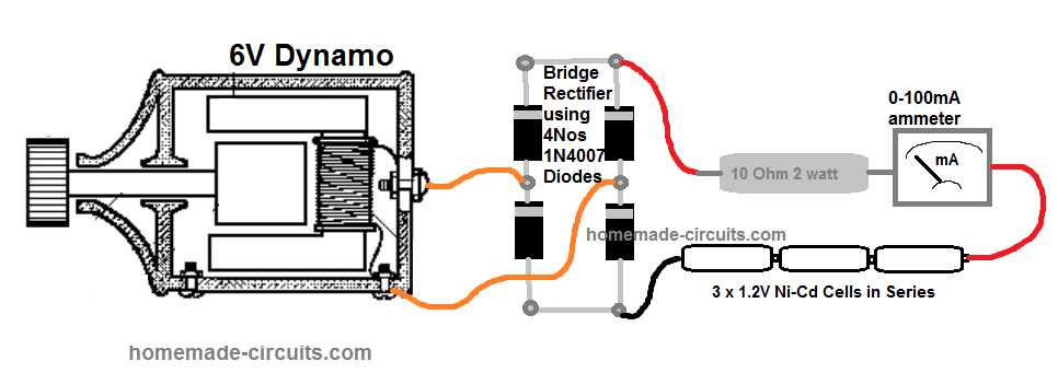
The connections look pretty simple. You will need a soldering iron and solder wire for joining the shown parameters.
Begin by making the bridge rectifier using 1N4007 diodes, as explained in this article.
Next, insert and fix the cells in the battery box.
After this, install the dynamo on the bicycle frame.
Finally, join the ends of the shown components using flexible wires with one another. Be sure to connect the ammeter with correct +/- polarity, otherwise the meter needle will deflect towards the left side instead of right side. (+) of the meter will go to the 10 ohm resistor.
Warning: Since the dynamo body acts like one of the output terminals, make sure it does not come in contact with any of the wire connections of the circuit, except the point where the lower orange wire is hooked up. In short, keep the diode side circuit secured inside a plastic box.
Testing the Charging Response
Once you have finished the procedures, start peddling the bicycle. You will start seeing some deflections on the ammeter. This will indicate that the battery is consuming power from the dynamo and is getting charged.
Now, as the bicycle is operated continuously, the battery will gradually get charged. This will be indicated by proportionately reduced deflection on the ammeter.
Until, finally no deflection or reading on the meter will be seen, which will indicate that the battery is now fully charged.
Bicycle Dynamo Battery Charger Circuit with Relay Changeover
By employing rechargeable batteries in the backup unit, the necessity for battery replacement is eradicated. The batteries remain on charge whenever the dynamo is in operation.
To minimize losses, no electronic devices are inserted into the source/lamps circuit.
In dynamo systems, the bicycle frame is typically utilized as the return current path by securely connecting one terminal of the dynamo to the frame.
Some commercial backup units demand isolating the dynamo from the frame, which is a challenging task.
The system described here, however, doesn't impose such a constraint, making it more accessible for both current and future dynamo users.
The output characteristics of all dynamos closely match the lamp load. In most setups, a 3W dynamo provides power to a 6V, 0.4A, 2.4W front bulb and a 6V, 0.1A, 0.6W rear bulb.
Regrettably, when the front bulb burns out, the rear bulb also fails shortly thereafter. When the rear bulb fails, the increased brightness of the front bulb significantly shortens its lifespan.
In fact, the authors once measured the open circuit voltage of a wheel-driven dynamo and recorded a peak-to-peak reading of 180V on the scope while pedaling in 10th gear!
Selecting the Right Battery
Regarding the battery choice, typical AA-sized NiCds boast a capacity of 500mAh and recommended charging currents of 50mA and 150mA for 15 and 4 hours, respectively.
When the bicycle is stationary, the total current supplied to both lamps by a battery composed of four NiCd cells is approximately 0.45A.
Consequently, a fully charged battery will last for approximately 45 minutes without dynamo assistance. It's important to note that under normal circumstances, the battery will not be utilized in this manner.
In situations where space is limited, the smaller 1/2A-sized NiCds offer the same capacity as the AA size but occupy only about half the space.
Additionally, non-rechargeable cells can be employed if necessary. In such cases, the charging circuit components D2, D3, R2, and C2 can be omitted.
If over-voltage protection is unnecessary, the zener diodes can also be excluded.
How the Circuit Works
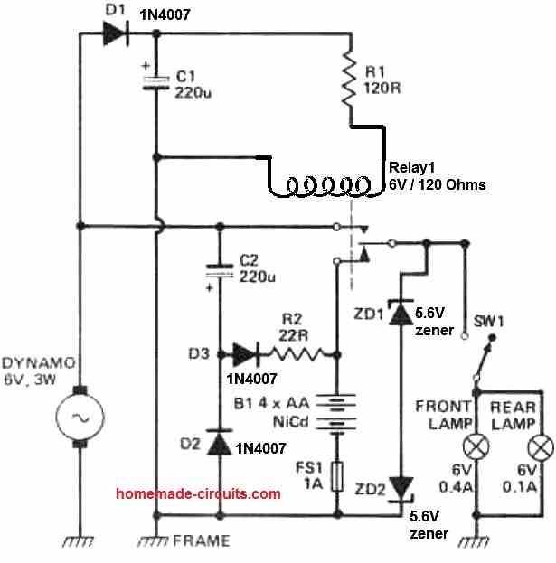
The diagram presented above illustrates the entire circuit configuration for this unit. D1, C1, and R1 collectively supply DC power to the relay coil.
The point at which the bicycle's speed triggers the transition from battery to dynamo power supply for the lamps is determined by the component labeled B1.
For the particular Union model dynamo used, a speed of 20 feet per second yielded a smooth transition with minimal light flickering.
D2, D3, C2, and R2 constitute the charging unit.
Voltage regulation is accomplished through the back-to-back zener diodes ZD1 and ZD2. There are two operational modes:
a) Normal mode, with SW1 turned on: When the dynamo is stationary, the lamps draw power from the battery.
As the dynamo's voltage increases, the relay engages, and the lamps switch to dynamo power. The peak charging current in this mode is approximately 50mA.
b) Fast charge mode, with SW1 turned off: If the dynamo is engaged with SW1 turned off, the charging current increases to around 90mA.
This mode is useful for expediting battery charging while riding in daylight conditions. ZD1 and ZD2 play a critical role in limiting the voltage.
Without them, the charging current would surge to excessive levels, potentially causing damage to the NiCd cells.

Questions & Answers
I enjoy your articles. Have you any article to test those small rectangular battery used in mosquito rackets ? Can you rejuvenate this battery by topping with distilled water ? Any practical circuit to charge/monitor this battery ? Previously they used two nicad 1.2Volt cells.
Thank you for your kind words!
A mosquito racket battery can be perhaps revived using a desulfator circuit, as explained in the following article:
https://www.homemade-circuits.com/battery-desulfator-circuit-explained/
Distilled water cannot be added because these batteries are sealed type.
Two 1.2 cells might not work because the mosquito bats works using 4V supply.
To monitor low voltage you can integrate the following circuit with the battery:
https://www.homemade-circuits.com/low-battery-indicator-circuit-using-two/
The resistor values might require some changes for monitoring a 4V battery.
Hi if i make the Rx=0 ohms will the current be the same as the dynamo output current?
Hi, yes that’s correct. If you don’t want current limiting, you can simply remove the transistor and replace the Rx with a short.
Thanks
Hello! I’m writing to request bicycle circuit to draw as much power as possible and as efficiently as possible from bicycle axial dynamo
Idea is to boost voltage with switching circuit, similar to Joule thief and then step it down using commercially available step down boards
Made me also wonder if could treat existing dynamo windings as inductor of sorts, switching it to higher voltages and working out from there, maybe also using MOSFET rectifiers for least power drop possible, or Schottky diodes
I’d personally aim for 22V DC out at least to charge all possible devices
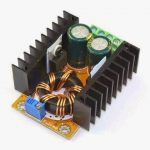
Hello, it won’t be a good idea to boost and then step down the dynamo voltage, that would cause wastage of energy. Instead you can directly step down the dynamo voltage using any standard buck converter unit.
Congratulations on having this knowledge…. I would like to have the opportunity to have a dynamo or something similar that charges an electric visor at the same time as using it, the battery would charge and test your knowledge, I would greatly appreciate it if you could provide me with my name, Jose, thank you
Thanks Jose, can you please give the specifications of the battery, and the electric visor or the load….i will try to figure it out…
Dynamo already have very low voltage 8,5V at its peak when cyclist goes fast, not to mention voltage drop on diodes and fact most step down boards require 4,75V at least
Stepping up would make rectification less punishing and most of sine wave could be used to produce useful power, resulting overall with more power for devices
Ideally would be designing AC in step up/step down circuit rectifying with either MOSFET perfect diode or Schottky , but that would be much more complicated in my opinion
And 22V was kinda arbitrary minimal voltage to be able to charge silly things like laptop or power 12V car devices
OK thanks. You can boost it to 22V for high voltage applications, and then reduce it to other level for other low voltage applications.
Thanks for the interest! Just wonder what would be more efficient, switching inductor to boost voltage or hand wound 1:4 ferrite, and if so, how many turns would be optimal
I’ve never got around figuring these things out, same for AC boosting Joule thief
According to very minuscule amount of data, frequency of dynamo is around 50Hz at peak power
You can perhaps try the following circuit:
The coil can be built using 50 turns on an iron bolt
Hey it’s me again, I think I found what might be an ideal solution, remaining question is, what version would be cost efficient
Active non-isolated PFC converter, good video explaining them on youtube Jv2JVorAeiE
I lack skills to calculate proper values for much lower power requirements as these designs are usually meant for 1kw or more, but simpler, less efficient design using cheap IC or even 555 oscillator could work (for this purpose might limit voltage to 18v max to power it), also hub dynamo itself could be used as inductor, but I lack meter to precisely narrow down hub windings inductance
Hey, if you are looking for a boost converter circuit then the circuit which I suggested in my previous comment should work nicely. The power can be easily modified by modifying the MOSFET rating.
hallo sir,
could i change the dynamo, with litle fan 12 volt dc?
Hi Rudi, yes you can, but the it might not charge the battery unless its current output is adequately rated
Sir,
Have no questions yet but appreciate topics regarding battery chargers. Will be reading your articles. Thanks
You are welcome Melvin…
Sir i am a mechanical engineer pl sujest me i need a dynoma for mobile charging system dynoma rotate per hour 10 kilometers there are 5 leds bulbs and mobile charging round the the clock dynoma rotating mobile charging should exceed normal level pl advice me with crcuit diagram suitable dyonoma and where is available address pl urgently pl give miss call to 9480106295 / 9449950392 sincerly
Hello Nagabhushan, you can try the last circuit for charging the mobile phone, the meter will not be required and the 10 ohm resistor should be replaced with a 2 ohm 2 watt resistor. For the LEDs you can use 20mA 5mm LEDs, put all of them in parallel, make sure to have a 100 ohm 1/4 watt resistor in series with each LED
Hi I’m 16 and am creating a dynamo – battery charging unit for a DT project. I don’t have any expertise in electricals and was wondering if you could help me understand how to use / adapt this or another circuit to suit my need and also where to purchase all the necessary components.
Thanks.
Hi, I can surely help you. Please let me know the battery ratings that you are going to use. Or you can simply tell me about the dynamo specifications, so I can suggest which battery could be suitably used with it, and other related parameters.
yes it can be used
helo sir,
i want to know what about Rx. what is the use of it.
helo shiva, it's for restricting the charging current to the desired safe limit as fixed by the calculated value of the Rx
Hello, I have build a robot with battery switching feature. Another part which I am currently working on is to generate energy from the robot's motors using dynamo. The dynamo would charge the system's battery one at a time based on the voltage conditions. My question is, what is the appropriate considerations need to be count in while designing the battery charging part. I mean how should I modify the above circuit to a lithium polymer friendly circuit. I am using a 3 cell 11.1V 2200mAh lithium polymer battery. Looking forward for a reply.
Hi, the above circuit does not have an automatic over charge cut-off feature which may be highly recommended for a lipo battery.
I'll design the required circuit soon and post it in this blog for your reference.
Sir i want to make a hand cranked mobile charger for 2000mAh battery. How design circuit and dynamo.
Suyog, there are many circuit options possible, you can use a 7805 IC, or a LM317 as shown above or any other similar voltage regulator with a bicycle dynamo for getting a cranked charging output for charging the cell phone.
The above circuit example is the best that you can get.
Hello, swagatam
The above circuit is very nice. I seen a hand cranked flashlight circuit, there is no electronics in it, not even a diode, the dynamo is wired through a series of LED and a double contact switch. the LED working both as a variable rectifier and light source. its the simplest design… can you explain/post the circuit?
Hello Max,
Thanks!
The Hand cranked device that you are referring to might be having output limited to LED voltage that's why no other parts are involved, a bicycle dynamo voltage could range from zero to 20V making it essential for some sort of regulation to avoid LED damage.
I'll try to investigate the details.
you are welcome!
I am sorry Karaveer, i have discontinued the offer because it could get too confusing to handle and publish so many responses.
But no issues, if you have any elaborate topic to learn or discuss with me, you can send it to homemadecircuits@gmail.com, I'll respond and publish it as effectively.