Making a simple DIY inverter circuit is very easy if you have a few transistors (BJTs), MOSFETs or one oscillator IC. The main work of all these circuits is same. They take direct current from battery and change it into alternating current using transformer and some switches.
Different types of circuits are there to make inverter. Some use two transistors to make own pulses, others use MOSFETs or separate ICs to control transformer.
In this article we will check five simple inverter circuits. These use different parts and methods, so you can pick one what you need.
Let us see how these different inverter ideas compare.
Simple Inverter Circuit Using Cross-Coupled Transistors
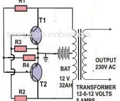
This is most basic way to make inverter with two power transistors. Both transistors are connected cross-coupled, meaning they switch ON and OFF one by one without any extra oscillator IC.
This design is good for learning how transistor inverter works. It uses very less parts and center-tapped transformer.
If you want to see how this simple transistor switching works, check complete circuit and details here:
Simple Cross-Coupled MOSFET Inverter Circuit
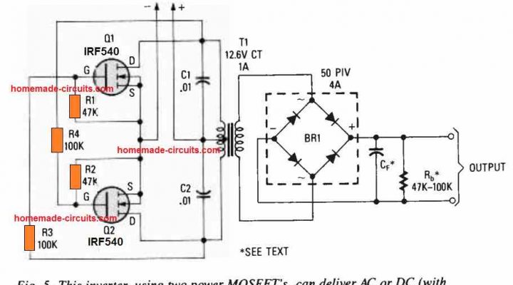
In this circuit, we use MOSFETs instead of normal power transistors for switching. Cross-coupled connection is same, but switching parts are changed to MOSFETs.
MOSFETs are very common in power section because they can handle high current easily if circuit design is correct. This circuit helps to understand how same cross-coupled idea works with MOSFETs.
Read complete circuit here:
Simple Inverter Circuit Using IC 4047
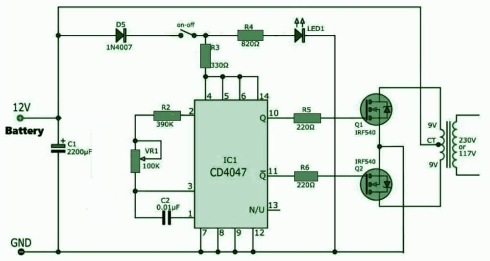
IC 4047 is very useful chip for making inverter oscillator. It gives two square wave outputs from opposite sides to control push-pull inverter stage.
Best thing is we do not need to build extra transistor oscillator to make switching signals. IC 4047 does timing job, and external transistors or MOSFETs handle transformer load.
This is good design if you want inverter using special oscillator IC.
Read complete circuit here:
Simple Inverter Circuits Using CMOS ICs 4049, 4011, 4093 and 4060
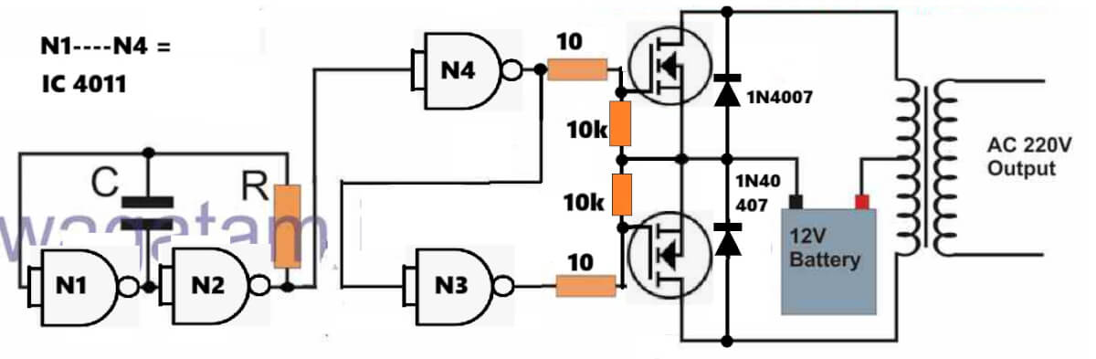
We can also make inverter oscillators using different CMOS logic ICs. This article shows ideas using IC 4049, IC 4011, IC 4093 and IC 4060. These ICs can be set up to make timing signals, which can drive external transistor or MOSFET power stage.
Interesting thing is we can try different CMOS ICs to get switching pulses. Every IC has different internal setup and working style. So if you have these CMOS ICs in hand, you can check these designs in detail article.
Read complete circuits here:
Simplest 100 Watt Inverter Using BJT Astable as the Oscillator
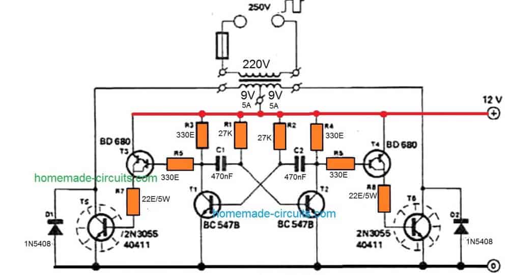
This design uses separate BJT astable multivibrator circuit to make switching pulses. These signals are used to run power transistor stage connected to transformer.
Main idea is making oscillator part using normal transistors instead of one oscillator IC. This design is made as simple 100 watt inverter test. But real output power depends on transformer, battery, transistors and how you build it.
You can check full schematic and part details in this article.
Read complete circuit here:
Which Type of Simple Inverter Circuit Should You Choose?
If you are confused which one to select, check this table:
| Inverter Design | Main Switching Method | Main Feature |
| Cross-coupled transistor | Two power transistors | No separate oscillator IC |
| Cross-coupled MOSFET | MOSFET switching stage | MOSFET-based power switching |
| IC 4047 inverter | CMOS oscillator IC | Complementary timing outputs |
| CMOS IC inverter | Logic IC oscillator | Different oscillator options |
| 100 watt BJT inverter | BJT astable multivibrator | Separate transistor oscillator |
What Should You Check Before Selecting an Inverter?
Before building any inverter, first decide how much output power and battery voltage you need.
For example, small inverter for running small lamp needs different transformer and power stage than inverter for heavy load.
Transformer is also very important. Primary winding must match battery voltage and inverter switching setup. Secondary winding must give correct AC output voltage and current.
We must also check switching frequency, transistor or MOSFET rating, heatsink requirement and battery current.
One more important point is output wave. Most simple circuits here are basic square wave inverters. Do not think they are pure sine wave unless proper filter or SPWM part is added.
Lastly, never select circuit just by seeing big wattage claims. Battery, transformer, switches and wires must handle full load safely.
How to Choose the Right Transformer VA Rating
Many people make mistakes while selecting the transformer for these simple inverters. If you use a small transformer for a heavy load, then it will get very hot and burn out.
For 50 Watt to 100 Watt Output: Use a 9V 0 9V or 12V 0 12V transformer with at least 3 Ampere to 5 Ampere current rating.
For Higher Loads: If you want more power, then you must use heavier wire in the transformer primary winding and bigger MOSFET or transistors on a proper aluminum heatsink.
Matching Primary and Secondary: Always check that primary side matches your battery voltage (like 12V) and the secondary side gives the correct AC voltage according to your country standard, like 220V or 110V.
Common Troubleshooting Tips
If you build the circuit and it is not working, then check these common things first: Check Battery Voltage: Sometimes battery is low or discharged so the oscillator will not start switching.
Check Transistor or MOSFET Pin: Wrong pin connection can instantly destroy transistors or ICs. Double check base, collector, emitter for BJTs, or gate, source, drain for MOSFETs.
Check Oscillator Working: If you are using IC 4047 or CMOS ICs, then check if the timing capacitor and resistor are connected properly to create pulses then. You can check the output pins using a multimeter or small LED.
Transformer Wiring: Make sure the center tap is connected to the positive battery line (or negative depending on the circuit design) and the outer end go to switching devices. Wrong transformer wiring will not produce any AC output.
Important Safety Rule While Testing Inverters
High Voltage Danger: transformer secondary output gives 220V or 110V AC. This voltage can give a severe electric shock or fatal injury. Never touch live transformer output wires with bare hand while the circuit is switched ON.
Use Fuse Protection: Always connect a proper fuse between the battery and the inverter input circuit. If there is a short circuit, then the fuse will blow and save your battery and transistor from burning.
Heatsink is Compulsory: Power transistors like 2N3055 or MOSFETs like IRF540 will get very hot during operation. Always bolt them to a good aluminum heatsink using mica washer and insulating paste.
Conclusion
We can make simple inverter circuits in many ways using normal transistors, MOSFETs and CMOS ICs.
Some designs use cross-coupled transistors for direct switching, while others use IC 4047 or other CMOS ICs for oscillator signals.
These five inverter designs give different options to try basic inverter building.
You can check individual articles for circuit diagrams, parts lists and working details. Select design based on your battery voltage, power need and parts you have.
Always check full circuit and parts rating before connecting battery and transformer. AC output can give heavy shock, so use proper insulation and safety during testing.

Questions & Answers
hello sir how can I intergrate Ics sg3524 and using ir2110 as a MOSFET driver thanks
yes that’s possible
please help me with its circuit I want to setup one thanks
I am just too interested in inverter making but I don’t have any knowledge in electronics or electricals. Please how can you help me.
Hello I want to know which of all the inverters published on this site is better for devices such as smart tv, led tv, pc, and notebook .. Thank you very much. From Buenos Aires Argentina.
yes it can be used for all SMPS based appliances.
Hello, sir, thanks for the reply, but which one of all …
All of them can be used.
Thank you very much for your quick reply. My question is for the type of wave … I just wanted to know if they are safe for last generation devices … Thank you very much from Buenos Aires Argentina.
Any sinewave or modified sinewave inverter will be be good. But any 250V square wave inverter will also work because all the mentioned appliances are SMPS based and therefore will ultimately convert the AC into DC regardless of the waveform.
Thank you very much for your quick reply. That’s what I wanted to know. Thank you very much, you are a genius. Greetings from Buenos Aires, Argentina
You are most welcome Carlos!
Sir.
Those are good and interesting projects and i must say that i appreciate it and all of your circuits have been working well with me and also improving on my studies…
but i must say i am sorry for asking this favor here….
Sir do you have any project for car theft?? i dont mean car alarm, if i set the gadget on, the car works on a timer, if someone takes off with the car, at certain distance the car automatically stop moving such like engine gets stoped or battery cutts off, if also a schematic that can work like GSM will also be appreciated…
thanks for understanding and i will be looking forward to be reading from you again.
Nkwenti.
Hi Nkwenti, GSM may not be required for this simple application, it can be done with a small timer circuit integrated with the ignition system. However how do you expect the theft to happen, is it by manipulating the ignition wires or by stealing the ignition keys or through duplicating the keys..because the circuit design will depend on how it is triggered.
Sir all i wanted was a simple schematic that can be adjusted to indicate car speed step by step and then from that step by step i can do additions to it to stop or quench the car engine… where i am i do not fine audinor’s so a schematic that is not that complicated is what i am seeking for.
thanks for your reply sir.
nkwenti, please type tachometer in the search box on top right you will be able to find the required design.
Sir can i replace the 2n3055 with TIP142?
TIP142 is a Darlington transistor so I am not sure how it might react, but there’s no harm in trying. I would recommend TIP35 instead
ok sir… i will try TIP35 and also the darlington and give you my feedback… thanks for your help and guide… youre truly a teacher.
you are welcome nkwenti!
you also sir…. well the reason why i ask if i can use TIP35 was because i came accros this circuit from a website which had your labels so is this a good working circuit? then i was wondering why 3kva will run only with 12vdc instead of at least 24vdc.
here is the link.
2.bp.blogspot.com/-OV6ZWLz_JW0/UmjW3hdGB6I/AAAAAAAAFjk/AQTrzhS3gGE/s1600/3kva+inverter+circuit.png
This circuit was copied by many other websites. You can find this circuit and even better ones under this category:
https://www.homemade-circuits.com/category/dc-to-ac-power-converters/
it is a good circuit but won’t produce perfect sine wave, to get perfect sinewave you will SPWM instead of normal PWM.
output wattage depends on the battery specs, transformer specs and mosfet specs…..which can be easily modified and upgraded as per user preference.
Mr swagatam. Good day.. let me ask you again. I have inverter refrigerator but the board is dead. Can I direct it by using a simple circuit design? The main supply is 230 single phase AC mains and the output is 330 dc 3 phase. Thanks mr Swagatam.
Hello mark, do you want to discard the existing board and replace it with a new circuit? In that case you can specify the remaining things from the inverter which you want to include in the system, and specify their specifications, I may try to help!
Hi Swag,
aim looking for a 12v to 19.5 3.5A DC Dc inverter. do you have it any such in inverter circuit?
Regards.
Hi Paaker, you can try the following concept
https://www.homemade-circuits.com/12v-car-laptop-charger-circuit-using/
Thanks Swag. this is what aim looking for.
by the way this circuit aim going to power up a LCD TV not for charger. it can be use as power supply TV right?
Regards.
Hi Paker, yes it can be used for the said purpose, but the coil and the switching frequency will need to optimized correctly for getting the intended results.
The coil wire dimensions could be modified for achieving higher current outputs.
Sir good morning!! can i use 1 amp trafo and smaller transistor like tip 31? ill use it with 3 to 7 watt bulb.
Hi Jindro, yes you can do that…
Helo sir, pls I need more light on inverter transformer winding…
Am just confused…
I want to know how to wind inverters transformer of different capacities.
But my concern now is how to choose or know the :
=> swg for any inverter transformer capacity.
=>size of lamination core ,
=>related calculation for each capacity before winding…
=> how to know or determine the required voltage at the primary like 230,220 volt etc
I want to do inverter of different capacities and I don’t want to make mistakes with the transformer winding…
Hello Akinbi,
you can refer to the following article:
https://www.homemade-circuits.com/how-to-design-your-own-inverter/
although the max capacity will be 10 amps only.
Hie sir I’m new in electronics . Can you help me on the difference between square wave and sine wave
Hi Binus, if you switch ON and OFF a 12V supply the output will be in the form of a square wave because the output suddenly rises to 12V and then suddenly drops 0V, but if you do the same in such a way that the output slowly rises from 0V to 12V and then slowly drops from 12V to 0V then it will be in the form of a sine wave.
Helo sir, help me on how a capacitor is said to be a dc blocker and ac bypass whilst it is found in some dc powered circuits
Binus, all capacitors have this property. They block DC because DC forces a capacitor to charge in one direction only, and with no return path to discharge the capacitor blocks any further entry of the DC. Whereas an AC being alternating current provides the capacitor a discharge path on each cycle or pulse, thus enabling its continued passage for the subsequent cycles.
Thanks sir I understand now
Is it somehow possible to achieve with easy means, to get out of my 4 solar panels (4×34=136VDC)
the same Voltage but AC, to power my fridge (100W)?
I only find circuits with transformation from lower Voltage.
Snote
You will need an inverter circuit for this, probably a sinewave inverter since a refrigerator is involved. You may need one of these:
https://www.homemade-circuits.com/2017/10/5kva-transformerless-inverter-circuit.html
I am sorry there’s no easy way of implementing it.
Thanks for your reply. Apprechiate a lot.
But this looks like too much for me. I will stay with the
SMPS and the phone and computer. For the fridge I have to search for another solution…
Snote
Sure, no problems!
Can I use a 12v 30A car fuse for my solar panels?
I have 8 panels a 250W with 34V each.
I would connect 2 strings of 4 panels in series.
So I got 136V and 2000W = 14A.
Is this right?
When you connect the panels in series the watt will remain the same as for a single panel. So the total current will be 7 amp (@136V). The fuse should be also rated at this same value
Hi Sir Swag, can i use a rechargeable 12v9ah silicon gel type battery on the above last circuit, my load is a 20w LED bulb and/or a small fan (during power outage in my place)?
Hi Amor, yes no problem, you can use it.
Hi Sir Swag, i’ve built the last circuit above successfully but in less down an hour my new fully charged 12v 7Ah battery drops to 10v so fast and the 2n3055 getting too hot to touch, my heatsink is 4inch L and 1.5inch W is this too small?
Hi Amor, what is the load that your using, how much is its rating in watts?
my load was just a 2w LED bulb
then I think your circuit has some problems, cut the base of 2N3055 and check if it still gets hot or not?
Sir, after disconnecting both base of two 2n3055 then both remain cool nothing happen, battery stays at 13v
do you thinks there is a wrong connection or grounded even i made to lit a bulb?
Hi Amor, I think there could be problem with your transformer. Check the current by keeping ammeter in series with the battery positive, with load and without load.
Hi Sir Swag, the current in series with battery positive is 2.57amp stable without load and 2.33amp with a 1.5w led bulb and its dropping every minute. my trafo is a 9-0-9/0-210-220 6amp.
Hi Amor, that looks too high. It means even without a load your inverter is wasting 2 x 12 = 24 watts? There’s certainly something wrong. Make sure your IC is generating the required frequency and the mosfets are actually good.
Hi Sir Swag, do you think my trafo is causing why its consuming too much current even without load? because i’m using a step-down trafo instead of a step-up? i already replace the entire circuit and the result is the same. should i use a step-up trafo?
Hi amor, step up, and step down transformers are one and the same. When you use it with a AC mains it becomes step down and when you use it with an inverter the same trafo becomes step up.
you can perform one more check. Remove the mosfet gate connections from the IC, and connect them to the ground line. Now check the current consumption, If it’s zero then the culprit is the transformer, not the mosfets.
In that case you may have to replace the transformer with a new one.
Thank you Sir, i just thought step up and step down trafo is somehow different in windings of primary and secondary coil. anyways Sir what i’m building is your last circuit above using 2n3055 and TIP127 not the one using IC and mosfet Thanks.
Thanks Amor, in that case disconnect the base of the 2N3055 and connect them to ground for the mentioned verification
Hello sir.. How are u.. Sir one question about your second cricuit diagram where cd4047 ic used.. Problem coming from my cricuit is that when i connect the 7-0-7 5amp transformer to the two terminal of cricuit then my mosfet (irfz44n) is heated and i connect load to like 100w bulb then the mosfet will excess heat and bulb is not glow… What behind reason for this i cant understand.. So please help me sir..
Apurva, if your mosfet is heating up without load then either your IC is faulty or mosfets are faulty, or there could be some other connection fault.
first make sure the mosfets do not heat up without load. And If on load it is heating up then you must attach a heatsiink with the mosfets
Hello sir one problem is also occur. the ic will be damaged now when we give the load on transformer then mosfet will heat after that the ic will be damaged.. I check it now.. I purchased new ic it is also damaged… All connection will be correct i used 104 16v ceramic capictor, 100ohm 1/2watt resistance. All components connected properly sir..why it occurred i cant understand..
Did you connect D1, D2 across the mosfets?
Yes sir i used in4007diode on both side mosfet..
Then there could be some other fault in your circuit, or may be the mosfets are itself faulty. Is your transformer making slow buzzing sound when switched ON?
Yes Sir…. But when i connect 100w bulb then the sound will be stop and mosfet will now heating start..
solder the transformer wire directly to the bulb ends. Do this first then touch the battery positive with the inverter positive and see what happens.
You can also do this with a 40 watt bulb first and check the results
Sir i made this transformer by own hand i used 18swg wire in secondary side means (7-0-7) side and 25 swg in primary side.. Can i used correct wire gauge for this transformer winding..??
Sorry, in that case I can’t help. Please buy a good quality readymade transformer for getting the expected results!
Hi sir, can you help.
(a) With the aid of diagram explain how a magnetic hysteresis loop can be developed.
(b) Draw the hysterisis loop and label on it.
(c) Explain on these terms.
(i) magnetic saturation or saturation flux density.
(ii) reminant flux density.
(iii) coercive force.
Hi Binus, this explanation is already available online from other websites, with diagrams. You can easily check them out.
Sir can you provide a simple inverter circuit using hf transformer that can be found in mobile chargers…
Deepu, it is difficult to make inverter from a mobile charger transformer, even we if succeed in making the output power will be very less.
Sir, i have a 1080p mini wifi camera which operates on battery, can this wifi camera be operated on ac, if this is possible can you help me..
Hi Rikseng, does it have a DC input socket, for an USB port? Otherwise it can be a little complex to implement an AC based operation.
Yes it has dc input socket and one usb cable is included with it.
Then you can use apply 5V to the socked through a readymade mains AC to 5 DC adapter, and operate wi-fi with an AC input
Hi sir swag,please i how can i recharge the battery used for the inverter without removing it?
Hi Abdur, you can try the following concept:
https://www.homemade-circuits.com/single-transformer-inverterchargerchang/
Hello Swag,i would like tu use an external clock on the CD4060 to produce a 200KHZ output the only problem is that my 4060 is unstable with a quartz of 4mhz or 12 mhz (i have repected the pf capacitor value!
thank you
Hello Mathieu, please refer to the last diagram from this article, and connect the crystal in the shown manner:
https://www.homemade-circuits.com/how-to-understand-ic-4060-pin-outs/
hi, would you do a 10 kw three phase full sinus inverter ? I’d appreciate it if you could share the circuit diagram.
plz tell me the cost of project. if possible individual cost of the components also attach with the components name.
Each of the projects will cost around 700/-INR to 800/-INR without cabinet and battery. The transformer is the costliest part and will cost around 500/-INR (9-0-9 / 5amp). The battery may also cost around 1000/- INR
Hi sir, please can you help me with post me your powerful inverter 2000w integrated battery charger circuit diagram. Thank you
Hi Saeed, you can try applying the last concept in the above article….
Hi , your program site is very useful and didactic.
Thank you!
Hello! I am trying to make my own 240v inverter to power solar panels for residential use. what size charge controller and inverter I do I need and I also need a wiring diagram to make the inverter itself. please if you could help. Thank you!!!
Hi, You can get all the details in the following post
https://www.homemade-circuits.com/how-to-calculate-and-match-solar-panel/
Thanks very much
Fully informative
100% sharing with no gaps
What about running your home with two darling transistors at 600v 80amp near 12000kw to 17000kw at 120/240v with an input from some solar high voltage source 600v combined with a a few 9 amp solar cells.
I’m building an inverter using a 555 time ic but the problem is that when I try to step up the voltage I can’t get any voltage at the secondary coil…what could be wrong. .?
Bonjour Monsieur,
I read with great interest your “7 very simple inverters”. I need such a simple inverter for modelism with the following requirement : going from 12 Vdc to 12Vac no more than 1A. I got a 6-0-6/12 transformer. What will be your recommendation in term of choice between your 7 solutions ?
Best regards
Claude
Thank you Claude, you can get 12V ac across the 0-12V winding of the transformer. So you can build any one of these inverters and get the 12v ac from the primary side of the transformer
sir, i have try to modify existing 12-0-12/ 220v transformer from old amplifier board. the steel bars are very rusty, i m tring to rewind secondary with this voltage 12-6-0-6-12 /220 for inverter. but i forget turn while re-winding .i get this voltage at secondary output 12-6-0-5.5-12 /220 . i want to use that 6-0-6/220v for inverter.
my question is that will inverter work in this 6.0-5.5 windings.
Shankar, yes it work but the output AC waveform will proportionately uneven across the positive/negative half cycles.
sir , how i can send you my circuits for conformation of working and errors.
this is a circuit from old dvd power supply https://drive.google.com/file/d/1-CJJvCDKoe8oHlkO9eRVo7vO_9ZPcRI0/view?usp=sharing
i want to make it 5v 2amp usb charger circuit from this ic.(switching buck regulator)
it uses la5752 ic and input 12v supply and output +12v ,-12v ,and 5v .
Hi Shankar, please check the datasheet of the IC, you will find a suitable circuit diagram in it which you can probably use for constructing the 5 V charger
Many thanks, sir for your blessing !
Claude
Hi Swagatam,
The transformer used in “UNIVERSAL PUSH PULL MOSFET MODULE WHICH WILL INTERFACE WITH ANY DESIRED OSCILLATOR CIRCUIT” is it a 12V/220V transformer?
Regards
Jan
Hi Jan, if a square wave output is required then battery and transformer can be of similar voltage rating, but if the input is PWM then the transformer voltage will need to be proportionately lower than the battery voltage
Hi Swagatam,
I will be using PWM from the Arduino. My situation is that I have a few 12/220v 5VA transformers in stock which I would like to use for this project. Could I perhaps overcome this problem by using a DC to DC 12V – 30V converter to step up the voltage to the transformer. Will this work?
Your advice will be much appreciated.
Regards
Jan
Hi Jan, that may be possible but might result in a significant power loss. Also, 30 V looks too high, it should not be more than 20 V with regards to the Arduino code that I have used in my sine wave inverter concept
Hi Swagatam,
How much power loss can I expect?
Regards
Jan
Hi Jan, the converter may dissipate 10% power and the inverter may dissipate 20%, so in all it can be around 30% loss
Hi Swagatam,
Thank you for your reply. That is quite a lot. However, I still think it worth a try. All I want to do is to run my TV & Computer during loadshedding which lasts for 3 Hrs max. per 24Hrs.
Kind Regards
Jan
Thank you Jan, Wish you all the best with the project!
Hi Swagatam,
Please assist me with the following.
Please refer to your All P-Channel IRF9540 diagram. I have connected the mosfet’s as per your diagram but both the IRF9540 and the IRF540 gets extremely hot. I have replaced them with new ones but still getting hot. I also check the mosfet’s as per your instructions on how to check with a multimeter and yes I have blown some of them already, but replaced them.
According to your diagram the IRF9540 source-3 goes to +12V. The IRF9540 drain-2 goes to the drain on the IRF540 and the gate-1 goes to both the 9540 & 540. The source-3 of the 540 goes to -12V.
On both mosfet’s PIN 1=G, 2=D, 3=S
Is this correct because I have checked this configuration now numerous times.
Then please tell me which code I should use for the Arduino Pure Sine Wave Inverter. Your code or Mr. Anton.
I have now almost completed this project and all the modules works very nicely. This was a very interesting project for me.
Your assistance will be much appreciated.
Regards
Jan
Hi Jan, yes the indicated pinout assignment is correct for both the MOSFETs. The MOSFET woking is actually very straightforward. At any instant only one particular diagonal set of MOSFET must conduct, due to the presence of alternate logic at the input of the bridge… since there is alternate logic at the input side all 4 MOSFETs can never conduct.
You can confirm the above by adding a bulb across the “transformer” points, and then manually apply logic high and logic low across the inputs of the bridge alternately. You should find the MOSFETs working perfectly and the bulb should illuminate during both the alternate pulsing. After this you can use an oscillator circuit such as a transistor oscillator, or IC 4047 oscillator with very low frequency and check th eresponse, agaiin you shoul fid the bulb illuminate continuously without any heating.
After this slowing increase the freqeucy and confirm the proper working of the MOSFETs. I have checked the configuration using IC 555 and IC 4017, and it had worked perfectly for me.
Also make sure to add protection diodes across the drain/source of each MOSFEts. Once the results are 100% confirmed then you can go for the Arduino integration.
Thank you Swagatam,
I used Mr. Anton’s code on the Arduino. Could that not maybe be the cause of the problem?
Hi Jan, if the test procedure suggested by me in the earlier comments does not create any issues on the MOSFETs then it could be the Arduino code problem.
Hi Swagatam,
I have noticed that the mosfets do have an internal protection diode between the S & D terminals. Is it then still necessary to have another protection diode externally.
Regards
Jan
Hi Jan, yes for guaranteed safety against strong reverse EMFs separate external diodes across the drain source leads is recommended.
Hello sir
Am tried to design the second circuit which is using CD4047 IC, am test the oscillator first it work and am conducted another test using 30w, 4ohms speaker and it’s ok also.
But the problem is that when am connected the MOSFET and transformer. The MOSFET got hot some times it’s burnt. I want to use this oscillator to design dc to dc converter of power inverter using 500wtt ferite core transformer, am used IRF540 MOSFET. And also am tried to calculate the frequency of the circuit but am found 16.7khz
E.g
Ur R= 68kohms = 68000ohms
C= 01.uF =( 0.1*10^-6)F
Using f= 1/(8.8*RC)
f= 1/(8.8*68000*0.1*10^-6)
f=16.7khz. is this correct?
If yes sir may I use 22.7kohms and 0.1uf to find 50khz?
Pls sir I need ur correction base on my calculation and problem.
Hello Jamilu, I have tested the 4047 based inverter and it worked nicely for me, you can see it in the video. You can build a ferrite core based inverter using the IC 4047 and IRF540 mosfets provided the ferrite transformer winding is calculated correctly.
The result of the calculation seems to be incorrect. The -6 should be -7 according to me, and the result will be in Ohms not in kHz.
I think we should not depend on the calculations instead check the frequency directly across the IC output pins using a frequency meter that would provide us the precise reading for the frequency.
Thank you sir.
Am understood, I will try to check my work and correct it.
No problem Jamilu!
Hi! Mr swag, I will like to ask a favour of you. I have a circuit I am trying to repair it has a top232gn( HV offline switcher) ic at the power supply stage but its simple transformerless power supply stage. I will like you to help check up the ic and explain to me how it operates. I really dont understand it. Thanks a lot
Hi Joseph, please refer to the datasheet of the IC, you will be able to get a detailed explanation regarding the each pinout of the iC and its circuit functioning.
Hi Mr Swag;
I am mechanical. I removed an transformer from ups and there are 2 inputs (12 volts – black and + red) and also 3 outputs (220 volts black-yellow-blue). However all circuits I saw all their inputs like 12-0-12. In that case how I can proceed. Regards
Hi Suat, you can try applying the following bridge circuit:
connect the transformer primary across the points shown as 220V.
For the oscillator you can use the following circuit
ignore the transistor stage and the transformer, and the use the 1K ends from the 4017 outputs to connect with the above bridge oscillator inputs
Hi Mr. Swagatam, thanks for your kind reply. However I need your confirmation to check that whether my understanding is correct? as far as I understand it is possible to gain both 220 V AC and 310 V DC on the output by mixing 2 circuits you offered. Meanwhile I found another simplest circuit by means 555 and ifrz44 my output is allright about 228 AC but not able to light 40W bulb. How dou you think the problem is about hz (sin wave) or weak amper source? (my source transformer power shows 10 V not under load and it may be around 1 A) meanwhile I will use that on my car battery 12 V 60 A-Kind Regards
Hi Suat, No, please ignore the 310 V in the first diagram. It is to be used if no transformer is used with the bridge. When 310 V Dc is used as the input supply, then the output will be 220 V AC without any transformer..
For a transformer based design its wattage must be higher than the load wattage. so for a 40 watt load the transformer must be rated at 50 watts or 60 watts. A 10 V 1 amp transformer will be able to handle only a maximum of 8 watt load
Hi Mr Swagatam;
I really appreciate your remote and valuable support. I found the original USB PCB of the transformer (2 inputs 850 VA / 480 W max 5,5 A UPS pressed circuit board).
So, its input may be not 12 Volt as I mentioned before I think its original battery should be 6 Volt 7Ah. I am not sure and confused (when I imposed 12 volt AC the output was above 320 Volt AC) So if I would made a circuit regulating step down 12 Volt to 6 Volt.
(By either step up 7805 or step down 7808 and current capacity is important) Then I think I can connect my UPS to my car battery (Car Battery 12 V 60 A). So please advise whether that runs and is effective. Meanwhile I will use the equipment like 400 watt drill or grinder-cutter. In case I would add the dimmer before equipments and by decreasing their rotate speed that may gain less ampere. Please advise whether that can defect my car battery while car runs. One more time many thanks-Best Regards
Hi Suat, I have already suggested you a very good IC 555/IC 4017 circuit which can be adapted for any transformer and battery combination. The circuit will support a 6 v transformer with a 12 V battery supply and produce the required 240 output
Hi Mr Swagatam;
Please advise maximum how many times we can trigger a mosfet and / or a relay in a second. For instance in case we trigger a relay 50 times in one second does relay reply each time properly. Thanks.
Hi Suat, for MOSFET there’s virtually no limit, for a relay it may be 0.5 Hz at the max but it may slowly get degraded with time.
Hi master Swagatam;
to generate A.C. voltage from D.C. I made an simple curcuit consisting of 555 timer/osiloscope. There are tip127 and tip122 connected to pin 3 of 555 IC. Always I measure one side (at the side of tip127) 0 Volt (while base not triggered) and +8.80 Volts at the emitter (while base triggered) whereas I measure at the side of tip122 the voltage is either + 2 volts (while not triggered between 1 and 2 Volts) or 8.40 Volts (while triggered). I mean there is always plus voltage / tip122 is always active (may be we call a leakage current) although base not triggered. Tets is done on Proteus. Now please explain whether that is true when real circuit and how we can eliminate the situation.-Many Thanks
Hi Suat, you can eliminate it by adding diodes at pin3, as shown in the following example image
Sir the first inverter circuit digram that was shown, had only four resistors but in your video I saw more than four resistors,is this a scam.Please help me out.
The extra resistors were used for adjusting the values, since the exact 100 ohm and 15 ohm were not found.
Thank you sir your project is a success I built it and it works, I am so happy your not like the others.
Glad it worked, and congrats to you!
Please I can’t view the schematic diagram
which schematic?
I only see your write up but i don’t see any diagram please help to fiquer out the problem
images will appear slightly late, but it cannot disappear entirely, please refresh the page, or check yuor internet connection speed.
About 40 years ago, I made my first (square-wave) 600W inverter using a 4060 and a 4027. But instead of a RC oscillator, I used the 4060 with a 3.2768 MHz crystal so that I had a very precise 50 Hz at the outputs of the 4027. Now there are a lot of inverters available commercially, but almost all, including expensive sine-wave inverters, have only poor frequency stability. Some use a 555 ic wich frequency vary a lot with temperature. They cannot be used for sound recording equipment, like open-reel tape recorders, not even for a turntable. I later had to reuse my old circuit to make a 60Hz to 50Hz frequency converter, so that my old 50Hz turntable turns at the correct speed in Canada. The ideal would be to use two switchable crystals, one for for 60Hz, the other for both 50Hz and 400Hz avionic system.
Hi.
I want to make an inverter that can output 2000 watt -220v AC, which circuit do you recommend and what changes I need to make on the circuit.
What should be the output waveform, square wave or sine wave??
Do you do any paid consulting? If so please contact me offline.
I am from the old school. I went to electronic school in 1974-76. I am seeing some abbreviations I don’t recognize. For instance R1=10 R2 and R1,R2,R3=33E. Can you please explain what these mean?
Les
The letter “E” or sometimes R”” is equivalent to the symbol Ω, and when there’s no E, that again indicates the presence of the Ω
so only “10” means 10 Ω, and 33 E also means 33 Ω
Thanks. All of this when a simple “ohm” would suffice? Oh well, I’m one of those guys who hates abbreviations. Abbreviations are supposed to save time, but when the reader has to spend several minutes searching for what the abbreviation means, it is no longer a time saver.
You are right! thanks for the feedback!
Is there a circuit for a transformer that only got 0-12v. All this circuits use a 0-12-0. This is not to use for any appliances but mere as testing . I have got a few of this transformers.
Regards
Klaas
You can try the following concept:
https://www.homemade-circuits.com/easy-h-bridge-mosfet-driver-circuit-for-inverters-and-motors/
These are relevant information for young electronic engineers,thanks very much.
Glad it helped, and thanks for your feedback!
Hi Swagatam
If I have a 400VDC input to a half bridge inverter, I get 141.4V rms out. If I want to step up that voltage to 220V rms out, do I need a center-tapped transformer to step up the voltage or can I just use a non-isolated step up transformer (no center tap). Basically, when do I need a center-tapped transformer, and when do I not for a half-bridge inverter?
Hi Luke, You can compare the half bridge circuit like any other oscillator circuit, say for example like a IC 555 oscillator. So with such an oscillator you can simply add transistor stages and then configure your center tap transformer to get the full output.
After gone through 7 simple inverter circuits I got very much clear idea and knowledge.These are very simple and economical ,very useful. Really I got enlightened . you’ve explained different components like ICs, power transistors ,transistors and mosfets.
Awesome .Thanks a lot. हेलो ठंक्यौ .गॉड ब्लेस यू .कीप इट अप .
रीगार्ड्स
Thank you very much, I am glad the post helped you to understand the parameters related to inverters. God bless you too!
Please I need more detailed explanation on circuit 3,5 and 6
You can read this article to understand more:
https://www.homemade-circuits.com/how-to-design-inverter-basic-circuit/
I have 9,0,9v 300mA transformer will it work. One power transistor c4111 and 1k resistor
you will need two power transistors.
Thank you so much sir but the 300mH transformer oky. But the power transistor is in different number I hope it work.
Thank you so much for ur time
Chidera, 300mA is very small, it will produce no more than a few watts of output.
Good evening Sir
There was a time I wanted to make a 12V DC to 200V AC inverter, with a 12V 40AH battery. I used the cd4047 as an oscillator circuit and with 2 irf740 mosfets but as soon as I started the cd4047 to burnt and defective. I do not understand why. You can help me
Hello Daoud, It may be due to transformer back EMF spikes. Did you connect protection diodes across the MOSFET drain.source….although these are already present inside the mosfets, still it is better to connect additional diodes externally.
Also make sure to supply the DC to the IC 4047 through a 100 ohm resistor, and connect a 12V zener diode right across the Vcc and Vss pins of the IC. You must also connect a 100uF/25V capacitor right across these supply pins of the IC. All these together will make sure the IC remains safe from the transformer back EMF spikes.
Thank you very much for your guide
And for the 100 Ohm resistor is what it is for all 12V batteries as there are 12V batteries of large capacity such as 100AH, 200AH, 150AH.
what is the power of the 100 Ohm resistor that I should choose
Hello Daoud, yes the 100 ohm should work for all 12 V batteries, the Ah rating of the battery does not matter. The 100 ohm can be a 1/4 watt rated.
Merci beaucoup Monsieur. Tous mes respects
hi how’s things trevor’s my name of trevoramiss@mail.com, an Australian
what i am looking for ,it an invertor of 12 volt to 36 volt with 25amp on out put
i would like to make this invertor myself, if any of you have, a detail drawing with a list of parts, that you would like to email to myself, on the above email address, that would be grit, thank you
hi trevor, for 36V output, you just need to have a transformer with a primary side having 12-0-12V winding, and the secondary side having a 36V winding
I got your circuit with the two Moffett irf540 to work thank you. I noticed the transformer has a 12.6v CT so its a
6.3-0-6.3 correct ? Also I didn’t have irf540 i have a few different one but I can’t seem to get it to work for more then a 20 seconds before the mosfets start to smoke. Yes they are on a heating. Thank you
Which circuit did you build? For all the concepts explained above, the transformer must be around 9-0-9V with a 12V battery.
Its the 2 mosfets irf540 the transformer in your circuit is a 12.6 with CT. This circuit has 2 100k and 2 47k resistors
yes, in that circuit the center tap is rated at 6.3V because it is intended to produce a higher voltage than the normal home AC level. For 220V or 120V AC, a 9-0-9 trafo is recommended with a 12V battery.
Make sure that your mosfets are mounted on large heatsinks
Hello sir. In other inverters the output of the core transformer will be its voltage at the output is rectified and filtered which drives yet another assembly of the mosfet transistors mounted in push-pull I do not know why this assembly again I do not understand
Thanks
Hello Daoud, that type of circuits are used in ferrite core inverters. For iron core this is not required
Good evening sir, thank you for your response.
What is the importance of push-pull assembly consisting of mosfet
Hello Daoud, in a push pull inverter configuration, the current is pushed and pulled alternately through the transformer primary winding, which causes the current to transfer from the primary to the secondary winding through magnetic induction and we get the 220V output from 12V.
Mosfets can be used for delivering larger amounts of current than BJTs.
Do you have a schematic of a pure sine pwm for a h bridge boot strapping design.
After messing around with very large transformers hurting my hands winding them, I have decided to go with the transformerless design. The square wave is easy. I would like to incorporate pure sine wave. In this project
I have a related diagram in this blog. You can check the second diagram from the following article:
https://www.homemade-circuits.com/5kva-transformerless-inverter-circuit/
Thank you, I must say you know your stuff, after I sent the message I found what I needed from you very extensive blog/site. I figure I will let the smoke out
At least once but I will get. Thanks again
ART
good afternoon sir,my question: if i am connecting the board to the battery,for 70ah,12v battery,where shall i connect the thick and thiny wire and should i connect resistor and capacitor along or across the positive line? I need to get rid of confusion thanks.
Hello yusuf, which circuit are you referring to?
the inverter i want to build that makes use of ic 4047
All the details are provided in the diagram itself, please check it.
Please i need to know the components used for the construction of a 1.5kva 12v solar inverter, most importantly what the rating of the transformer is?
I also want to know what the circuit diagram can look like
Please it is urgent
Solar panel and the transformer will need to be rated at 1500/12 = 125 amps….
Thank you sir.
Please can you help me with a circuit diagram of the design of a 1.5kva 12v solar inverter showing the IC sg3524 and all other components. I can’t find any place to get such circuit.
Please my e-mail is Ifyakpara@gmail.com
you can send the circuit there
thank you very much
your response will be much appreciated.
Hello Ifeanyichukwu, from where will you get a solar panel and a transformer rated at 125 amps, and a 1000 Ah battery? Please procure them first then I will show you how you to build the inverter.
For a 1.5kva inverter the voltage rating must be in the range of 48 to 60 V.
a question. I made an inverter with 8 transistors irfz44n and oscillator cd4047 with transformer 12.0.12 why without load at the output it pulls 5A?
It means either your IC is shorted or your mosfets are shorted, otherwise this cannot and shouldn’t happen.
Good of you Sir Swagstam. I am enjoying your wide scope of experiences sir! God bless your intelligence.
Thank you Olufemi!
125 amps will drain your battery quickly.
Are u buying the transformer or u wanted to construct one by winding the coil yourself?
Anyway for a 1.5 kva u can use between 14 and 16 MOSFET to be arranged in each side 7 or 8 but is good to make it 24V instead of 12V for more efficiency.
Hello Swagatam
for my inverter I am using Lithium battery 12.8v/54ah. It is from solar universe India. But I charge it from solar panel with amici contrler. But when I connect to my fridge it trips by low battery. I think it is due to inbuilt BMS restrictions.
Can I remove the bms and use it?
Fridge is 200watt . It will require 15amp cont amp and some 75amp surge current.
54ah/3c will give 18amp .
If not can you suggest suitable lithium battery?
Thanks
Hello Jayant,
The recommended maximum wattage output your battery can provide is 12.8 x 54 = 691 watts, beyond this your battery can slowly get damaged.
So 200 watt is quite fine for your battery….this also means that the BMS may be the reason why your battery isn’t able to deliver the full power to the inverter….you can try removing and check the response.
Also please specify the voltage rating of your fridge,because 75 Amp x V of the fridge will provide the exact wattage of the fridge during surge.
Hello
I have mentioned that it is 200watts. But the starting current will be
five to six times than normal current.
My idea is ; can I remove bms which is restricting current?
thanks
I asked about the fridge voltage not wattage? I have already mentioned that you can remove the BMS and try!
Hi swagatam ..
Pls I want to design a circuit using a boost converter topology
Hi David, you can try the following circuits:
https://www.homemade-circuits.com/high-power-dc-to-dc-converter-circuit-12-v-to-30-v-variable/
https://www.homemade-circuits.com/how-to-make-simple-boost-converter-circuits/
https://www.homemade-circuits.com/12v-car-laptop-charger-circuit-using/
Hi pls accept my friend request on Facebook (eniola)
Accepted!
I am looking to build a very simple but high frequency version of “Simple Inverter Circuit using Cross Coupled Transistors” I am considering using the transistor TIP35CP and a ferrite core transformer to achieve somewhere around 20kHz. Is this possible? Is there a frequency limit using this type of inverter?
Actually I am not very sure what determines the frequency in the simple cross coupled inverter circuit. Is it the transformer primary turns and the resistors? If yes, then I think the number of turns and the resistors could be experimented to create a high frequency version of the inverter.
Hello I built the Cross Coupled 2n3055 inverter with a good result. I am now interested in the Cross Coupled MOSFET Inverter. Do the mosfets inherently run cooler than the BJT’s? Could I also use zeners instead of the mini capacitors to absorb voltage spikes? Really enjoying making these projects thanks!
Thank you, and Glad you could build the cross coupled design successfully. Yes you can try the mosfet version, you can use ordinary rectifier diodes for C1, C2. A 1N4007 might work for low power applications.
By rectifier diodes did you mean to say Zener? I am not quite sure what a rectifier diode would do in this case. Also I am wondering if maybe R3 and R4 could be 10k in order to speed up switching/reduce voltage drop from the pulldown resistors on the mosfet gates.
Zener might not work correctly that is why I recommended rectifier diode:
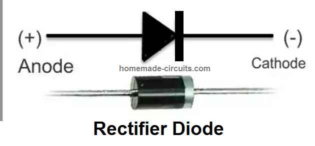
I think nothing should be changed in the diagram and the parts should be as is.
I built the cross coupled using 2n3055 power transistors. Working perfectly…handy and reliable it is.
Thank you for trying this circuit, glad it is working!
Am from Nigeria I made the astable multivibrator circuit using transistor, resistor, capacitor and mosfet but the problem is that one mosfet burn and the other mosfet just continue working but what surprised me is the despite one mosfet working and the other burnt the circuit still workes but I don’t know why
Can you please provide the link of the circuit diagram?
On the push pull inverter circuit are the gates on each set of mosfets joined together, the lines appear to be missing on the circuit. Thank you,
Yes all the gates of the mosfets on each group are joined together.
In number 3) circuit diagram below
Which number of resistor and capacitor can I use to generate clean 60hz
I think roughly it is 0.01uF and 100K, but you will have to use a frequency meter to adjust it accurately.
Hello, can I change the 2N3055 transistor to any other transistor like 2sc5200.
Thanks.
You can try 2SC5200, but it won’t be as efficient as 2N3055, because it has a high VCEO of 230V…this should be below 100 V.
Thanks
Hello Swagatam. For the Cross Coupled MOSFET Inverter, I could not find a value for the capacitor designated as Cf at the output.
Hello Simon, the Cf can be a 100 uF / 400V filter capacitor.
Thank you
good day boss.
can this project power tv and fan
Yes, the inverter designs can be used to power TVs and fans
thank you sir
Hello Swagatam, if I use any of your inverter circuits here with a 500watts round transformer. Then use 14pcs of mosfets that is 7pcs each on both sides. Then use it on a 200ah 12v battery. Can it work sufficiently or I reduce the number of mosfet?
Thanks.
Hello Morris,
Yes, it will efficiently without any issues. You can use IRF3205 MOSFETs
hello buddy, how are you doing today,am asking whether I can use an audio transistor in an inverter?
You can use any type of transistor in an inverter circuit, just make sure the current and voltage ratings match the inverter battery/transformer specifications.
In the inverter made by using cross-coupled transistors, why the two 2N3055 transistors don’t conduct together? Can you please give a more in-depth and technical explanation?
the two 2N3055 transistors don’t conduct together because the characteristics of no two transistor or inductance of the winding can be 100% identical, therefore one of the stages will start before the other, triggering the oscillating action.
Thanks for answering, I’ve one more question will it still oscillate and produce ac signal without the base emitter resistors?
It will oscillate even without the base emitter resistors.
Hello sir I wish to know you better. You’re a great inspiration to me .
I tried the one with ic 4047 using irfz3205 but after I while one stopped working and the gate resistor started heating up before this the mosfet what making noise not really audible but when I get close I could hear it and also when only one side was working I only loaded the CRT with 15watt bulb and the second mosfet went of Total what can be the cause??
although I used a 1.2amp 12.0 12 transformer
It seems like the MOSFETs are not good and have some internal defect, or maybe they are not original devices.
You can try using BJTs instead and check the response. Any power BJT such as TIP122 should work.
If BJTs work normally, then the problem is certainly with your MOSFETs.
you’re doing great! Could you please help me with the circuit of 4KVA inverter
Please provide the detailed specifications of the inverter, i will try to figure out…
l designed a simple power supply using rectifier diodes 1 n4001, 25v 470 uF Cin,7815 voltage regulator,470 uF 16 v Cout, and 220/24 vac transformer to power your simple ups battery charging circuit.
But it failed to power an already made 12 vdc/220 vac 300w ECCO inverter.
the input capacitor burned.
so what can be the problem and solution.
Please comment under the same article which you are referring to and please specify the circuit diagram also, I will try to help!
Respected Sir
I am refering to the inverter circuit (Using IC 4060). This circuit is decently made using only one output but the query is that can we use all the outputs or maximum outputs using 1 or 2.2 or 10 meg resistance??? Obviously not disturbing it’s oscillation.
Please help.
Dhananjay, All the outputs of the 4060 IC generate different frequencies, so you can select any one of them which matches the frequency of your inverter.
Hi Swagatam
Im looking at building a 200W inverter (12V -> 240VAC).
However, 9-0-9 10A transformers are difficult to get in UK.
I can however get 12-0-12
https://uk.farnell.com/multicomp-pro/mcta250-12/transformer-toroidal-2-x-12v-250va/dp/9530720
Ideally I’d like to include over temperature as well as low battery.
Would it also be possible to arrange a circuit that would allow charging of a 12V 80Ah battery using the same transformer ?
I have emailed you
Hi Paul,
With a 12V transformer, when your battery voltage drops to 11V, the AC output from the transformer could drop to 200V or lower, that is why a 9V transformer is recommended.
Yes, an automatic charger can be included using the same transformer through relays, as discussed in the following article:
https://www.homemade-circuits.com/single-transformer-inverterchargerchang/
pls sir I just the one of the diagram specifically fig 2 using cd4047 one of the transistor is very hot and one is not working although no output
what you is wrong because I use my meter and check there’s voltage flowing through the gate
Okon, I think your MOSFETTs are blown, or maybe not good.
Please remove the MOSFETs and initially try with BJTs, such as TIP122 and check the response…
With BJTs make sure the base resistor is above 1k….
hi sir…pls apart from generators,turbines or solar panels is there any other way to generate at least 12v power source reliably?
Hi Md, I think you can generate good electricity through road speed breakers…
https://www.homemade-circuits.com/generating-electricity-from-road-speed/
I wanted an inverter diagram that can produce pure sinusoidal wave at AC not square waves, can you help me with that?
Sure can try the following concepts:
https://www.homemade-circuits.com/arduino-pure-sine-wave-inverter-circuit/
https://www.homemade-circuits.com/sg3525-pure-sinewave-inverter-circuit/
Hello kind sir! Information shall be free (hopefully!)
Would you direct me please, I have 2 sets of 3 x 40volt / 6.0Ah lithium batteries (different battery systems), all new batteries, all from outmoded tool lines.
I would like to make a single inverter for the 6 batteries together, or 2 inverters, one for each set of three batteries. My design should prevent excessive current draw, and warn, then shut off as the lowest battery in the group reaches 15% SoC (state of charge,) to prevent battery damage. Ideally, the inverter could output 120 & 240 VAC, and have surge and over/undercurrent protections on the AC outputs. Ideally, I could also include DC out for USB Type A & C, also with protections as above. The AC outputs need a clean sinusoidal waveform; appropriate filters should be in place on the DC outputs.
That’s not much to ask, right? But seriously, thanks for your help, this page is already a brilliant resource! For my project, which of the designs would be a great place to start?
Hello Rod, I will surely help you with this project, can you please confirm, if your input DC to the inverter would be 40V/18 Ah for one inverter, and the same for the other inverter also? And should the inverter be a sine wave or a square wave…??