The next design is a cross coupled simple MOSFET inverter circuit will be able to supply 220V/120V AC mains voltage or DC volts (with a rectifier and filter). The circuit is an easy to build inverter that will boost 12 or 14 volts to any level depending on the transformer secondary rating.
In this circuit, the primary and secondary of transformer T1 is a 12.6 V to 220 V step down transformer, connected in the reverse format.
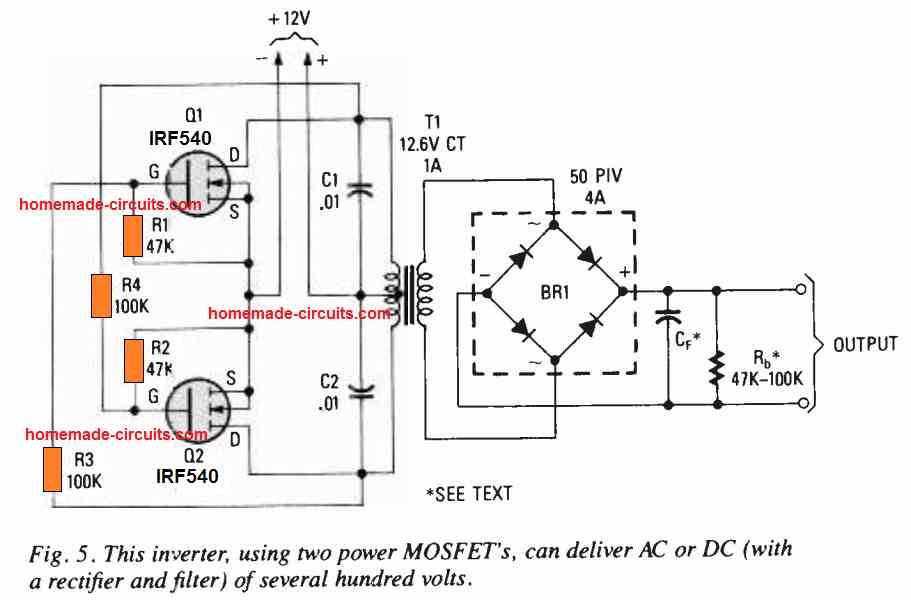
MOSFETs Q1 and Q2 can be any high power Nchannel FETs. Do not forget to apply heat sink to the MOSFETs Q1 and Q2. Capacitors C1 and C2 are positioned in order to suppress high voltage reverse spikes from the transformer. You can use any nearby value for the resistors R1-R4 having a tolerance of ± 20% to the shown values in the diagram.
The circuit is perfect to power a tube circuit, or it could be coupled with a step-up transformer to generat
Detailed Working Description
So now the diagram shows a cross coupled simple MOSFET inverter circuit designed to convert low voltage DC into high voltage AC main or DC power.
Looking at the schematic layout, it features two high power N channel MOSFETs labeled Q1 and Q2 equipped with heat sinks to manage thermal dissipation.
Now the circuit uses a transformer where the primary and secondary connections act in a reverse format, such as a stepped down 12. 6V to 220V transformer wired to boost voltage.
Capacitor C1 and C2 are placed across the circuit to suppress high voltage reverse spikes coming from the transformer winding.
So now the gates, drains and sources of the two MOSFETs are cross coupled with resistors in an astable multi vibrator or self oscillating push pull configuration, allowing them to switch alternately and induce an alternating current in the transformer.
Center tap of transformer connects to the positive DC power source like a 12V battery, while the outer terminals connect to the MOSFET drain and the sources tie to the ground.
This setup creates square wave oscillations that step up the input voltage to deliver a usable AC output on the secondary side of transformer for powering small electrical load.
Part List
To construct the cross-coupled MOSFET inverter shown in the diagram, you will need the following core electronic components:
- Power MOSFETs (Q1, Q2): 2 × N-Channel Power MOSFETs (e.g., IRFZ44N or IRF540)
- Cross-Coupling Resistors (R1 to R4): 4 × Resistors (typical values around 220 Ω to 1 kΩ, depending on operating frequency and gate bias requirements)
- Spike Suppression Capacitors (C1, C2): 2 × Capacitors (typically 0.1 µF to 0.47 µF non-polar rated for high voltage to absorb inductive spikes)
- Transformer (T1): 1 × 12V-0-12V Center-Tapped Transformer (used in reverse: 12V secondary connected as input, 220V/120V primary connected as AC output)
- Power Source: 1 × 12V DC Battery or High-Current DC Power Supply
- Thermal Management: 2 × Aluminum Heat Sinks with insulator pads and mounting hardware for the MOSFETs
To determine the timing values for the cross coupled astable oscillator stage of MOSFET inverter, you use the standard astable multivibrator frequency formula:
frequency = 1 / 1.38RC.
In this formula, f represent the target output frequency in hertz, R is the timing resistor value in ohms and C is timing capacitor value in farads.
For a 50 Hz output frequency, you can use several standard component combination.
One reliable option is using 68 kilohm resistors with 0,22 microfarad (220 nanofarad) capacitors which yields approximately 48.8 Hz.
Another option is using 33 kilohm resistors with 0.47 microfarad (470 nanofarad) capacitors, giving about 48.9 Hz.
Alternatively, you can use 100 kilohm multi turn potentiometers paired with 0. 15 microfarad capacitors to precisely fine tune the output to 50 Hz using a frequency counter or multimeter.
For a 60 Hz output frequency, common standard combinations include 56 kilohm resistors with 0.22 microfarad capacitors for approximately 58.7 Hz, or 27 kilohm resistors with 0.47 microfarad capacitors for around 56.9 Hz.
Additionally, it is recommended to place small resistors ranging from 22 ohms to 47 ohm directly in sery with the MOSFET gates to suppress parasitic ringing and high frequency switching oscillations during transitions.


Need Help? Please Leave a Comment! We value your input—Kindly keep it relevant to the above topic!