The circuit of a simple 100 watt inverter discussed in this article can be considered as the most efficient, reliable, easy to build and powerful inverter design. It will convert any 12V to 220V effectively using minimum components. However the output AC will be a square wave.
Introduction
The idea was published many years back in one of the elecktor electronics magazines, I present it here so that you all can make and use this circuit for your personal applications. I have explained more.
The proposed simple 100 watt inverter circuit disign was published quite a long time ago in one of the elektor electronics magazines and according to me this circuit is one of the best inverter designs you can get.
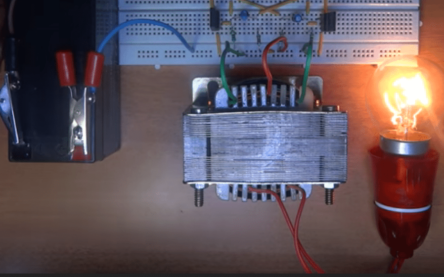
I consider it to be the best because the design is well balanced, well calculated, utilizes ordinary parts and if done everything correctly would start working instantly.
The efficiency of this design is in the vicinity of 85% that's good considering the simple format and low costs involved.
Using an Transistor Astable as the 50Hz Oscillator
Basically the whole design is built around an astable multivibrator stage, consisting of two low power general purpose transistors BC547 along with the associated parts consisting of two electrolytic capacitors and some resistors.
This stage is responsible for generating the basic 50 Hz pulses required for initiating the inverter operations.
The above signals are at low current levels and therefore requires to be lifted to some higher orders. This is done by the driver transistors BD680, which are Darlington by nature.
These transistors receive the low power 50 Hz signals from the BC547 transistor stages and lift them at higher current levels so that it can be fed to the output transistors.
The output transistors are a pair of 2N3055 which receive an amplified current drive at their bases from the above driver stage.
2N3055 Transistors as the Power Stage
The 2N3055 transistors thus are also driven at high saturation and high current levels which gets pumped into the relevant transformer windings alternately, and converted into the required 220V AC volts at the secondary of the transformer.
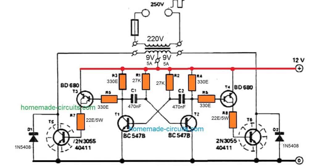
Parts List for the above explained simple 100 watt inverter circuit
- R1,R2 = 27K, 1/4 watt 5%
- R3,R4,R5,R6 = 330 OHMS, 1/4 watt 5%
- R7,R8 = 22 OHMS, 5 WATT WIRE WOUND TYPE
- C1,C2 = 470nF
- T1,T2 = BC547,
- T3,T4 = BD680, OR TIP127
- T5,T6 = 2N3055,
- D1,D2 = 1N5402
- TRANSFORMER = 9-0-9V, 5 AMP
- BATTERY = 12V,26AH,
Heatsink for the T3/T4, and T5/T6
Specifications:
- Power Output: 100 watts if single 2n3055 transistors are used on each channels.
- Frequency: 50 Hz, Square Wave,
- Input Voltage: 12V @ 5 Amps for 100 Watts,
- Output Volts: 220V or 120V(with some adjustments)
From the above discussion you might be feeling thoroughly enlightened regarding how to build these 7 simple inverter circuits, by configuring a given basic oscillator circuit with a BJT stage and a transformer, and by incorporating very ordinary parts which may be already existing with you or accessible by salvaging an old assembled PC board.
How to Calculate the Resistors and Capacitors for 50 Hz or 60 Hz Frequencies
In this transistor based inverter circuit, the oscillator design is built using a transistorized astable circuit.
Basically the resistors and capacitors associated with the bases of the transistors determine the frequency of the output. Although these are correctly calculated to produce approximately 50 Hz frequency, if you are further interested to tweak the output frequency as per own preference you can easily do so by calculating them through this Transistor Astable Multivibrator Calculator.
Another Simple Transistorized DC to AC Inverter Circuit
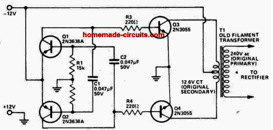
This circuit is a cheap DC to AC or DC to DC inverter that does not need any expensive toroidal transformer. It works like an oscillator driving a power amplifier.
The small transistors q1 and q2 (2n3638a) with resistors and capacitors form a multivibrator running at about 1200 hz. This high frequency lets you use smaller filter capacitors and standard old filament transformers handle it without much trouble.
If you need to lower the frequency, then you just make capacitors c1 and c2 bigger. That switching signal goes through resistors r3 and r4 to drive two heavy-duty 2n3055 power transistors (q3 and q4).
They push heavy current back and forth through the 12.6v center-tapped side of transformer t1. The transformer steps that voltage up to 240v AC on the original primary side, which you can hook up to a rectifier if you want DC.
You need to mount the 2n3055 transistors on a proper heatsink because they get hot, and pick a transformer big enough for your power needs since efficiency is around 60 percent.
Parts List
| Component Reference | Part Description / Number | Quantity | Function / Notes |
| Q1, Q2 | 2N3638A PNP Transistor | 2 | Oscillator and driver stage |
| Q3, Q4 | 2N3055 NPN Power Transistor | 2 | Main power switching output stage |
| R1, R2 | 15 k$\Omega$ Resistor | 2 | Base bias and feedback network |
| R3, R4 | 220 $\Omega$ Resistor | 2 | Transistor base current limiting |
| C1, C2 | 0.047 µF, 50V Capacitor | 2 | Astable multivibrator timing capacitors |
| T1 | Filament Transformer (12.6V CT to 240V) | 1 | Step-up transformer for AC mains output |
| Power Rails | 12V DC Supply (-12V and Ground) | 1 | DC input power source |


Need Help? Please Leave a Comment! We value your input—Kindly keep it relevant to the above topic!