This is a very easy and popular circuit to make a small power inverter. An inverter takes low voltage DC, like from a 12 volt car battery, and changes it into 220 volt AC household electricity. This specific circuit uses a special integrated circuit chip called the CD4047 to do the main job.
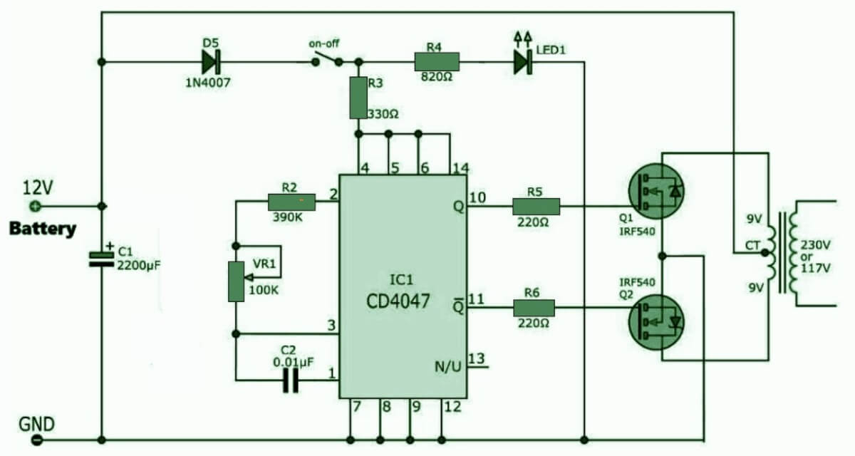
As shown above a simple yet useful little inverter can be built using just a single IC 4047. The IC 4047 is a versatile single IC oscillator, which will produce precise ON/OFF periods across its output pin#10 and pin#11.
The frequency here could be determined by accurately calculating the resistor VR1 and capacitor C1. These components determine oscillation frequency at the output of the IC which in turn sets the output 220V AC frequency of this inverter circuit. It may set at 50Hz or 60Hz as per individual preference.
The battery, mosfet and the transformer can be modified or upgraded as per the required output power specification of the inverter.
For calculating RC values, and the output frequency please refer to the datasheet of the IC
Video Test Results
HOW THE CIRCUIT WORKS IN DETAIL
The heart of this circuit is the CD4047 IC chip. This chip acts like an electronic clock or oscillator. It makes two square wave signals that switch back and forth. One signal comes out of pin 10 and the other comes out of pin 11. These two signals are opposite to each other, meaning when one is high, then other is low.
These signals go to power transistors or MOSFETs. The transistors act like heavy duty switches. They take the 12 volt battery power and push it back and forth through the primary side of a center-tapped transformer.
Because the current changes direction rapidly, it creates a magnetic field that steps the voltage up. On the other side of the transformer, the secondary winding gives out the higher 220 volts AC that you can use to light up small bulbs or run low power devices.
MAIN PARTS NEEDED
| Component Reference | Part Description / Number | Quantity | Function / Notes |
| IC1 | CD4047 Astable/Monostable Multivibrator IC | 1 | Main oscillator and pulse generator chip |
| Q1, Q2 | IRF540 N-Channel Power MOSFET | 2 | Main power switching transistors in TO-220 package |
| D5 | 1N4007 Rectifier Diode | 1 | Reverse polarity and input protection diode |
| LED1 | Standard 5mm LED | 1 | Power and operation indicator |
| R2 | 390k ohms Resistor | 1 | Oscillator timing network component |
| VR1 | 100k ohms Potentiometer | 1 | Frequency adjustment preset |
| R3 | 330 ohms Resistor | 1 | Supply voltage dropping and current limiting resistor |
| R4 | 820 ohms Resistor | 1 | LED current limiting resistor |
| R5, R6 | 220 ohms Resistor | 2 | MOSFET gate drive and suppression resistors |
| C1 | 2200 uF, 25V Electrolytic Capacitor | 1 | DC input filter capacitor |
| C2 | 0.01 uF Ceramic/Film Capacitor | 1 | Oscillator timing capacitor |
| Transformer | 9V - 0 - 9V Center-Tapped Transformer | 1 | Step-up transformer for 230V or 117V AC output |
| Switch | On-Off Toggle/Slide Switch | 1 | Power control switch |
| Battery | 12V DC Battery | 1 | DC input power source |
TIPS FOR BUILDING IT
Make sure your transformer connections are correct and do not touch the high voltage output side when the circuit is turned on because then it can give you a dangerous electric shock. Always use a heat sink on the power transistors so they do not overheat.
Troubleshooting the IC 4047 Inverter Circuit
Sometimes the inverter may not work properly even after all the components have been connected correctly. The problem can be related to the IC 4047 oscillator, MOSFETs, transformer, battery or wiring connections.
Here are some common problems and their possible solutions.
1. Inverter is not producing any AC output
If the inverter is switched ON but there is no voltage at the transformer output, check the following things:
- First, check whether the 12V battery supply is reaching the circuit.
- Check the polarity of the battery connections.
- Measure the voltage between pin 14 and pin 7 of the IC 4047. It should receive the correct supply voltage.
- Check whether pin 10 and pin 11 of the IC are producing alternating square wave signals.
- Check the MOSFET connections, especially Gate, Drain and Source.
- Make sure the transformer primary winding is connected correctly.
If the IC is not producing any output pulses, check the timing resistor and capacitor connections around the IC 4047.
2. MOSFETs are heating up too much
MOSFET heating can happen due to several reasons.
- Check whether transformer is overloaded.
- Make sure both MOSFETs have proper heatsinks.
- Check whether the gate signals are reaching both MOSFETs properly.
- Check whether oscillator frequency is correct.
- Make sure the two MOSFETs are not conducting simultaneously due to incorrect wiring or faulty gate signals.
- Check the battery voltage under load.
If MOSFETs become hot even without connecting any load, switch OFF inverter and check the transformer and MOSFET wiring before trying again.
3. Inverter output voltage is too low
If the output voltage is much lower than the expected 220V or 230V, the following problems may be responsible:
- The battery voltage may be dropping due to a weak or discharged battery.
- The transformer may not have the correct primary voltage rating.
- The transformer may be overloaded.
- There may be loose connections in the battery or transformer wiring.
- The MOSFETs may not be switching properly.
- The oscillator frequency may be different from the required frequency.
First, measure the battery voltage while the inverter is operating. If the battery voltage drops considerably, then check the battery condition and wiring.
Also check the transformer rating and its winding connections.
4. Inverter output frequency is incorrect
The output frequency of this inverter depends on the timing resistor R1 and capacitor C1 connected with the IC 4047.
If the output frequency is not 50Hz, check the following:
- Check the actual resistance of the timing resistor.
- Check value and condition of the timing capacitor.
- Check whether the frequency adjustment preset is working properly.
- Measure frequency at pin 10 or pin 11 using a frequency meter or oscilloscope.
The timing resistor and capacitor should be adjusted carefully until the required 50Hz frequency is obtained.
Do not adjust the frequency while the inverter is connected to sensitive electrical appliances.
5. One MOSFET is heating more than the other
If one MOSFET becomes hotter than the other, it may indicate unequal switching or unequal current sharing in the transformer primary winding.
Check the following:
- Both MOSFETs should be of the same type.
- Check the gate resistor connections.
- Check the output waveforms at pin 10 and pin 11.
- Check whether both halves of the transformer primary winding have similar resistance.
- Check for loose solder joints and incorrect MOSFET pin connections.
Also make sure both MOSFETs have proper heatsinking.
6. Transformer is making too much humming noise
A little humming sound from the transformer is normal in a square-wave inverter.
However, excessive humming may indicate:
- Incorrect operating frequency.
- Transformer core saturation.
- Excessive load connected to the output.
- Incorrect transformer winding connections.
- Low battery voltage under heavy load.
Check output frequency and transformer rating first. Also make sure the inverter is not being operated beyond its designed power capacity.
7. Inverter works without load but shuts down when a load is connected
This problem usually indicates excessive current demand or a weak power supply.
Check the following:
- Measure battery voltage when the load is connected.
- Check whether the battery can supply the required current.
- Check the transformer VA rating.
- Check the MOSFET current capacity and heatsinks.
- Check all high-current battery and transformer connections.
Remember that a 12V inverter can draw a very high current from the battery. Even a small resistance in the battery wiring can cause considerable voltage drop.
8. IC 4047 becomes hot or stops working
The IC 4047 is a low-power oscillator IC and should not normally become hot during operation.
If it becomes hot, immediately switch OFF the inverter.
Check whether the IC supply voltage is within its permitted range. Also check for accidental short circuits at the output pins and incorrect IC orientation.
Make sure the MOSFET gate connections are not overloaded and that IC ground and supply connections are correct.
Important Safety Note:
The transformer output of this inverter can produce a lethal electric shock. Never touch the output terminals while the inverter is operating. Always disconnect battery before changing any wiring or components. Use properly insulated test equipment and suitable precautions when measuring the high-voltage output.
Frequently Asked Questions
1. What is the function of the IC 4047 in this inverter circuit?
The IC 4047 works as an astable multivibrator and produces two complementary square wave signals at pin 10 and pin 11. These signals alternately switch two MOSFETs, allowing the transformer to produce a high-voltage AC output.
2. Can I use a 12V battery with this IC 4047 inverter?
Yes, this circuit is designed to work with a 12V battery and a suitable 9-0-9V center-tapped transformer. The battery should be capable of supplying the required current without excessive voltage drop.
3. Can I use a 24V battery instead of a 12V battery?
Not directly. A 24V battery requires a suitable transformer and appropriate changes to the circuit. MOSFET ratings, IC supply voltage and other components must also be checked before making this modification.
4. How can I adjust the inverter output frequency to 50Hz?
The output frequency can be adjusted by changing the timing resistor and capacitor connected to the IC 4047. A frequency meter or oscilloscope can be used to measure the output frequency at pin 10 or pin 11.
5. Can I use IRF3205 MOSFETs instead of IRF540?
Yes, IRF3205 MOSFETs can be considered as an alternative, provided their voltage, current and gate-drive requirements are properly checked. The MOSFET pin connections must also be verified before installation.
6. Can I increase the inverter power by using bigger MOSFETs?
Not by changing the MOSFETs alone. The transformer, battery, wiring, heatsinks and circuit layout must also support the increased power. The inverter output power is limited by its weakest component.
7. Can I use a 12-0-12V transformer with this circuit?
A 12-0-12V transformer is generally intended for a different battery voltage or operating condition. For a 12V battery, the 9-0-9V primary winding arrangement shown in this circuit is the intended choice. Using another transformer requires checking the actual voltage ratio and operating conditions.
8. Is output of this IC 4047 inverter a pure sine wave?
No. This is a square-wave inverter. Its output is not a pure sine wave, so it may not be suitable for sensitive electronic appliances, some motors or equipment that requires a sinusoidal AC supply.
9. Can I operate a refrigerator or air conditioner using this inverter?
This simple inverter is not recommended for refrigerators or air conditioners. Such appliances have high starting current requirements and usually need a properly designed sine-wave inverter with sufficient surge capacity.
10. Why does inverter battery discharge quickly?
The battery discharge time depends on the connected load, battery capacity and inverter efficiency. A higher load draws more current from battery and reduces the operating time.
11. Can I use a 230V transformer instead of a 220V transformer?
Yes, a transformer with a suitable 230V secondary rating can be used, provided its primary winding matches the battery supply arrangement and the transformer power rating is sufficient.
12. Can I connect the inverter output directly to household wiring?
No. Never connect this inverter directly to household wiring or the mains supply. Such a connection can cause dangerous backfeeding and electric shock. A properly designed transfer switch and suitable electrical protection are required for any household backup installation.
13. What is the maximum power output of this IC 4047 inverter?
There is no fixed maximum power determined by the IC 4047 itself. The actual output power depends mainly on the transformer, MOSFETs, battery, cooling arrangement and overall circuit design.
14. Can I use this inverter continuously?
Continuous operation is possible only if the transformer, MOSFETs, then battery and wiring are designed for the required load and operating duration. Proper cooling and protection against overload are also necessary.

Need Help? Please Leave a Comment! We value your input—Kindly keep it relevant to the above topic!