The article deals with the construction details of a mini inverter. Read to know regarding the construction procedure of a basic inverter which can provide reasonably good power output and yet is very affordable and sleek.
There may be a huge number of inverter circuits available over the internet and electronic magazines. But these circuits are often very complicated and hi-end type of inverters.
Thus we are left with no choice but just to wonder how to build power inverters that can be not only easy to build but also low cost and highly efficient in its working.
12v to 230v inverter circuit diagram
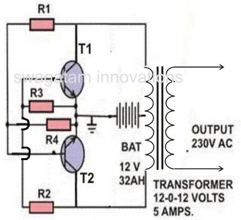
Well your search for such a circuit ends here. The circuit of an inverter described here is perhaps the smallest as far its component count goes yet is powerful enough to fulfill most of your requirements.
Construction Procedure
To begin with, first make sure to have proper heatsinks for the two 2N3055 transistors. It can be fabricated in the following manner:
- Cut two sheets of aluminum of 6/4 inches each.
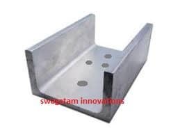
- Bend one end of the sheet as shown in the diagram. Drill appropriate sized holes on to the bends so that it can be clamped firmly to the metal cabinet.
- If you find it difficult to make this heatsink you can simply purchase from your local electronic shop shown below:
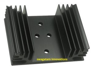
- Also drill holes for fitting of the power transistors. The holes are 3mm in diameter, TO-3 type of package size.
- Fix the transistors tightly on to the heatsinks with the help of nuts and bolts.
- Connect the resistors in a cross-coupled manner directly to the leads of the transistors as per the circuit diagram.
- Now join the heatsink, transistor, resistor assembly to the secondary winding of the transformer.
- Fix the whole circuit assembly along with the transformer inside a sturdy, well ventilated metal enclosure.
- Fit the output and input sockets, fuse holder etc. externally to the cabinet and connect them appropriately to the circuit assembly.
Once the above heatsink installation is over, you simply need to interconnect a few high watt resistors and the 2N3055 (on heatsink) with the selected transformer as given in the following diagram.
Complete Wiring Layout
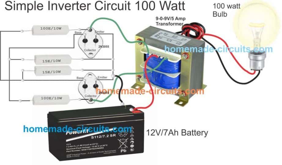
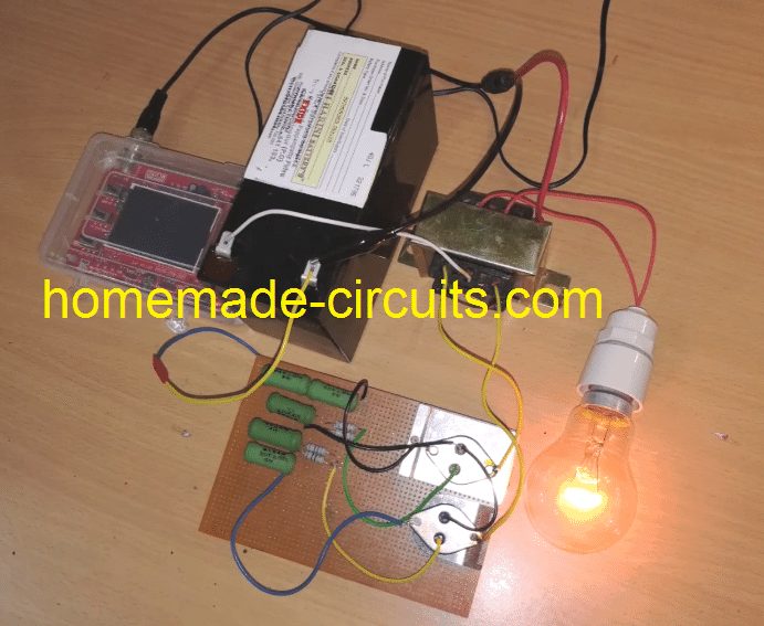
After the above wiring is completed, it's time to hook it up with a 12V 7Ah battery, with a 60 watt lamp attached at the transformer secondary. When switched ON the result would be an instant illumination of the load with an astonishing brightness.
Here the key element is the transformer, make sure the transformer is genuinely rated at 5 amp, otherwise you may find the output power a lot lesser than the expectation.
I can tell this from my experience, I built this unit twice, once when I was in college, and the second time recently in the year 2015. Although I was more experienced during the recent venture I could not get the awesome power that I had acquired from my previous unit. The reason was simple, the previous transformer was a robust custom built 9-0-9V 5 amp transformer, compared to the new one in which I had used probably a falsely rated 5 amp, which was actually only 3 amp with its output.
Parts List
You will require just the following few components for the construction:
- R1, R2= 100 OHMS./ 10 WATTS WIRE WOUND
- R3, R4= 15 OHMS/ 10 WATTS WIRE WOUND
- T1, T2 = 2N3055 POWER TRANSISTORS (MOTOROLA).
- TRANSFORMER= 9- 0- 9 VOLTS / 8 AMPS or 5 amps.
- AUTOMOBILE BATTERY= 12 VOLTS/ 10Ah
- ALUMINUM HEATSINK= CUT AS PER THE REQUIRED SIZE.
- VENTILATED METAL CABINET= AS PER THE SIZE OF THE WHOLE ASSEMBLY
Video Test Proof
How to Test it?
- The testing of this mini inverter is done in the following method:
- For testing purpose connect a 60 watt incandescent bulb to the output socket of the inverter.
- Next, connect a fully charged 12 V automobile battery to its supply terminals.
- The 60 watt bulb should immediately light up brightly, indicating that the inverter is functioning properly.
- This concludes the construction and the testing of the inverter circuit.
- I hope from the above discussions you must have clearly understood how to build an inverter which is not only simple to construct but also very affordable to each of you.
- It can be used to power small electrical appliances like soldering iron, CFL lights, small portable fans etc. The output power will lie in the vicinity of 70 watts and is load dependent.
- The efficiency of this inverter is around 75%. The unit may be connected to your vehicles battery itself when outdoors so that the trouble of carrying an extra battery is eliminated.
Circuit Operation
The functioning of this mini inverter circuit is rather unique and different from the normal inverters which involve discrete oscillator stage for powering the transistors.
However here the two sections or the two arms of the circuit operate in a regenerative manner. Its very simple and may be understood through the following points:
The two halves of the circuit no matter how much they are matched will always consist a slight imbalance in the parameters surrounding them, like the resistors, Hfe, transformer winding turns etc.
Due to this, both the halves are not able to conduct together at one instant.
Assume that the upper half transistors conduct first, obviously they will be getting their biasing voltage through the lower half winding of the transformer via R2.
However the moment they saturate and conduct fully, the entire battery voltage is pulled through their collectors to the ground.
This sucks-out dry any voltage through R2 to their base and they immediately stop conducting.
This gives an opportunity for the lower transistors to conduct and the cycle repeats.
The whole circuit thus starts to oscillate.
The base Emitter resistors are used to fix a particular threshold for their conduction to break, they help to fix a base biasing reference level.
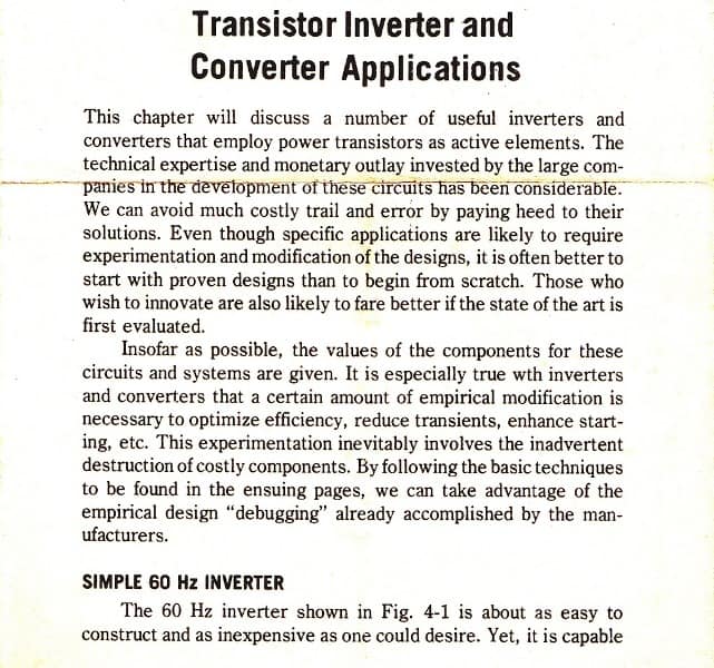
The above circuit was inspired from the following design by Motorola:
UPDATE: You may also want to try this: 50 watt Mini Inverter Circuit
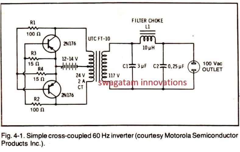
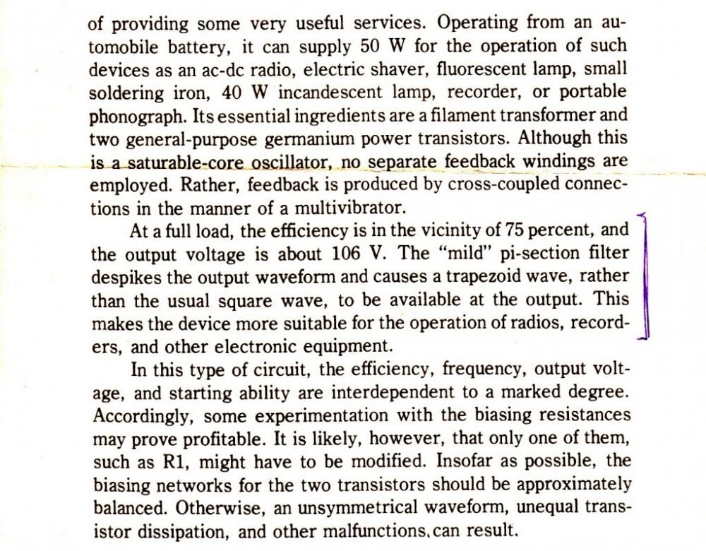
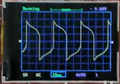
Output Waveform better than square wave (Reasonably suitable for all electronic appliances))
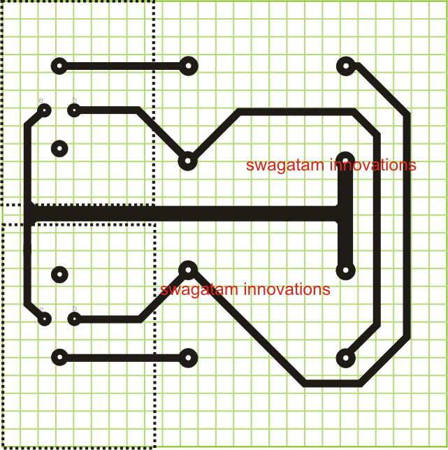
PCB Design for the above explained simple 2N3055 Inverter Circuit (Track Side Layout)


Need Help? Please Leave a Comment! We value your input—Kindly keep it relevant to the above topic!