These 7 inverter circuits might look simple with their designs, but are able to produce a reasonably high power output and an efficiency of around 75%. Learn how to build this cheap mini inverter and power small 220V or 120V appliances such drill machines, LED lamps, CFL lamps, hair dryer, mobile chargers, etc through a 12V 7 Ah battery.
What is a Simple Inverter
An inverter which uses minimum number of components for converting a 12 V DC to 230 V AC is called a simple inverter. A 12 V lead acid battery is the most standard form of battery which is used for operating such inverters.
Let's begin with the most simplest in the list which utilizes a couple of 2N3055 transistors and some resistors.
1) Simple Inverter Circuit using Cross Coupled Transistors
The article deals with the construction details of a mini inverter. Read to know regrading the construction procedure of a basic inverter which can provide reasonably good power output and yet is very affordable and sleek.
There may be a huge number of inverter circuits available over the internet and electronic magazines. But these circuits are often very complicated and hi-end type of inverters.
Thus we are left with no choice but just to wonder how to build power inverters that can be not only easy to build but also low cost and highly efficient in its working.
12v to 230v inverter circuit diagram
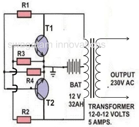
Well your search for such a circuit ends here. The circuit of an inverter described here is perhaps the smallest as far its component count goes yet is powerful enough to fulfill most of your requirements.
Construction Procedure
To begin with, first make sure to have proper heatsinks for the two 2N3055 transistors. It can be fabricated in the following manner:
- Cut two sheets of aluminum of 6/4 inches each.

- Bend one end of the sheet as shown in the diagram. Drill appropriate sized holes on to the bends so that it can be clamped firmly to the metal cabinet.
- If you find it difficult to make this heatsink you can simply purchase from your local electronic shop shown below:
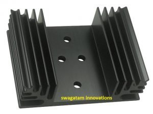
- Also drill holes for fitting of the power transistors. The holes are 3mm in diameter, TO-3 type of package size.
- Fix the transistors tightly on to the heatsinks with the help of nuts and bolts.
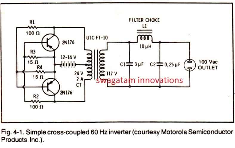
- Connect the resistors in a cross-coupled manner directly to the leads of the transistors as per the circuit diagram.
- Now join the heatsink, transistor, resistor assembly to the secondary winding of the transformer.
- Fix the whole circuit assembly along with the transformer inside a sturdy, well ventilated metal enclosure.
- Fit the output and input sockets, fuse holder etc. externally to the cabinet and connect them appropriately to the circuit assembly.
Once the above heatsink installation is over, you simply need to interconnect a few high watt resistors and the 2N3055 (on heatsink) with the selected transformer as given in the following diagram.
Complete Wiring Layout
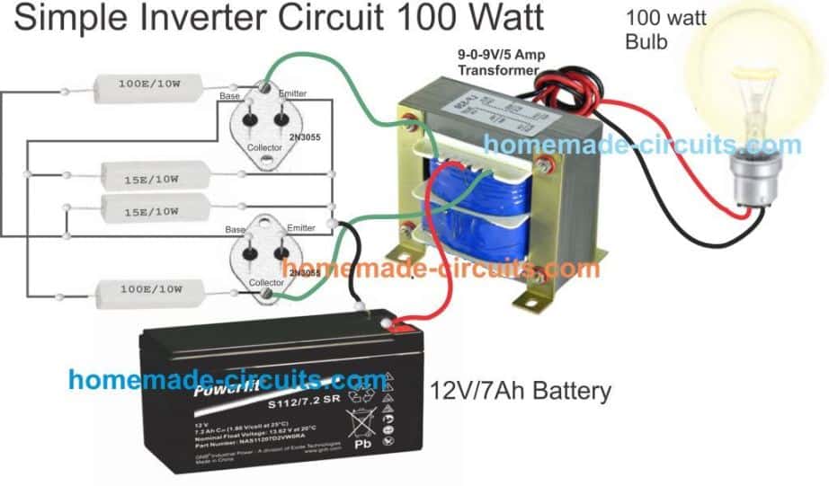
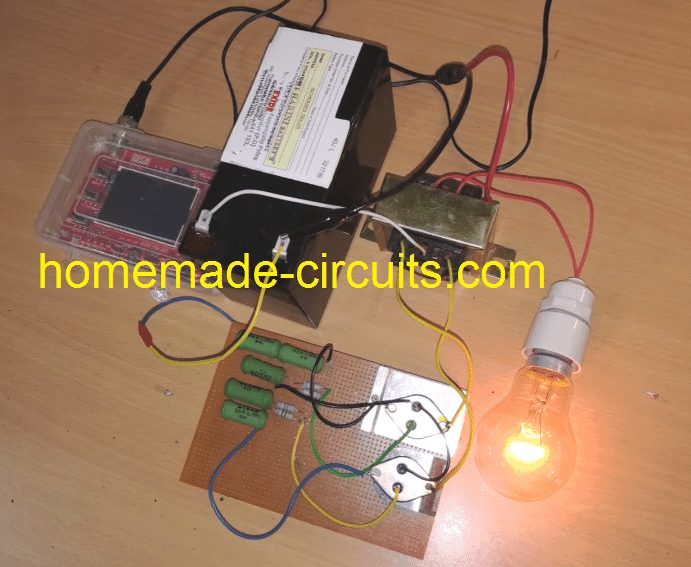
After the above wiring is completed, it's time to hook it up with a 12V 7Ah battery, with a 60 watt lamp attached at the transformer secondary. When switched ON the result would be an instant illumination of the load with an astonishing brightness.
Here the key element is the transformer, make sure the transformer is genuinely rated at 5 amp, otherwise you may find the output power a lot lesser than the expectation.
I can tell this from my experience, I built this unit twice, once when I was in college, and the second time recently in the year 2015. Although I was more experienced during the recent venture I could not get the awesome power that I had acquired from my previous unit. The reason was simple, the previous transformer was a robust custom built 9-0-9V 5 amp transformer, compared to the new one in which I had used probably a falsely rated 5 amp, which was actually only 3 amp with its output.
Parts List
You will require just the following few components for the construction:
- R1, R2= 100 OHMS./ 10 WATTS WIRE WOUND
- R3, R4= 15 OHMS/ 10 WATTS WIRE WOUND
- T1, T2 = 2N3055 POWER TRANSISTORS (MOTOROLA).
- TRANSFORMER= 9- 0- 9 VOLTS / 8 AMPS or 5 amps.
- AUTOMOBILE BATTERY= 12 VOLTS/ 10Ah
- ALUMINUM HEATSINK= CUT AS PER THE REQUIRED SIZE.
- VENTILATED METAL CABINET= AS PER THE SIZE OF THE WHOLE ASSEMBLY
Video Test Proof
How to Test it?
- The testing of this mini inverter is done in the following method:
- For testing purpose connect a 60 watt incandescent bulb to the output socket of the inverter.
- Next, connect a fully charged 12 V automobile battery to its supply terminals.
- The 60 watt bulb should immediately light up brightly, indicating that the inverter is functioning properly.
- This concludes the construction and the testing of the inverter circuit.
- I hope from the above discussions you must have clearly understood how to build an inverter which is not only simple to construct but also very affordable to each of you.
- It can be used to power small electrical appliances like soldering iron, CFL lights, small portable fans etc. The output power will lie in the vicinity of 70 watts and is load dependent.
- The efficiency of this inverter is around 75%. The unit may be connected to your vehicles battery itself when outdoors so that the trouble of carrying an extra battery is eliminated.
Circuit Operation
The functioning of this mini inverter circuit is rather unique and different from the normal inverters which involve discrete oscillator stage for powering the transistors.
However here the two sections or the two arms of the circuit operate in a regenerative manner. Its very simple and may be understood through the following points:
The two halves of the circuit no matter how much they are matched will always consist a slight imbalance in the parameters surrounding them, like the resistors, Hfe, transformer winding turns etc.
Due to this, both the halves are not able to conduct together at one instant.
Assume that the upper half transistors conduct first, obviously they will be getting their biasing voltage through the lower half winding of the transformer via R2.
However the moment they saturate and conduct fully, the entire battery voltage is pulled through their collectors to the ground.
This sucks-out dry any voltage through R2 to their base and they immediately stop conducting.
This gives an opportunity for the lower transistors to conduct and the cycle repeats.
The whole circuit thus starts to oscillate.
The base Emitter resistors are used to fix a particular threshold for their conduction to break, they help to fix a base biasing reference level.
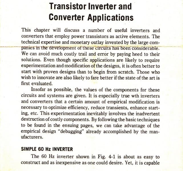
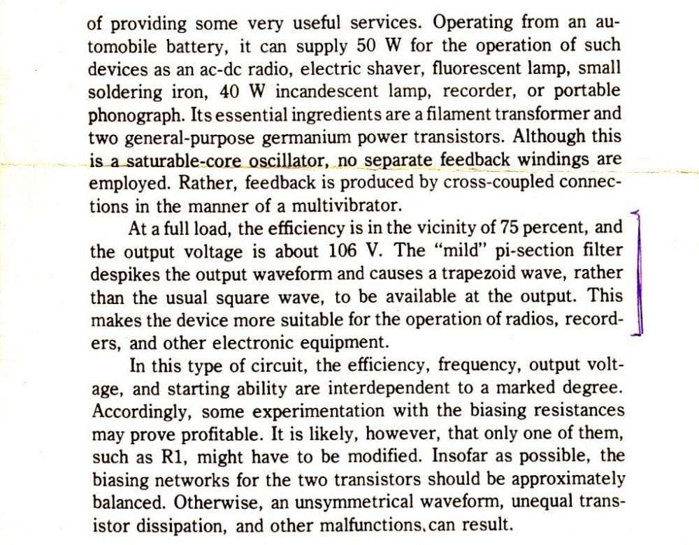
The above circuit was inspired from the following design by Motorola:
UPDATE: You may also want to try this: 50 watt Mini Inverter Circuit
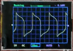
Output Waveform better than square wave (Reasonably suitable for all electronic appliances))
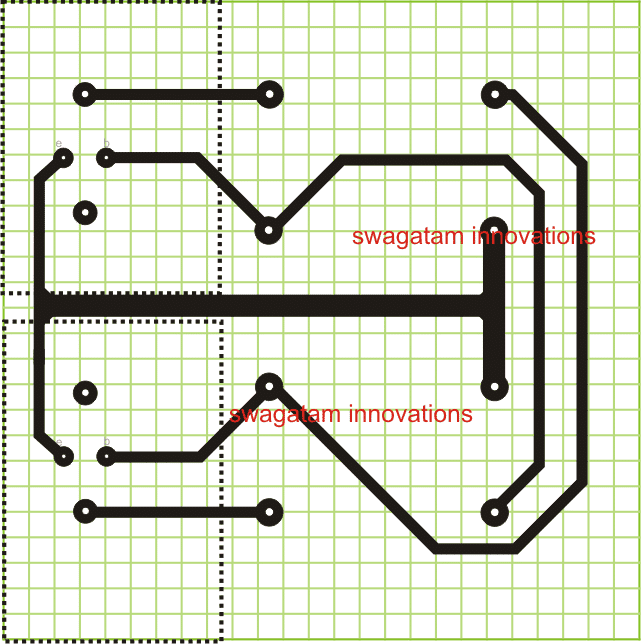
PCB Design for the above explained simple 2N3055 Inverter Circuit (Track Side Layout)
Cross Coupled MOSFET Inverter
The next design is a cross coupled simple MOSFET inverter circuit will be able to supply 220V/120V AC mains voltage or DC volts (with a rectifier and filter). The circuit is an easy to build inverter that will boost 12 or 14 volts to any level depending on the transformer secondary rating.
In this circuit, the primary and secondary of transformer T1 is a 12.6 V to 220 V step down transformer, connected in the reverse format.
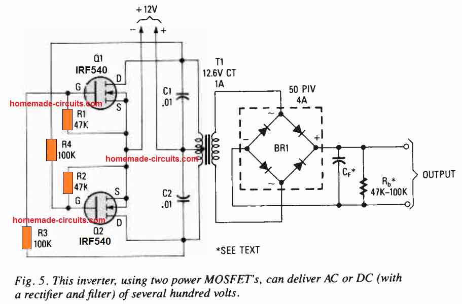
MOSFETs Q1 and Q2 can be any high power Nchannel FETs. Do not forget to apply heat sink to the MOSFETs Q1 and Q2. Capacitors C1 and C2 are positioned in order to suppress high voltage reverse spikes from the transformer. You can use any nearby value for the resistors R1-R4 having a tolerance of ± 20% to the shown values in the diagram.
The circuit is perfect to power a tube circuit, or it could be coupled with a step-up transformer to generate a spark gap, a Jacob's Ladder, or, by adjusting the frequency, it could be accustomed to energize a Tesla coil.
2) Using IC 4047
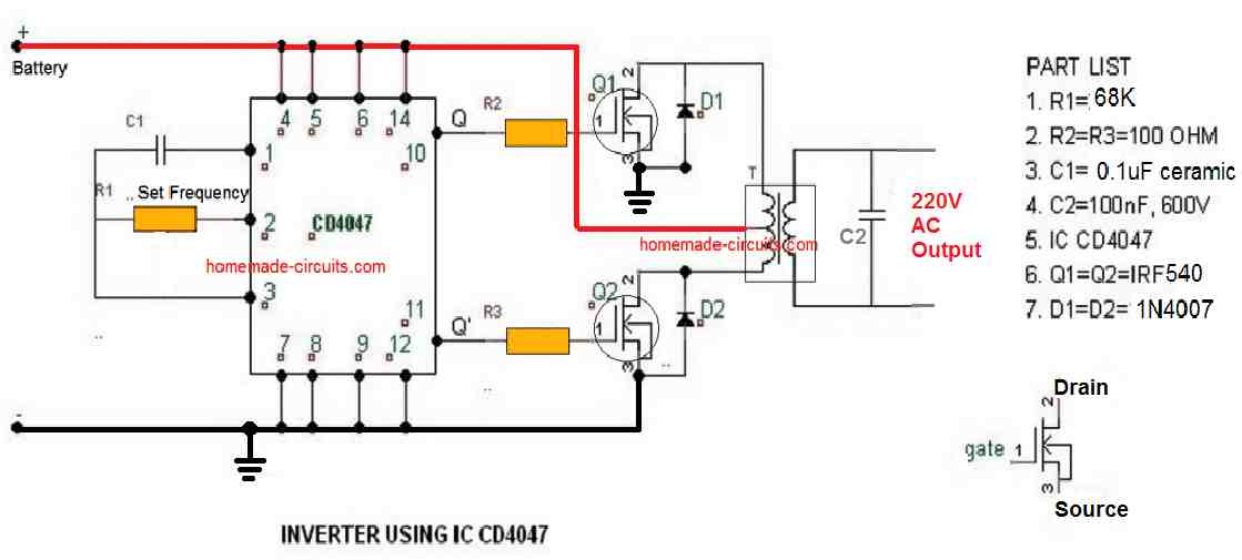
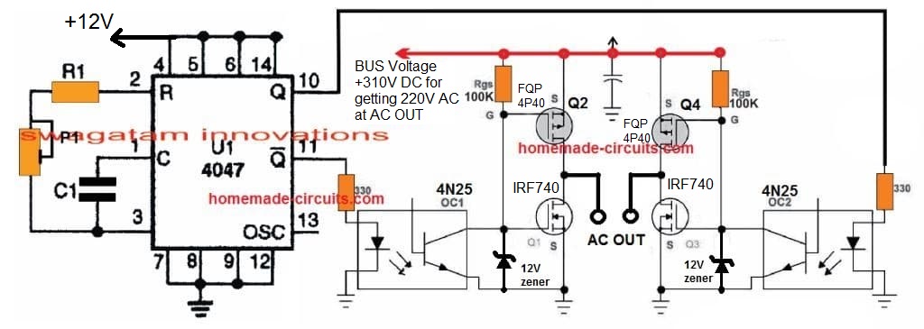
As shown above a simple yet useful little inverter can be built using just a single IC 4047. The IC 4047 is a versatile single IC oscillator, which will produce precise ON/OFF periods across its output pin#10 and pin#11. The frequency here could be determined by accurately calculating the resistor R1 and capacitor C1. These components determine the oscillation frequency at the output of the IC which in turn sets the output 220V AC frequency of this inverter circuit. It may set at 50Hz or 60Hz as per individual preference.
The battery, mosfet and the transformer can be modified or upgraded as per the required output power specification of the inverter.
For calculating the RC values, and the output frequency please refer to the datasheet of the IC
Video Test Results
3) Using IC 4049
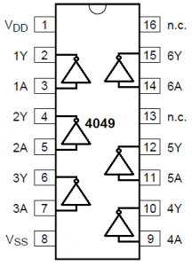
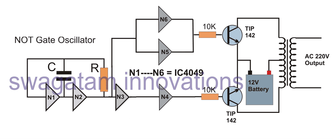

In this simple inverter circuit we use a single IC 4049 which includes 6 NOT gates or 6 inverters inside. In the diagram above N1----N6 signify the 6 gates which are configured as oscillator and buffer stages. The NOT gates N1 and N2 are basically used for the oscillator stage, the C and R can be selected and fixed for determining the 50Hz or 60 Hz frequency as per country specs
The remaining gates N3 to N6 are adjusted and configured as buffers and inverters so that the ultimate output results in producing alternating switching pulses for the power transistors. The configuration also ensures that no gates are left unused and idle, which may otherwise require their inputs to be terminated separately across a supply line.
The transformer and battery may be selected as per the power requirement or the load wattage specifications.
The output will be purely a square wave output.
Formula for calculating frequency is given as:
f = 1 /1.2RC,
where R will be in Ohms and F in Farads
4) Using IC 4093
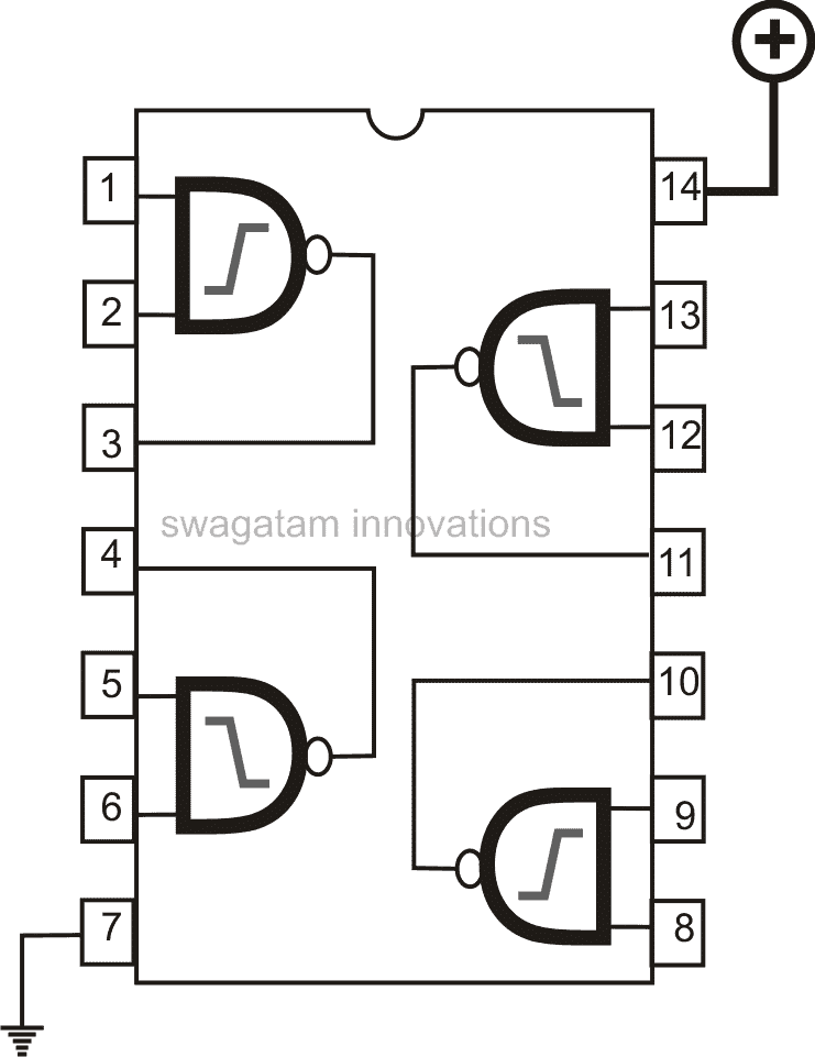
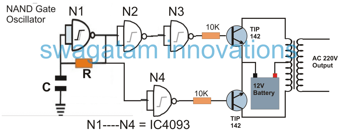
Quite similar to the previous NOT gate inveter, the NAND gate based simple inverter shown above can be built using a single 4093 IC. The gates N1 to N4 signify the 4 gates inside the IC 4093.
N1, is wired as an oscillator circuit, for generating the required 50 or 60Hz pulses. These are appropriately inverted and buffered using the remaining gates N2, N3, N4 in order to finally deliver the alternately switching frequency across the bases of the power BJTs, which in turn switch the power transformer at the supplied rate for generating the required 220V or 120V AC at the output.
Although any NAND gate IC would work here, using the IC 4093 is recommended since it features Schmidt trigger facility, which ensures a slight lag in switching and helps creating a kind of dead-time across the switching outputs, making sure that the power devices are never switched ON together even for a fraction of a second.
5) Another Simple NAND gate Inverter using MOSFETs
Another simple yet powerful inverter circuit design is explained in the following paragraphs which can be built by any electronic enthusiast and used for powering most of the household electrical appliances (resistive and SMPS loads).
The use of a couple of mosfets influences a powerful response from the circuit involving very few components, however the square wave configuration does limit the unit from quite a few useful applications.
Introduction
Calculating MOSFET parameters may seem to involve a few difficult steps, however by following the standard design enforcing these wonderful devices into action is definitely easy.
When we talk about inverter circuits involving power outputs, MOSFETs imperatively become a part of the design and also the main component of the configuration, especially at the driving output ends of the circuit.
Inverter circuits being the favorites with these devices, we would be discussing one such design incorporating MOSFETs for powering the output stage of the circuit.
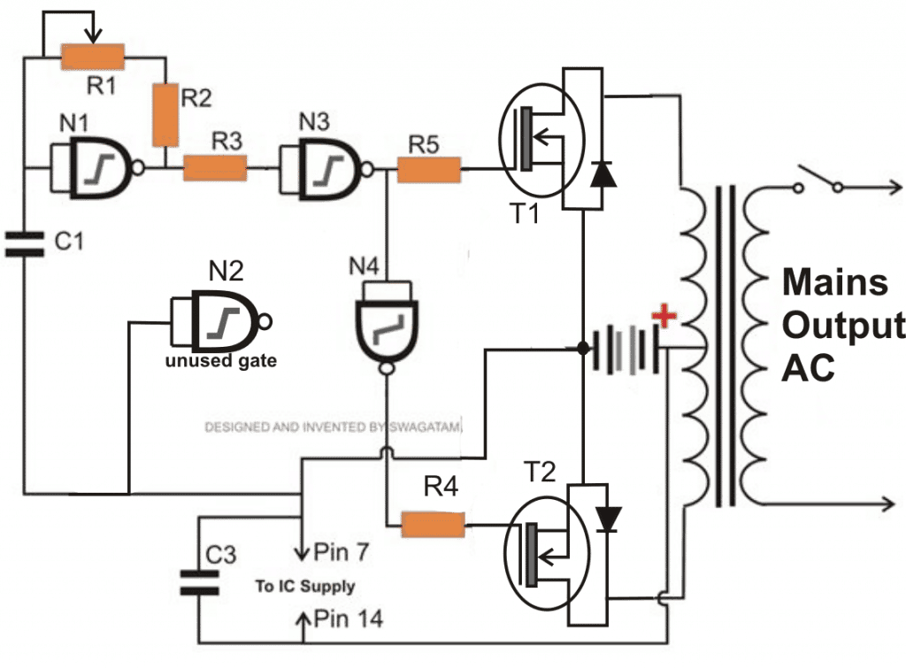
Referring to the diagram, we see a very basic inverter design involving a square wave oscillator stage, a buffer stage and the power output stage.
The use of a single IC for generating the required square waves and for buffering the pulses particularly makes the design easy to make, especially for the new electronic enthusiast.
Using IC 4093 NAND Gates for the Oscillator Circuit
The IC 4093 is a quad NAND gate Schmidt Trigger IC, a single NAND is wired up as an astable multivibrator for generating the base square pulses. The value of the resistor or the capacitor may be adjusted for acquiring either a 50 Hz or 60 Hz pulses. For 220 V applications 50 Hz option needs to be selected and a 60 Hz for the 120 V versions.
The output from the above oscillator stage is tied with a couple of more NAND gates used as buffers, whose outputs are ultimately terminated with the gate of the respective MOSFETs.
The two NAND gates are connected in series such that the two mosfets receive opposite logic levels alternately from the oscillator stage and switch the MOSFETs alternately for making the desired inductions in the input winding of the transformer.
Mosfet Switching
The above switching of the MOSFETs stuffs the entire battery current inside the relevant windings of the transformer, inducing an instant stepping up of the power at the opposite winding of the transformer where the output to the load is ultimately derived.
The MOSFETs are capable of handling more than 25 Amps of current and the range is pretty huge and therefore becomes suitable driving transformers of different power specs.
It’s just a matter of modifying the transformer and the battery for making inverters of different ranges with different power outputs.
Parts List for the above explained 150 watt inverter circuit diagram:
- R1 = 220K pot, needs to be set for acquiring the desired frequency output.
- R2, R3, R4, R5 = 1K,
- T1, T2 = IRF540
- N1—N4 = IC 4093
- C1 = 0.01uF,
- C3 = 0.1uF
TR1 = 0-12V input winding, current = 15 Amp, output voltage as per the required specs
Formula for calculating frequency will be identical to the one described above for IC 4049.
f = 1 /1.2RC. where R = R1 set value, and C = C1
6) Using IC 4060
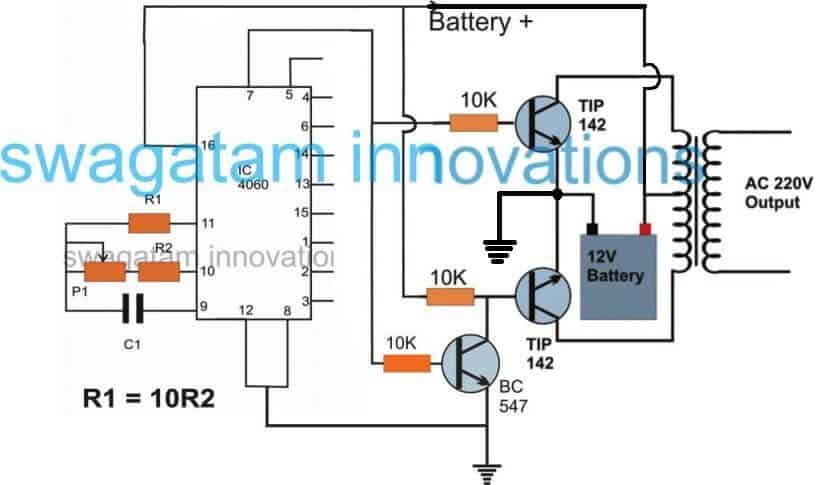
If you have a single 4060 IC in your electronic junk box, along with a transformer and a few power transistors, you are probably all set to create your simple power inverter circuit using these components. The basic design of the proposed IC 4060 based inverter circuit can be visualized in the above diagram. The concept is basically the same, we use the IC 4060 as an oscillator, and set its output to create alternately switching ON OFF pulses through an inverter BC547 transistors stage.
Just like IC 4047, the IC 4060 requires an external RC components for setting up its output frequency, however, the output from the IC 4060 are terminated into 10 individual pinouts in a specific order wherein the output generate frequency at a rate twice that of its preceding pinout.
Although you may find 10 separate outputs with a rate of 2X frequency rate across the IC output pinouts, we have selected the pin#7 since it delivers the fastest frequency rate among the rest and therefore may fulfil this using standard components for the RC network, which may be easily available to you no matter in which part of the globe you are situated in.
For calculating the RC values for R2 +P1 and C1 and the frequency you can use the formula as described below:
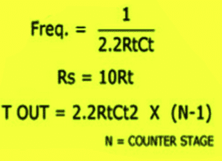
Or another way is through the following formula:
f(osc) = 1 / 2.3 x Rt x Ct
Rt is in Ohms, Ct in Farads
More info can be obtained from this article
Here's yet another cool DIY inverter idea which is extremely reliable and uses ordinary parts for accomplishing a high power inverter design, and can be upgraded to any desired power level.
I have explained more about this simple design
7) Simplest 100 Watt Inverter for the Newcomers
The circuit of a simple 100 watt inverter discussed in this article can be considered as the most efficient, reliable, easy to build and powerful inverter design. It will convert any 12V to 220V effectively using minimum components
Introduction
The idea was published many years back in one of the elecktor electronics magazines, I present it here so that you all can make and use this circuit for your personal applications. I have explained more.
The proposed simple 100 watt inverter circuit disign was published quite a long time ago in one of the elektor electronics magazines and according to me this circuit is one of the best inverter designs you can get.
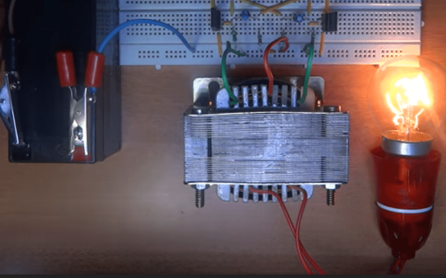
I consider it to be the best because the design is well balanced, well calculated, utilizes ordinary parts and if done everything correctly would start working instantly.
The efficiency of this design is in the vicinity of 85% that's good considering the simple format and low costs involved.
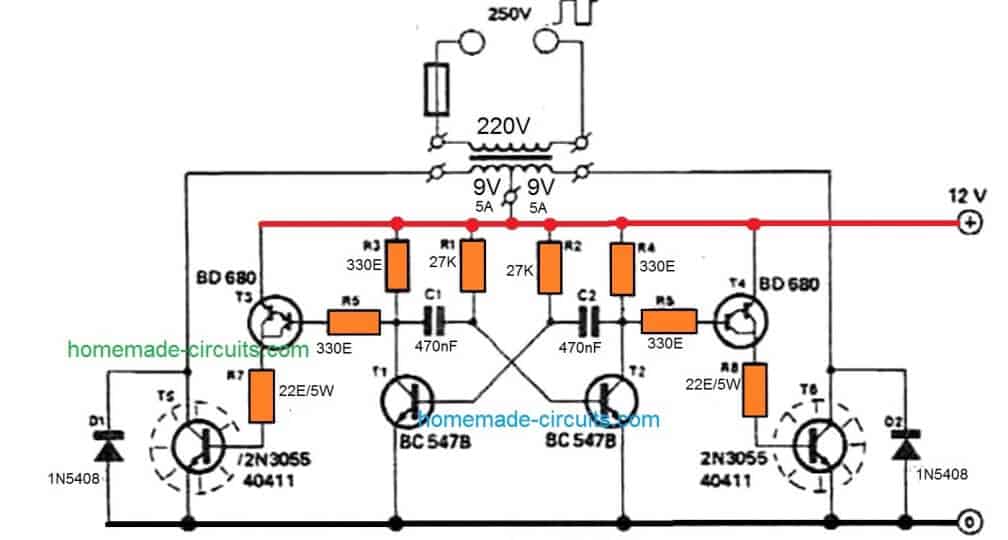
Using an Transistor Astable as the 50Hz Oscillator
Basically the whole design is built around an astable multivibrator stage, consisting of two low power general purpose transistors BC547 along with the associated parts consisting of two electrolytic capacitors and some resistors.
This stage is responsible for generating the basic 50 Hz pulses required for initiating the inverter operations.
The above signals are at low current levels and therefore requires to be lifted to some higher orders. This is done by the driver transistors BD680, which are Darlington by nature.
These transistors receive the low power 50 Hz signals from the BC547 transistor stages and lift them at higher current levels so that it can be fed to the output transistors.
The output transistors are a pair of 2N3055 which receive an amplified current drive at their bases from the above driver stage.
2N3055 Transistors as the Power Stage
The 2N3055 transistors thus are also driven at high saturation and high current levels which gets pumped into the relevant transformer windings alternately, and converted into the required 220V AC volts at the secondary of the transformer.
Parts List for the above explained simple 100 watt inverter circuit
- R1,R2 = 27K, 1/4 watt 5%
- R3,R4,R5,R6 = 330 OHMS, 1/4 watt 5%
- R7,R8 = 22 OHMS, 5 WATT WIRE WOUND TYPE
- C1,C2 = 470nF
- T1,T2 = BC547,
- T3,T4 = BD680, OR TIP127
- T5,T6 = 2N3055,
- D1,D2 = 1N5402
- TRANSFORMER = 9-0-9V, 5 AMP
- BATTERY = 12V,26AH,
Heatsink for the T3/T4, and T5/T6
Specifications:
- Power Output: 100 watts if single 2n3055 transistors are used on each channels.
- Frequency: 50 Hz, Square Wave,
- Input Voltage: 12V @ 5 Amps for 100 Watts,
- Output Volts: 220V or 120V(with some adjustments)
From the above discussion you might be feeling thoroughly enlightened regarding how to build these 7 simple inverter circuits, by configuring a given basic oscillator circuit with a BJT stage and a transformer, and by incorporating very ordinary parts which may be already existing with you or accessible by salvaging an old assembled PC board.
How to Calculate the Resistors and Capacitors for 50 Hz or 60 Hz Frequencies
In this transistor based inverter circuit, the oscillator design is built using a transistorized astable circuit.
Basically the resistors and capacitors associated with the bases of the transistors determine the frequency of the output. Although these are correctly calculated to produce approximately 50 Hz frequency, if you are further interested to tweak the output frequency as per own preference you can easily do so by calculating them through this Transistor Astable Multivibrator Calculator.
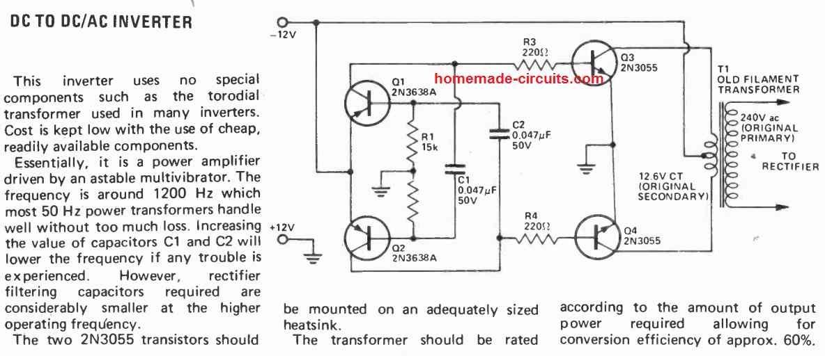
Another Simple Transistorized DC to AC Inverter Circuit
Q1 and Q2 can be any small signal PNP transistor such as BC557.
Universal Push-Pull Module
If you are interested to achieve a more compact an efficient design using a simple a 2 wire transformer push pull configuration, then you can try the following couple of concepts
The first one below uses the IC 4047, along with a couple of p channel and n channel MOSFETs:
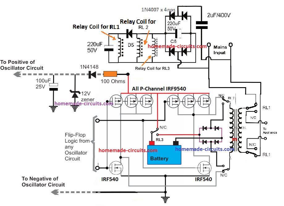
If you wish to employ some other oscillator stage as per your preference, in that case you can apply the following universal design.
This will allow you to integrate any desired oscillator stage and get the required 220 V push pull output.
Moreover it also has an integrated auto-changeover battery charger stage.
Advantages of Simple Push-Pull Inverter
The main advantages of this universal push-pull inverter design are:
- It uses a 2 wire transformer, which makes the design highly efficient, in terms of size and power output.
- It incorporates a changeover with battery charger, which charges the battery when the mains is present, and during a mains failure changes over to inverter mode using the same battery to produce the intended 220 V from the battery.
- It uses ordinary p-channel and N-channel MOSFETs without any complex circuitry.
- It is cheaper to build and more efficient than the center tap counterpart.
SCR Inverter
The following inverter circuit uses SCRs instead of transistors and thus allows even higher power output with a simple configuration.
The oscillation is triggered by a pair of UJTs, which ensure accurate frequency control , and also facilitates the adjustment of the frequency across the two SCRs
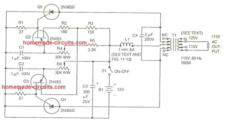
The transformer can be be any ordinary iron core 9-0-9 V to 220 V or 120 V step down transformer, connected in the reverse order.
For the Advanced Users
The above explained were a few straightforward inverter circuit designs, however if you think these are pretty ordinary for you, you can always explore more advanced designs which are included in this website. Here are a few more links for your reference:
More Inverter Projects for You with Full online Help!


Questions & Answers
hello sir how can I intergrate Ics sg3524 and using ir2110 as a MOSFET driver thanks
yes that’s possible
please help me with its circuit I want to setup one thanks
Hello I want to know which of all the inverters published on this site is better for devices such as smart tv, led tv, pc, and notebook .. Thank you very much. From Buenos Aires Argentina.
yes it can be used for all SMPS based appliances.
Hello, sir, thanks for the reply, but which one of all …
All of them can be used.
Thank you very much for your quick reply. My question is for the type of wave … I just wanted to know if they are safe for last generation devices … Thank you very much from Buenos Aires Argentina.
Any sinewave or modified sinewave inverter will be be good. But any 250V square wave inverter will also work because all the mentioned appliances are SMPS based and therefore will ultimately convert the AC into DC regardless of the waveform.
Thank you very much for your quick reply. That’s what I wanted to know. Thank you very much, you are a genius. Greetings from Buenos Aires, Argentina
You are most welcome Carlos!
Sir.
Those are good and interesting projects and i must say that i appreciate it and all of your circuits have been working well with me and also improving on my studies…
but i must say i am sorry for asking this favor here….
Sir do you have any project for car theft?? i dont mean car alarm, if i set the gadget on, the car works on a timer, if someone takes off with the car, at certain distance the car automatically stop moving such like engine gets stoped or battery cutts off, if also a schematic that can work like GSM will also be appreciated…
thanks for understanding and i will be looking forward to be reading from you again.
Nkwenti.
Hi Nkwenti, GSM may not be required for this simple application, it can be done with a small timer circuit integrated with the ignition system. However how do you expect the theft to happen, is it by manipulating the ignition wires or by stealing the ignition keys or through duplicating the keys..because the circuit design will depend on how it is triggered.
Sir all i wanted was a simple schematic that can be adjusted to indicate car speed step by step and then from that step by step i can do additions to it to stop or quench the car engine… where i am i do not fine audinor’s so a schematic that is not that complicated is what i am seeking for.
thanks for your reply sir.
nkwenti, please type tachometer in the search box on top right you will be able to find the required design.
Sir can i replace the 2n3055 with TIP142?
TIP142 is a Darlington transistor so I am not sure how it might react, but there’s no harm in trying. I would recommend TIP35 instead
ok sir… i will try TIP35 and also the darlington and give you my feedback… thanks for your help and guide… youre truly a teacher.
you are welcome nkwenti!
you also sir…. well the reason why i ask if i can use TIP35 was because i came accros this circuit from a website which had your labels so is this a good working circuit? then i was wondering why 3kva will run only with 12vdc instead of at least 24vdc.
here is the link.
2.bp.blogspot.com/-OV6ZWLz_JW0/UmjW3hdGB6I/AAAAAAAAFjk/AQTrzhS3gGE/s1600/3kva+inverter+circuit.png
This circuit was copied by many other websites. You can find this circuit and even better ones under this category:
https://www.homemade-circuits.com/category/dc-to-ac-power-converters/
it is a good circuit but won’t produce perfect sine wave, to get perfect sinewave you will SPWM instead of normal PWM.
output wattage depends on the battery specs, transformer specs and mosfet specs…..which can be easily modified and upgraded as per user preference.
Mr swagatam. Good day.. let me ask you again. I have inverter refrigerator but the board is dead. Can I direct it by using a simple circuit design? The main supply is 230 single phase AC mains and the output is 330 dc 3 phase. Thanks mr Swagatam.
Hello mark, do you want to discard the existing board and replace it with a new circuit? In that case you can specify the remaining things from the inverter which you want to include in the system, and specify their specifications, I may try to help!
Hi Swag,
aim looking for a 12v to 19.5 3.5A DC Dc inverter. do you have it any such in inverter circuit?
Regards.
Hi Paaker, you can try the following concept
https://www.homemade-circuits.com/12v-car-laptop-charger-circuit-using/
Thanks Swag. this is what aim looking for.
by the way this circuit aim going to power up a LCD TV not for charger. it can be use as power supply TV right?
Regards.
Hi Paker, yes it can be used for the said purpose, but the coil and the switching frequency will need to optimized correctly for getting the intended results.
The coil wire dimensions could be modified for achieving higher current outputs.
Sir good morning!! can i use 1 amp trafo and smaller transistor like tip 31? ill use it with 3 to 7 watt bulb.
Hi Jindro, yes you can do that…
Helo sir, pls I need more light on inverter transformer winding…
Am just confused…
I want to know how to wind inverters transformer of different capacities.
But my concern now is how to choose or know the :
=> swg for any inverter transformer capacity.
=>size of lamination core ,
=>related calculation for each capacity before winding…
=> how to know or determine the required voltage at the primary like 230,220 volt etc
I want to do inverter of different capacities and I don’t want to make mistakes with the transformer winding…
Hello Akinbi,
you can refer to the following article:
https://www.homemade-circuits.com/how-to-design-your-own-inverter/
although the max capacity will be 10 amps only.
Hie sir I’m new in electronics . Can you help me on the difference between square wave and sine wave
Hi Binus, if you switch ON and OFF a 12V supply the output will be in the form of a square wave because the output suddenly rises to 12V and then suddenly drops 0V, but if you do the same in such a way that the output slowly rises from 0V to 12V and then slowly drops from 12V to 0V then it will be in the form of a sine wave.
Helo sir, help me on how a capacitor is said to be a dc blocker and ac bypass whilst it is found in some dc powered circuits
Binus, all capacitors have this property. They block DC because DC forces a capacitor to charge in one direction only, and with no return path to discharge the capacitor blocks any further entry of the DC. Whereas an AC being alternating current provides the capacitor a discharge path on each cycle or pulse, thus enabling its continued passage for the subsequent cycles.
Thanks sir I understand now
Is it somehow possible to achieve with easy means, to get out of my 4 solar panels (4×34=136VDC)
the same Voltage but AC, to power my fridge (100W)?
I only find circuits with transformation from lower Voltage.
Snote
You will need an inverter circuit for this, probably a sinewave inverter since a refrigerator is involved. You may need one of these:
https://www.homemade-circuits.com/2017/10/5kva-transformerless-inverter-circuit.html
I am sorry there’s no easy way of implementing it.
Thanks for your reply. Apprechiate a lot.
But this looks like too much for me. I will stay with the
SMPS and the phone and computer. For the fridge I have to search for another solution…
Snote
Sure, no problems!
Can I use a 12v 30A car fuse for my solar panels?
I have 8 panels a 250W with 34V each.
I would connect 2 strings of 4 panels in series.
So I got 136V and 2000W = 14A.
Is this right?
When you connect the panels in series the watt will remain the same as for a single panel. So the total current will be 7 amp (@136V). The fuse should be also rated at this same value
Hi Sir Swag, can i use a rechargeable 12v9ah silicon gel type battery on the above last circuit, my load is a 20w LED bulb and/or a small fan (during power outage in my place)?
Hi Amor, yes no problem, you can use it.
Hi Sir Swag, i’ve built the last circuit above successfully but in less down an hour my new fully charged 12v 7Ah battery drops to 10v so fast and the 2n3055 getting too hot to touch, my heatsink is 4inch L and 1.5inch W is this too small?
Hi Amor, what is the load that your using, how much is its rating in watts?
my load was just a 2w LED bulb
then I think your circuit has some problems, cut the base of 2N3055 and check if it still gets hot or not?
Sir, after disconnecting both base of two 2n3055 then both remain cool nothing happen, battery stays at 13v
do you thinks there is a wrong connection or grounded even i made to lit a bulb?
Hi Amor, I think there could be problem with your transformer. Check the current by keeping ammeter in series with the battery positive, with load and without load.
Hi Sir Swag, the current in series with battery positive is 2.57amp stable without load and 2.33amp with a 1.5w led bulb and its dropping every minute. my trafo is a 9-0-9/0-210-220 6amp.
Hi Amor, that looks too high. It means even without a load your inverter is wasting 2 x 12 = 24 watts? There’s certainly something wrong. Make sure your IC is generating the required frequency and the mosfets are actually good.
Hi Sir Swag, do you think my trafo is causing why its consuming too much current even without load? because i’m using a step-down trafo instead of a step-up? i already replace the entire circuit and the result is the same. should i use a step-up trafo?
Hi amor, step up, and step down transformers are one and the same. When you use it with a AC mains it becomes step down and when you use it with an inverter the same trafo becomes step up.
you can perform one more check. Remove the mosfet gate connections from the IC, and connect them to the ground line. Now check the current consumption, If it’s zero then the culprit is the transformer, not the mosfets.
In that case you may have to replace the transformer with a new one.
Thank you Sir, i just thought step up and step down trafo is somehow different in windings of primary and secondary coil. anyways Sir what i’m building is your last circuit above using 2n3055 and TIP127 not the one using IC and mosfet Thanks.
Thanks Amor, in that case disconnect the base of the 2N3055 and connect them to ground for the mentioned verification
Hello sir.. How are u.. Sir one question about your second cricuit diagram where cd4047 ic used.. Problem coming from my cricuit is that when i connect the 7-0-7 5amp transformer to the two terminal of cricuit then my mosfet (irfz44n) is heated and i connect load to like 100w bulb then the mosfet will excess heat and bulb is not glow… What behind reason for this i cant understand.. So please help me sir..
Apurva, if your mosfet is heating up without load then either your IC is faulty or mosfets are faulty, or there could be some other connection fault.
first make sure the mosfets do not heat up without load. And If on load it is heating up then you must attach a heatsiink with the mosfets
Hello sir one problem is also occur. the ic will be damaged now when we give the load on transformer then mosfet will heat after that the ic will be damaged.. I check it now.. I purchased new ic it is also damaged… All connection will be correct i used 104 16v ceramic capictor, 100ohm 1/2watt resistance. All components connected properly sir..why it occurred i cant understand..
Did you connect D1, D2 across the mosfets?
Yes sir i used in4007diode on both side mosfet..
Then there could be some other fault in your circuit, or may be the mosfets are itself faulty. Is your transformer making slow buzzing sound when switched ON?
Yes Sir…. But when i connect 100w bulb then the sound will be stop and mosfet will now heating start..
solder the transformer wire directly to the bulb ends. Do this first then touch the battery positive with the inverter positive and see what happens.
You can also do this with a 40 watt bulb first and check the results
Sir i made this transformer by own hand i used 18swg wire in secondary side means (7-0-7) side and 25 swg in primary side.. Can i used correct wire gauge for this transformer winding..??
Sorry, in that case I can’t help. Please buy a good quality readymade transformer for getting the expected results!
Hi sir, can you help.
(a) With the aid of diagram explain how a magnetic hysteresis loop can be developed.
(b) Draw the hysterisis loop and label on it.
(c) Explain on these terms.
(i) magnetic saturation or saturation flux density.
(ii) reminant flux density.
(iii) coercive force.
Hi Binus, this explanation is already available online from other websites, with diagrams. You can easily check them out.
Sir can you provide a simple inverter circuit using hf transformer that can be found in mobile chargers…
Deepu, it is difficult to make inverter from a mobile charger transformer, even we if succeed in making the output power will be very less.
Sir, i have a 1080p mini wifi camera which operates on battery, can this wifi camera be operated on ac, if this is possible can you help me..
Hi Rikseng, does it have a DC input socket, for an USB port? Otherwise it can be a little complex to implement an AC based operation.
Yes it has dc input socket and one usb cable is included with it.
Then you can use apply 5V to the socked through a readymade mains AC to 5 DC adapter, and operate wi-fi with an AC input
Hi sir swag,please i how can i recharge the battery used for the inverter without removing it?
Hi Abdur, you can try the following concept:
https://www.homemade-circuits.com/single-transformer-inverterchargerchang/
Hello Swag,i would like tu use an external clock on the CD4060 to produce a 200KHZ output the only problem is that my 4060 is unstable with a quartz of 4mhz or 12 mhz (i have repected the pf capacitor value!
thank you
Hello Mathieu, please refer to the last diagram from this article, and connect the crystal in the shown manner:
https://www.homemade-circuits.com/how-to-understand-ic-4060-pin-outs/
hi, would you do a 10 kw three phase full sinus inverter ? I’d appreciate it if you could share the circuit diagram.
plz tell me the cost of project. if possible individual cost of the components also attach with the components name.
Each of the projects will cost around 700/-INR to 800/-INR without cabinet and battery. The transformer is the costliest part and will cost around 500/-INR (9-0-9 / 5amp). The battery may also cost around 1000/- INR
Hi sir, please can you help me with post me your powerful inverter 2000w integrated battery charger circuit diagram. Thank you
Hi Saeed, you can try applying the last concept in the above article….
Hi , your program site is very useful and didactic.
Thank you!
Hello! I am trying to make my own 240v inverter to power solar panels for residential use. what size charge controller and inverter I do I need and I also need a wiring diagram to make the inverter itself. please if you could help. Thank you!!!
Hi, You can get all the details in the following post
https://www.homemade-circuits.com/how-to-calculate-and-match-solar-panel/
Thanks very much
Fully informative
100% sharing with no gaps
What about running your home with two darling transistors at 600v 80amp near 12000kw to 17000kw at 120/240v with an input from some solar high voltage source 600v combined with a a few 9 amp solar cells.
I’m building an inverter using a 555 time ic but the problem is that when I try to step up the voltage I can’t get any voltage at the secondary coil…what could be wrong. .?
Bonjour Monsieur,
I read with great interest your “7 very simple inverters”. I need such a simple inverter for modelism with the following requirement : going from 12 Vdc to 12Vac no more than 1A. I got a 6-0-6/12 transformer. What will be your recommendation in term of choice between your 7 solutions ?
Best regards
Claude
Thank you Claude, you can get 12V ac across the 0-12V winding of the transformer. So you can build any one of these inverters and get the 12v ac from the primary side of the transformer
sir, i have try to modify existing 12-0-12/ 220v transformer from old amplifier board. the steel bars are very rusty, i m tring to rewind secondary with this voltage 12-6-0-6-12 /220 for inverter. but i forget turn while re-winding .i get this voltage at secondary output 12-6-0-5.5-12 /220 . i want to use that 6-0-6/220v for inverter.
my question is that will inverter work in this 6.0-5.5 windings.
Shankar, yes it work but the output AC waveform will proportionately uneven across the positive/negative half cycles.
sir , how i can send you my circuits for conformation of working and errors.
this is a circuit from old dvd power supply https://drive.google.com/file/d/1-CJJvCDKoe8oHlkO9eRVo7vO_9ZPcRI0/view?usp=sharing
i want to make it 5v 2amp usb charger circuit from this ic.(switching buck regulator)
it uses la5752 ic and input 12v supply and output +12v ,-12v ,and 5v .
Hi Shankar, please check the datasheet of the IC, you will find a suitable circuit diagram in it which you can probably use for constructing the 5 V charger
Many thanks, sir for your blessing !
Claude
Hi Swagatam,
The transformer used in “UNIVERSAL PUSH PULL MOSFET MODULE WHICH WILL INTERFACE WITH ANY DESIRED OSCILLATOR CIRCUIT” is it a 12V/220V transformer?
Regards
Jan
Hi Jan, if a square wave output is required then battery and transformer can be of similar voltage rating, but if the input is PWM then the transformer voltage will need to be proportionately lower than the battery voltage
Hi Swagatam,
I will be using PWM from the Arduino. My situation is that I have a few 12/220v 5VA transformers in stock which I would like to use for this project. Could I perhaps overcome this problem by using a DC to DC 12V – 30V converter to step up the voltage to the transformer. Will this work?
Your advice will be much appreciated.
Regards
Jan