In this post I have explained how to make a 3 phase inverter circuit which can be used in conjunction with any ordinary single phase square wave inverter circuit. The circuit was requested by one of the interested readers of this blog.
UPDATE: Looking for an Arduino based design? You may find this one useful:
The 3 Phase Generator using IC 4035
The 3 phase inverter circuits explained in the subsequent sections of the article, will all basically need a good 3 phase generator circuit. One such good 3 phase generator circuit can be built using the IC 4035,. Let us understand how to do implement it with the following explanation:
This circuit creates 3 square wave outputs, each 120° out of phase, just like a 3-phase AC supply but in digital (square wave) form. It is good for testing 3-phase inverter circuits, BLDC motor drivers, or simulating 3-phase logic.
MAIN PARTS USED:
| Part | Function |
|---|---|
| IC 555 | Works like a clock – generates fast square pulses. |
| CD4035A | 4-bit shift register – shifts logic “1” and gives 3-phase signals. |
| MJE340 + Zener | Gives stable 12V to ICs even if input DC is high. |
| NOT gates (N1, N2) | Helps reset and invert signals properly. |
Full Circuit Diagram

HOW THIS THING WORKS, STEP-BY-STEP:
(1) Power Supply Side
- The top side of the circuit says “+12V to +100V DC” — this means input can be any voltage from 12V to 100V.
- That high voltage passes through a 10k, 1 watt resistor, then to the Zener diode (12V).
- The Zener clamps the voltage to exactly 12V, and the MJE340 transistor supplies regulated 12V to all ICs.
So no matter what voltage we feed (12V to 100V), the circuit ICs will only see 12V. Nice trick!
(2) 555 Timer Section
- The 555 is in astable mode means it keeps oscillating on its own, making square waves.
- The frequency is set by R1, R2, and C, this tells how fast the 3-phase signal rotates.
- Pin 3 of the 555 outputs these pulses, this goes into the clock pin of CD4035A.
- That pulse pushes the shift register forward each time, like "step forward" on each beat.
(3) CD4035 Shift Register Section
Now the magic happens here…
- CD4035 is a 4-bit shift register so each clock pulse pushes the logic “1” from Q1 → Q2 → Q3 → Q4 → repeat.
- But here only Q1, Q2, Q3 are used as outputs. These are taken as:
- Q1 = phase#1
- Q2 = phase#2 (inverted by N2 for better phase shift)
- Q3 = phase#3
Each of these are 120° apart from each other (as long as we consider each clock pulse = 120°).
- N1 is used for reset logic or pulse shaping (basic inverter from IC 4049).
- N2 inverts the second output so that the phase shift looks cleaner so Q1, !Q2, Q3 → gives better symmetry.
OUTPUT WAVEFORMS:
- All outputs are square waves.
- Frequency is same but each is delayed from the other by 120°.
- You get a digital-style 3-phase signal...
IMPORTANT POINTS:
- N1 and N2 are NOT gates, from IC 4049.
- You must pulse the SER input (pin 10) once at start (logic HIGH) or just connect it HIGH permanently.
- If nothing appears at output then check:
- 555 oscillation.
- Reset pin of CD4035 (must be LOW).
- Proper pull-ups on output lines.
The 3-Phase Full-Bridge Driver Stage
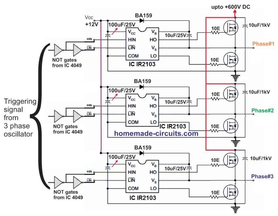
In the following 3 phase inverter diagram, remember the HIN, LIN pinouts must be fed with alternating pulses, which can be done using NOT gates from the IC 4049, or simply using a BJT BC547 stage.

In the above 3 phase generator circuit (second last diagram) using a sine wave doesn't make sense because the 4049 would ultimately convert it into square waves, and moreover the driver ICs in the last design employ digital ICs which will not respond to sine waves.
Therefore a better idea is to use a 3 phase square wave signal generator for feeding the last driver stage.
You may refer the article which explains how to make a 3 phase solar inverter circuit for understanding the 3 phase signal generator stage functioning and implementation details.
Using IC IR2103
A relatively simpler version of the above 3 phase inverter circuit can be studied below, using the IC IR2103 half bridge driver ICS. This version lacks the shut down feature, therefore if you do not wish to incorporate the shut down feature, you can try the following simpler design.
Simplifying the Above Designs
In the above explained 3-phase inverter circuit, the 3-phase generator stage looks unnecessarily complex, and therefore I decided to look for an alternative easier option for replacing this specific section.
After some searching I found the following interesting 3 phase generator circuit which looks pretty easy and and straightforward with its settings.
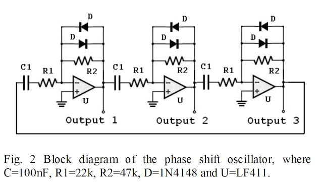
Therefore now you can simply replace the earlier explained IC 4047 and the opamp section entirely and integrate this design with HIN, LIN inputs f the 3 phase driver circuit.
But remember you will have to still use the N1----N6 gates between this new circuit and the full bridge driver circuit.
Making a Solar 3 Phase Inverter Circuit
So far we have learned how to make a basic 3 phase inverter circuit, now we'll see how a solar inverter with a 3 phase output can be built using very ordinary ICs and passive components.
The concept is basically the same, I have just changed the 3 phase generator stage for the application.
Inverter Basic Requirement
For acquiring a 3 phase AC output from any single phase or a DC source we would require three fundamental circuit stages:
- A 3 phase generator or processor circuit
- A 3 phase driver power stage circuit.
- A boost converter circuit
- Solar Panel (appropriately Rated)
To learn how to match a solar panel with battery and inverter, you can read the following tutorial:
Calculate solar Panels for Inverters
One good example may be studied in this article which explains a simple 3 phase inverter circuit
In the present design we too incorporate these three basic stages, let's first learn regarding the 3 phase generator processor circuit from the following discussion:
How it Works
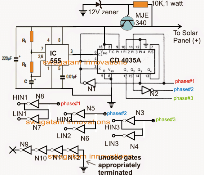
The diagram above shows the basic processor circuit which looks complex but actually it's not. The circuit is made up of three sections, the IC 555 which determines the 3 phase frequency (50 Hz or 60 Hz), the IC 4035 which splits the frequency into the required 3 phases separated by a phase angle of 120 degrees.
R1, R2 and C must be appropriately selected for acquiring a 50 Hz or 60 Hz frequency at 50% duty cycle.
8 numbers NOT gates from N3 to N8 can be seen incorporated simply for splitting the generated three phases into pairs of high and low logic outputs.
These NOT gates may be acquired from two 4049 ICs.
These pairs of high and low outputs across the shown NOT gates become essential for feeding our next 3 phase driver power stage.
The following explanation details the solar 3 phase power mosfet driver circuit
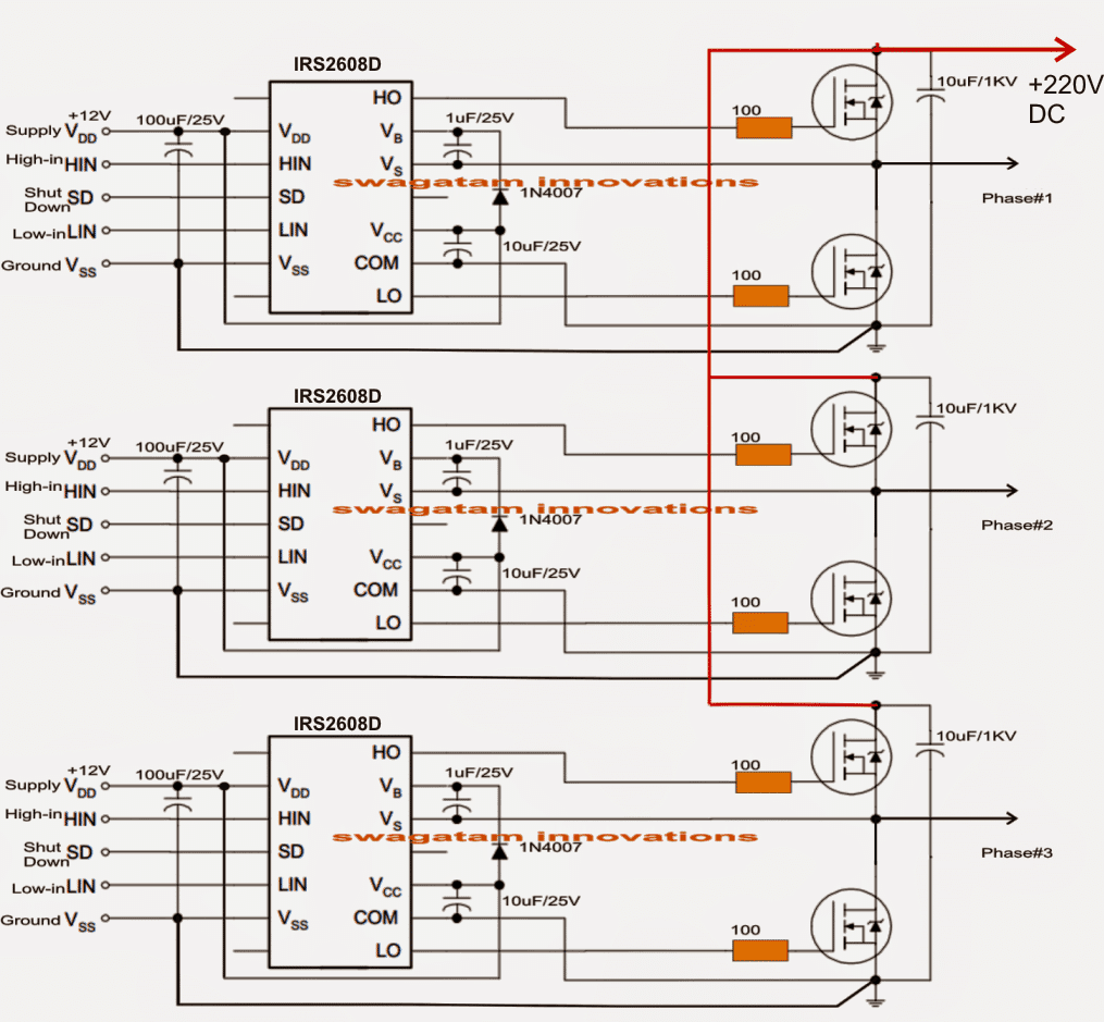
Note: The shut down pin must be connected to the ground line if not used, otherwise the circuit will not work
As may be seen in the above figure, this section is built across 3 separate half bridge driver ICs using IRS2608 which are specialized for driving high side and low side mosfet pairs.
The configuration looks quite straightforward, thanks to this highly sophisticated driver IC from International rectifier.
Each IC stage has its own HIN (high In) and LIN (low In) input pins and also their respective supply Vcc/ground pins.
All the Vcc are required to be joined together and connected with the 12V supply line of the first circuit (pin4/8 of IC555), so that all the circuit stages become accessible to the 12V supply derived from the solar panel.
Similarly all the ground pins and lines must be made into a common rail.
The HIN and LIN should be joined with the outputs generated from the NOT gates as specified in the second diagram.
The above arrangement takes care of the 3 phase processing and amplification, however since the 3 phase output should be at the mains level and a solar panel could be rated at a maximum of 60V, we must have an arrangement that would enable boosting this low 60 volts solar panel to the required 220V or 120V level.
Using IC 555 Based Flyback Buck/Boost Converter
This can be easily implemented through a simple 555 IC based boost converter circuit as may be studied below:
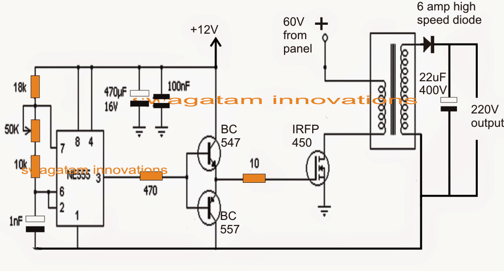
Again, the shown configuration of the 60V to 220V boost converter looks not so difficult, and can be constructed using very ordinary components.
The IC 555 is configured as an astable with a frequency of approximately 20 to 50 kHz. This frequency is fed to the gate of a switching mosfet via a push pull BJT stage.
The heart of the boost circuit is formed with the help of a compact ferrite core transformer which receives the driving frequency from the mosfet and converter the 60V input into the required 220V output.
This 220V DC is finally attached with the previously explained mosfet driver stage across the drains of the 3 phase mosfets for achieving the 220V 3 phase output.
The boost converter transformer can be built on any suitable EE core/bobbin assembly using 1mm 50 turns primary (two 0.5mm bifilar magnet wire in parallel), and secondary using o.5 mm magnet wire with 200 turns



Questions & Answers
Hi, Yes some of your points are correct, I'll reassess the above designs and look for appropriate solutions and update them soon..
hello brother, iam alek from indonesia,
iam very thankfully to you for the circuit diagram you uploaded,
iam working on methal machining, lathe,milling,etc ,
and nowdays,iam in situations which is need to build a simple converter,so i can run my 3phase 5HP lathe machine using single phase source,
i have read and learn all the circuit from you,but iam still confusing,
so with all regards please explained me about the circuit above,
mean,the whole complete circuit,the most simple 1…so i can build it my self,
please replay to my email
*subagyoss2015@gmail.com.
thank you
Hello Alek, I think you should try the following design instead:
https://www.homemade-circuits.com/how-to-convert-3-phase-ac-to-single/
i want to make sure that once i build the circuit its will work properly
so i can run my lathe machine using single phase power source, with no need to change the motor,
Done….I have updated the corrected versions, all the issues have been addressed correctly (hopefully).
Hi, maybe the High Frequency PWM signal from the 555 can be applied (through the diodes) to the outputs of the Hex Buffers, so it can quickly turn on/off the square wave signals.
No, that would cause oppostie responses for the NOT gate inputs….it would be more correct to connect the diodes with the shut down pins of the half bridge driver ICs, in fact diodes won't be required, pin#3 of the 555 astable could be directly integrated with the shut down pins of the driver ICs.
Hi i think this circuit will be good for me i would like use for 3 phase 400 volt asynchronus motor as generator for make induction in motor to generating electricity , my aim is from 12 DCvolt engine alternator who spin asynchronous motor convert to 12 v ac and with transformer make 400 v AC an this 400 ac to VDC I dont want use capacitors use between faces for that i would like electronic circuit i am little confuse thats pins SD where i should connect it ?
Hi, the above circuit is a 3 phase motor driver circuit from a single phase source…..so i cannot figure out how it would help your application.
SD should connected to positive for normal operation, if it's connected to ground the whole IC freezes.
it helps thanks
Sir im a electronic hobbiest i want a pwm inverter circuit with charger mains changeovr and low battery shutdown. THANK YOU. If u can send it to my e.mail vikramsha555@gmail.com
Vikram, if possible i'll to do it soon and post it to you.
I HAVE PROBLEM WITH A3(LM324)..
No Voltage on Gate 3….Output 0 Voltage with No Frequency…
On Gate 2- Voltage 6.56 with 50Hz
On Gate 4- Voltage -6.70 with 50Hz…
How can I solve This…..Advance Thnx
check input pin voltages of A3, if the voltage vary at the inputs then the output should also vary accordingly.
https://docs.google.com/file/d/0BzY3XDOhN0DWREswREtVQVJQalE/edit?usp=docslist_api
Watch This And Give me Answer For This Question
link is not opening, make the share option to "public"
https://www.dropbox.com/s/s59b0k3pkwlv8sp/3%2Bphase%2Bdriver%2Bsignal.png
did you make the circuit exactly as it's shown?
With the value of a few component i'm lost:
1). R1, P1 from the square wave generator?
2). rectifier bridge used for the supply of the motor
3). the driver transistors
Thanks
1) R1 and P1 will need to be determined by experimenting as per the desired output frequency.
2) rectifier diode current will depend on the amp specs of the motor.
3) you can use IRF840 for the mosfets.
Hello sir I want to design an 3ph inverter circuit using mosfet, so can you tell me what are the components specification for building this circuit .
Regards.
hello Arindam, you can go through the above published article for the details.
Can i use this circuit from 12 volt battery
yes will do…
hi sir,
i am going to do project under power electronics.i have to design 3-phase inverter.do i have to use IGBT driver for the circuit to work.
Hi senthil, yes using IGBTs will give better results and is recommended for a 3 phase inverter project
Can this circuits be modified to control a brushless 12 v motor
yes it can be, you can refer to the following article for more info:
https://www.homemade-circuits.com/2014/12/simple-3-phase-brushless-bldc-motor.html
Hi sir… I want to convert single phase 240v to 3 phase to drive half HP AC induction motor.. On which point i have to make changes
Hi Sagar, for your application you just have to use the last and the second last circuits, however the output will not be a sine wave, rather a square wave.
Pls what is the IC name of the Driver Circuit???
And value of R1 and P1
Hi sir, pls help me with the name of the IC in the driver circuit.
Hi Ambrose,
It's IR2103
Thank you very much sir.
you are welcome!!
Hello sir, do I need to connect more IGBTs or MOSFET in paralel to have more wattage To drive 6kw rated Motor??
yes, more devices in parallel would yield more equivalent power
Hello sir I've foud your post ver6 useful to me but a little confused you'd used 555 timer with first 4047 but in after corection you didn't add 555 timer…..why……thank again for such useful post
Thank you Muhammad, the 555 IC stage is for inserting PWM into the inverter in order to make the waveforms modified sine waves,
I did not include it in the revised diagram just to keep it simple, you can add it if you want across the HIN, LIN inputs of the driver IC.
Dear Sir,
Can only LM555 be used for PWM instead of 4047 at all. is the output of 4047 in sine form or square waves.
Dear Debu, yes IC 555 can be used instead of the shown 4047…good suggestion thanks!
4047 has a square wave output
Sir ow we convert 555 square output to Sine Wave
Muhammad, you can do it by inducing high frequency PWMs on the gates of the mosfets, please refer to the following article for more info:
https://www.homemade-circuits.com/2013/04/how-to-modify-square-wave-inverter-into.html
I am working on 3 phase inverter I have simulated above circuit in proteus.
i gave sine wave as input to lm 324 accordingly i get 3 phase voltage but when this output i given to ic4049 i didnt get any output.
try the 3 phase generator stage that's discussed in the following article:
https://www.homemade-circuits.com/2015/04/solar-3-phase-inverter-circuit.html
the first diagram
Hello sir,
in order to perform the three phase to 2 phase conversion by d-q transformation. then how it will be implemented in hardware. please do the needful. Can you provide me your email id??
Hello Neeta, I can't produce the calculation for the proposed circuit, since the design is a square wave inverter and the stages are all digital I don't think the dqo transformation would be relevant, even if it is so I have no idea how to do it for the presented design.
my email can be found in the contact page, at the top
Please sir
Where do I connect shutdown pin to??
shut down pin can be left unconnected, it must be used only if an automatic output correction is required or for any similar protection switching.
sir, i didn't get your email address.
it's given in the "contact" page.
OK you can see it below:
admin@162.240.8.81
Sir, If I need 3 phase inverter with 100Hz to the motor, how much the frequency input of my inverter?, I can imagine only if push pull inverter the input is 2X then output, isn't it?, thanks in advanced.
Ronald, which circuit are referring to? if it's the 4047 circuit above, then it should be 100Hz for your application.
plese give me all the values of these circuit.plz.. its my project
you can refer to this article for all the details:
https://www.homemade-circuits.com/2015/04/solar-3-phase-inverter-circuit.html
I have td310 can I use it as IGBT driver. can you help me with circuit diagram.
yes you can use it, the diagram is given in the datasheet of the IC
http://www.st.com/st-web-ui/static/active/en/resource/technical/document/datasheet/CD00000988.pdf
refer to page 6 for the complete circuit diagram.
dear sir
since i have put all the components to circuit but i am not getting the o/p as 12v y please suggest me wat values of components if put i would get 12v.
Hello Neha,
which circuit stage are you referring to? You'll need to go stage-wise and confirm the stages separately before connecting them together.
If you are finding the opamp 3-phase generator stage difficult, then you can try the following easier option:
https://www.homemade-circuits.com/2014/12/3-phase-signal-generator-using.html
Hello Sir,
What IC use for last circuit.
Hello Raj, It's IR2103 each
i thought the second to the last circuit is IR2110 which is 14pin DIP each, but now you said its IR2103 which is 8pin DIP, why
both have similar specs as far driving mosfet is concerned, but IR2110 has extra features in the form of a shut down pinout and current limiting pinout
so which one do you recommend among the two
depends whether you want to use those extra control features or not?
Hello Sir,
I was hoping to use this circuit power a 3phase 240vac motor from 12vdc. Will this circuit work for me? What sort of modifications will I need to make to change it from 330v to 240v?
Thank you for this guide, Super helpful.
Hello Jacob, the 12V can e used only for powering the IC, the motor voltage will need to be 220V in your case. which must be supplied at the drains of the mosfets. No other changes would be required
Thank you for your reply.
Can I use an Arduino instead of the IC you describe?
yes you can
Hello Sir,
Can I please get the simulation file of the 3-phase inverter ?
Can you tell me the range of this circuit
sir, i'm making a three phase inverter. So far I have made a simple gate driver circuit and I can switch each individual IGBT perfectly. But while making three legs of the inverter how should I connect them. Should I use bootstrap capacitor?
Amit, you will have to make an ordinary single phase inverter, then rectify its 330V AC to 330V DC and use it with the full bridge circuit for getting the required three phase output….the 3 phase from the mosfet/IGBT bridge can be directly used for operating the 3 phase load
sir i cannot find the updated version of the above topic. where is it?
the diagrams shown at the lower section of the article are all new updated diagrams….
HI.
i want to make three-phase inverter with output : 115v 400hz and input :28 vdc
can you help to to do this? what is the circuit?
You will need to boost the 28V to 150VDC and then feed to the mosfet drains as indicated in the above article.
Hi dear can i use sg3525a for generating pwm?thanks
yes that's possible!!
Hi Swagatam,
Thank you for your efforts!!
I would like to ask if there are any PCB designs for these circuits?
thanks Nikos, sorry I did not design the PCB for this.
SIR I WANT TO DEGINE 3PHASE INVERTER FOR 24 VOLT , 0.5 HP BLDC CAN YOU TELL ME COMPONENTS LIST
Im extremely thankful to u for sharing this over internet.. This ws very helpful for me to do my studies.. I have few doubts regarding this. Is it possible to change the duty ratio and the switching frequency as per our requirement? If yes can u plz explain in simple words? Thankyou
thank you, it is possible to inject PWM in the low side mosfet gates as indicated in the following example article:
https://www.homemade-circuits.com/2016/12/diesel-generator-rpm-controller-circuit.html
Sir since it is square wave,can we run a submersible three phase borewell pump safely?
Athri, it might create some noise, but that can be corrected by adding a capacitor across each of the wires and the "earthing" line.
Thank you sir for your information.
But Which capacitor shall I use and what should be it's rated voltage?
you can try 0.22uF/600V, and also try other higher or lower values and check which one gives the best results
Sir is there any options to get modified sine wave by injecting pwm pulses?
Athri, it is possible, you can inject the pwm to the low side mosfet gates for modifying the output…
Thank you sir for your valuable information
hi how are u?
i want to make 3phase inverter by avr. my question is how many spwm signal i need? 3 or 6?
sorry, for an AVR I cannot suggest since I have no idea how you would be coding it…
Dear sir thank you for your great service and let me know please how to use GIPN3H60 FOR THIS CIRCUIT can you post here or my email mptmsr@gmail.com its i found form barrier gate need to repair forward/rev
It's my pleasure Pathmasiri, that looks like a beautiful and very simple to implement IC, I'll definitely introduce this chip in my website soon, through a new article.
By the way you just have to apply an alternating 3 phase signal across the shown LIN HIN inputs of the IC, exactly as explained in the above article…..and you can get the results by directly connecting your motor across the shown outputs since it already incorporates built in mosfets.
Thanks tonn my pleasure i'll hope you'll post soon gipn3h60 three phase diagram
sure! you will see published very soon, please keep checking back!!
Thnks sir for this circuit ..
Respected sir .
Pls so components values .as capacitor c1 R etc.. and where connect the terminal SD(shut down) pls reply as soon as..
Thnks and regards
Thanks sir for this circuit..
Respected sir..
Sir pls show the values of components As c1 , R etc and where connect the terminal SD(shut down) pls reply as soon as.
Thanks and regards
Bhaskar,
you can use the second design from the following article for making the 3 phase signal generator, because using the 4047 and opamps looks unnecesarily complex
https://www.homemade-circuits.com/2016/12/3-phase-solar-submersible-pump-inverter.html
Bhaskar, The above explained 4047 IC and opamp based 3 phase generator circuit looks unnecessarily complex, instead you can use the second design which is shown in the following article
https://www.homemade-circuits.com/2016/12/3-phase-solar-submersible-pump-inverter.html
hello sir SPWM my project and load is 1 phase motor and 3 phase motor…..
and project is Analog base so pl help me this project
Hello Bhavya, you can try the concept which is explained in the above article, for the 3 phase generator you can use the last circuit using 3 opamps…if you have any specific questions you can feel free to ask them through comments.
sir pl provide your email id….i send my Doc file…
Sir i have using op amp for compare to sine wave and triangular wave…and than gate pluse are in mosfet circuit….and than V/F ratio find and load is motor joint…
so pl help me
Hi Bhayva, you can send it to
homemadecircuits
@ gmail.com
hai sir, i have done with first PWM circuit with IC 4047 ,555 IC and i used resistor Ra 100k , Rb 200k and capacitance C 10uf near 555IC and finally output is 280khz. i have no idea what exact to be use here .so plz help to know the exact value to that resistor and capacitor in order to get output in 50hz.
Hi Shivaji, you can check the last circuit from this article:
https://www.homemade-circuits.com/how-to-use-ic-555-for-generating-pwm/
hai sir,i have seen output frequency 70Khz to 1.07Mhz of first pwm ckt and even in that case i connected to 3 phase genarator ckt of first model . i dnt get any output from that ckt.
shivaji, this circuit is not for newcomers, you will require an advanced knowledge of electronics to understand and succeed with the above project.
hai sir, plz can know, what should be the output according to improved pwm stage circuit .
The output will be normal as you may expect from the inverter that is 220V or 330V as per the specs….the improved design will be easier to build and will give guaranteed results.
Good work Swaggatan
Hi, good website and lots of innovative ideas. My question is this, Is it possible to design a simple 3 phase inverter that produces true sinwave output? I have a few old 3 phase machines that I would like to use. I don’t need a varible speed design and the motors are about 1kw each. What are your thoughts? Many thanks, Chris.
Glad you liked the designs,
yes it can be designed and customized using the following concept
https://www.homemade-circuits.com/universal-esc-circuit-for-bldc-motors/
you can replace the IC 555 pwm stage with a SPWM stage and transform the design into a pure sine wave output
Thanks for the speedy reply, I’m new to all this so please except my apologies for my ignorance , but how is the negative cycle of the Sine wave generated ? Many thanks for your patience.
It is generated by the low side mosfets
Good day please can you give me a circuit that will convert 220vdc to 12vdc at 1amp maximum to be used in powering the
The PWM generator circuit
The 3 phase signal generator circuit
The mosfet driver circuit
thanks
Hi, why do you need 1 amp for this? 50mA would be enough.
Good day please what circuit will I now use to convert 220vdc to 12vdc
you can try the last circuit from this article
https://www.homemade-circuits.com/3v-5v-from-9v-using-diodes/
use MJE13005 for the transistor, 47K for the resistors, and also 47K for the preset…..use 2 watt resistors.
What I use In replace of ic 2103.
Any other name please say sir
type “3 phase driver IC” and search online, you may find many other alternatives…
For generations HIN And LIN
Can we use transistor in replace of 4049
you can do it, but make sure to add pull up resistors at the collectors.
Sir output of LM 324 pin no 7,8,14 give output to six mosfet
What next step I do for voltage 240v at the output of three phase.
Power driver is necessary for this ?please tell me about this power driver ic
Hi Abhishek, sorry what are you trying to make with the opamps? are you trying to make the 3-phase generator?…you will have to check/confirm each and every stage separately, very carefully and with full understanding otherwise you can never succeed…this project is for the experts who have advanced knowledge of electronics, so proceed with caution
Good morning, I’m sorry for the posting of the article. I have a question with this circuit, how can I reverse this engine?
for reversing the motor, you can reverse the 3 phase sequencing through a TPTT switch or 3 pole 3 way switch connected across the HIN, LIN inputs
Good morning, Mr. Swagatam, thanks for the help in the engine reversal !!
but I have another doubt I would use the circuit with a three-phase network could explain how the circuit would be because the three-phase simulator would be removed and would be only the ckt pwm and the high voltage
Good morning Bruno, you can remove the entire 3phase generator stage and feed the HIN and LIN with rectified DC from the available 3 phase supply.
you can use resistive divider network for dropping the high 3 phase signal into 12V low voltage 3 phase signal and feed them across the HIN LIN inputs.
Thank you master, see if you’re sure I’ll do it okay.
1 calculate the resistor oara the voltage drop from 120 vac to 12 dc
2 put a rectifier diode on the end of each phase then I’ll enter the gates of ci 4049 for the alteas and low entrances ok ??
That’s right Bruno, but after rectification to 12V DC the extra rectifier diodes will not be required.
make sure to have 3 DC inputs sequencing alternately as per the 3-phase signal
Good morning sir I doubt in the three-phase generator circuit I saw that it found a simpler circuit in its searches I would like to know where I would enter the pwm pulse generator made with c i 4047
I can use the original circuit that you did with the ci 324 it works correctly ???
Good Morning Bruno, the PWM pulse will need to be inserted to the low side mosfets, it cannot be inserted to the IC 4047 stage….first try the LM324 generator separately if you succeed then you can proceed.
sir, I have seen a new diagram that you have designed, you can see that you do not need the ci 4049 to make the high and low outputs in the inverter design. I’m going to try this new circuit. the lady changed the ci before was an ir2110 now I see an ir2103 has any difference between them tks
Lord I’m sorry for writing because I’m Brazilian and we talked through translation on LINE so there may be difficulty understanding the words okay good night
Bruno, It may work without 4049 but it is recommended for accurate functioning of the circuit, because the driver IC is a digital IC, therefore the input signals must be also perfectly digital or logical.
The two ICs are exactly similar, but IR2103 is the simpler version and it does not have the shut down pin, the IR2110 has the shut down pin option, so if you do not wish to include shut down feature, then IR203 can be used.
https://www.infineon.com/dgdl/ir2103.pdf?fileId=5546d462533600a4015355c7b54b166f
Dear sir, I have need a 24v dc to 400v ac 50 Hz 2kw inverter for induction motor. How possible to get it. There is a mosfet drive 3 phase inverter that you have given. May I use this circuit for my demand ? If possible, which quality mosfet need for output 400v ac / 2kw. Sir please help me. Thanks. Aristarcus.
Hi Aristarcus, yes you can use the circuit for driving any 3 phase motor, just make sure the mosfets are appropriately rated as per the motor ratings
Sir what i do
Power driver ic2103 and any driver ic
Are not available in the market
Sir please give any other ic solution for three phase inverter 12v dc to 240v AC
Abhishek, just Google “half bridge driver IC” you will be able to find many.
Sir
What is working of h bridge driver ic
After three phase generations stage
Why I can’t give these to mosfet
Please tell me sir and working of h bridge driver ic
The driver IC performs complex processing for activating the high side mosfets, necessary for operating a full bridge network…without these operations a full bridge cannot work
Can I use 33883 ic is a h-bridge driver ic
In respect of other half bridge driver ic
Please sir I am very upset
yes definitely you can use it….
Sir how connect this
HIN and LIN in which pin
Sir can you provide the diagram
So kind sir
Abhishek,
you will have to make a 3-phase generator circuit first and then feed the 3 phase signal to the HIN, LIN inputs of the IC.
Sir I’m already complete three phase signal generations stage
But problems sir how connect HIN and LIN in which pin of 33883ic
Because thise is the new ic
Only one ic use or three ic use or how is as full bridge driver
I am sorry, your IC is not a 3 phase driver, it is only a full-bridge driver IC, I mistakenly assumed it to be a 3 phase…if you are trying to search for 3 phase driver IC, then you must Google “3-phase driver IC”
By the way I had told you to search for a “half bridge driver IC” not full bridge IC…so please search for alternative “half bridge driver ICs” and then you can use 3 of these ICs to build a 3 phase inverter by integrating a 3 phase signals
hello can I use SG 3524 ic in the 3phase circuit with ir2110 can it work for me better thanks
sorry that may not be possible..
Hello this inverter how many watt?
The wattage can be any desired value depending on the rating of the mosfets and the input current
Dear Sir, I have a 5.5 kW 3 phase (400V 50 Hz) motor fitted on a machine that I need to use very few times a day for not more than 3 minutes at a time. I have to get this work done by outside persons as I can not get 3 phase to my working place and my power source is 30 Amp single phase 50 Hz 230 V or 12 V 100 Amp Hr battery. Please give me a simple and economical solution to construct a suitable circuit to run the 3 phase motor. Thank you
Dear Cassim, the last two circuits shown in the above article are the simplest and are compulsory for a 3 phase conversion. It cannot be more simple than this, sorry.
Dear Mr Swagatam – Thank you very much for your reply. I will follow the circuits and revert for further advice when necessary. Thank you once again – Cassim
You are welcome Cassim, wish you all the best!
Hello sir
I am trying to make a single phase to three phase inverter using pulse width modulation and mosfet switches on an H – bridge. I have a power circuit that i think will work but I am stuck on the control circuit that generate signals to control all six switches. May you please assist me with the code and a suitable microcontroller which is relatively cheap but suitable for a frequency of 50Hz for the output alternating current to operate at a power of 5kW. If you can also assist me with content which i can use to familiarise and understand what was in the code later when I have time I would be very grateful. You may also suggest a control circuit so I can work with what is best
Hello Morgan,
I think I already have one related article which you can refer to for the details:
https://www.homemade-circuits.com/arduino-3-phase-inverter-circuit-with-code/
Hello Swag can i put a CD4060 on pin 2 of the lm324 without pwm?
thank you
Hello Mathieu, Are you referring to the 3 phase generator diagram? pin2 of A1 does not required any PWM, it is simple square wave input.
Hi Swag,does a ir2103 can reproduce a sine wave ?
if i produce a sinewave with a pic16F can the ir2103 can transmit this sinewave for mosfetts drive?
thank you
Hi Mathieu, if you can create a pair of complementing SPWM and feed them across HIN and LIN of the IC then it can be used for driving the MOSFeTs with a sinewave output
Hi
I am trying to use generic Hoverboard motors on a wheel chair. Hoverboard main PCB uses its own IR sensor board as inputs. I would like to utilise a joystick for the motor operation. Can you suggest a simple method to achieve this?
Sorry, I have no idea about joystick control…
I truly appreciate this blog article.Much thanks again. Really Cool.
Hi
Can you please explain that in the 3 phase drive circuit what is the mosfet you have used after IR2103 and what is that 330v dc
Hi, You can use any MOSFET rated with VDs = 400 V and Current ID = 5 amps or as per the load specifications.
330V DC is the input voltage which will be converted to 220 V AC as the output.
Hi
Can I use this circuit for normal 12 v dc to 3 phase ac Inverter
You will have to first covert the 12V to 330V DC and then you can use it, or alternatively use a 3 phase 12V to 220V transformer with the MOSFETs.
thanks for the good work done sir.Please i want to control a 3-Phase motor with 72 volts dc.i want you to give me the componet list of the PWM using IC 4047 and also what is the number of the transister connected to ground. and if possible send me the full circuit connection of IC 4049 thanks
Thanks Addae, you can use the IR2103 IC based design, it should be quite sufficient for driving any 3 phase motor.
Thanks I want you to give me the value of R1 and C1 of the PWM circuit using 4047
Dear Sir,
My BMW N52 engine coolant water pump motor has its drive circuit packed up. Its a 3-phase 12V-AC and I need simple circuit to convert 12V car battery input power to 12V-AC. What is the simplest circuit? I need to use the motor to pump water elsewhere
Hi Collins, you can use any full bridge driver circuit using BJTs, or mosfets. Examples of full bridge diver can be seen in the following diagrams:
2 Simple Bidirectional Motor Controller Circuits Explored
Dear Sir,
My small 2kW genset has its inverter cooked. I have been able to convert its Delta winding low power 400V-AC 3-phase output to about 500V-DC. I need a simple steady inverter circuit to convert the 500VDC to about 230V-AC.
Would you have such a circuit?
Hi, thanks for your sharing. I think if we use ir2104 instead of ir2103 and 4049 will not be needed. Thank you in advance for your reply.
Hi, yes for IR2104, the 3 phase inputs can be directly configured with the IN pinout of the IC
Dear
I want complete one image file Simple Stable Regular Use Working Circuit Design for convert single phase 230v 50Hz Ac Supply to Three phase Phase to Phase Like R-Y, Y-B, B-R 415v AC 50Hz Supply With Load 1-AMP to 5AMP 3 Phase .
Thanks & Regards
Darpan Ghodasara
+919824549849
Hi Darpan, I don’t have this circuit with me at the moment, if I happen to get it, will inform you about the same…
i am confusing in pwm generator circuit where r1,p1,c1 what is the value of it
and 3 phase signal generator circuit where c1 =?
mosfet driver circuit what is the watt of 100ohm resister and which mosfet
and what is the value of ah battaery
can i use irf540 mosfet in this circuit and is it right one mosfet is n channel and another is p channel
plz help me this is my final year project
The formula is
f = 1/4.4RC
R = P1 + R1 and these should be in ohms.
C will be in farads
100 ohm is 1/4 watt
battery Ah and voltage will depend on the required inverter power output.
All mosfets are N channel, and its rating will again depend on the desired inverter power output
Hi Very interesting the 3 ph circuit .
I am thinking about driving a std 220v refrigeration compressor with this type of circuit .
Your thoughts on this application ?
Regards
Nico
Hi, thank you and glad you liked the post. I think fridge compressor require sine wave AC, so unless the above 3 phase inverter is converted to sine wave it can be unsafe to use.
4049ic connect
I want to achieve a 3 standard phase output(415v ) from 12v batteries. I understand how to go about this up until the mosfet drver where you fed in 330V dc into the mosfet .
How will i get my desired out voltage(not for motor control) using your mosfet driver configuration
You will get the 3 phase voltages across the 3 wires that are connected to the motor. If you feed 330V Dc to the mosfet drains, then the output wires from the mosfets will produce 330V AC 3 phase square wave.
Hi
there is a little difference in opinion. to obtain 220vac line to line you will need 311VDC bus & for 415V ac line to line you will need 650VDC bus.
Hi, the output AC from the bridge is a square wave not a sine wave, so its value will be equal to the DC input, according to me.
like it this idear l like learn form you but if are going teach me very well
Hi Swagatam.
Thank you very much for the detailed explanations of the 3-phase inverter designs shown here.
I was hoping to make enough sense out of this article to make an inverter for my specific need:
I need 115V 400Hz 3-phase with just some 200 – 400mA output. It would ideally have an input of 12VDC and be small. It is is to drive a vintage artificial horizon instrument out of a WW2 aircraft. It has 3 low power gyroscopes in it that require this voltage and frequency. It is for demonstration purposes, NOT for use in an aircraft. 🙂
Kind Regards,
Joe Hovel, Australia
Thank you Joe,
It is possible to get 115V, 400 mA 3-phase AC from the shown designs. You can try the IC IR2103 based design which appears to be a good option. However for getting 115V you will need to supply 115 DC across the drains of the mosfets. If you are intending to get the 115V from 12V then you will have to first boost the 12V to 115V through a boost converter circuit and then feed it across the mosfet drains.
the flyback buck/boost converter would usually have a snubber network across the transformer primary to absorb transients.
Hi Swagatam
Many thanks for all the interesting stuff on your site as its very helpful for a learner like me. As per an earlier request, I need a circuit to produce 115v 3 phase 400Hz to power a military artificial horizon using a 12v dc supply. I plan to use the 4047 based oscillator circuit feeding the LM324 and IC4049 based 3 phase generator circuit. The HIN and LIM will then be fed into the IR2103 based full bridge driver stage.
What value of R1,P1 and C1 in the oscillator do I require for 400Hz?
What is a shutdown mode and do I need it?
Do I need to feed 115v dc to the Mosfet drain?
Would it be better to use a 24v dc supply and if so what changes to the circuit would be required?
Many thanks
Thank you zoomer, I would recommend you to try the following circuit for the oscillator, since it looks easier and hassle free:
https://www.homemade-circuits.com/wp-content/uploads/2013/09/oscillator.png
But test it separately to see whether it generates the required 3 phase signal or not?
I am not sure about the part values for 400 Hz, you may have to set the values using a frequency meter.
MOSFET drain can handle any DC depending upon its drain/source voltage rating.
12V is the recommended voltage for the ICs.
Thank you for the reply. With regard to the alternative oscillator circuit. It does not have any power input and 3 outputs so how does it connect to the 3 phase generator circuit?
The following 3 phase circuit already has 4049 gates at the HIN, LIN inputs which will do the required conversions. Power input must be connected to the respective supply pins of the op amp.
https://www.homemade-circuits.com/wp-content/uploads/2022/08/3-phase-inverter-circuit.jpg
Ok so I think I understand. This circuit replaces the need for the oscillator circuit and connects directly to the driver stage. How is the 400Hz frequency set?
Yes that’s right. I think C1, and R1 can be adjusted appropriately to get the desired frequency at the output:
https://www.homemade-circuits.com/wp-content/uploads/2013/09/oscillator.png
Sir, i have to make a 3 phase solar inverter and i am facing difficulties in that and since i am a final year student i have a deadline to get it completed by end of february can you please help me with making a circuit for 3 phase solar inverter
Hello Kaif,
3 phase inverter is not an easy project to build. It will require a thorough knowledge of electronics for completing the project successfully.
I would recommend to first try the concept explained in the above article, under the heading “Using IC IR2103”.
If you are able to complete this circuit successfully, then you can replace the mosfet +600V supply with a supply from a solar panel DC.
can i visit your shop in mira bhayander and please share some contact details i am coming all the way from thane, i need a circuit diagram of 3 phase solar inverter (12 V input)(230 v output in each phase).
The circuit diagram is already given in the above article. You can see the circuit diagram just below the heading “Using IC IR2103”
However the problem is that this project is recommended for those who are expert in electronic concepts…it is not recommended for newcomers.
Hey swagatam, I just wanted to ask whether the address mentioned on JustDial is still available or you it has been changed? We were actually planning to visit you.
Hello Shubham,
I have moved to Mira Road now. If you have any circuit related questions you can feel free to ask me here, I will be most happy to help you.
sir can you please mail us the address my mail id is kaifs06@gmail.com
I am sorry Kaif, meeting personally may not be possible because then I may have to meet with many other visitors also, which can be difficult for me.
Ohkayy can you please share your contact no. on my email because we are eagerly planning to meet you.
I am sorry Shubham, meeting personally may not be possible for me, I prefer discussing through comment conversation only….I hope you will not mind it.
Sir we are almost in bhayandar… you are probably our last hopee… pls don’t let us down. We are hoping for a positive response from your end. Or pls send us simple 3 phase inverter circuit diagram Input -12V dc and output – 230V AC each phase and only lamp load max 60W load
Hello Shubham,
There’s no simple circuit for a 3 phase inverter.
You will have to to build the one which is given in the above article, taken from the datasheet of the IC.
First you will have to try the following circuit and check with an oscilloscope whether it produces 12 V 3 phase signals or not:
https://www.homemade-circuits.com/wp-content/uploads/2013/09/oscillator.png
Once the above circuit is verified, then you can integrate the 3 phase signal to the input side of the following circuit:
https://www.homemade-circuits.com/wp-content/uploads/2022/08/3-phase-inverter-circuit.jpg
If you find the above concept difficult then you can try the following concept instead:
electronics-project-hub.com/three-phase-inverter-circuit-diagram/
Est ce que ce circuit correspond pour le variateur de vitesse moteur asynchrone triphasé
Any 3 phase motor should work with this inverter.
Hi Sir, I am constantly studying your projects, I like them. They are explained in a simple and easy way. I don’t have that much experience but I have learned a lot from reading your articles, thank you for that. I want to make VFD to drive 3 phsae motor from single phase 230 VAC for 5Hp three phase motor in our farm. So which of your projects should be referred to? I would be very grateful if you could help me with this. – Sanika
Thank you Sanika, I am Glad you found my posts helpful.
However, presently i do not have a properly tested 3 phase VFD circuit with me, so it is not possible for me to solve your problem.
In near future, if I happen to get this circuit I will surely inform you about it.
Good Morning sir,
I studied below mentioned circuit.In that I have confusion about 10uf/1kv capacitor. Please it would be good if you could explain to me and what kind of it? Polarised or non-polarise?
Have a good day .
thank you Sir.
https://www.homemade-circuits.com/wp-content/uploads/2013/10/3-phase-inverter-with-parts.png
Hello Sanika,
I would recommend using a non-polar capacitor, which would work better than a polarized one.
Sorry Sir to distrub you again,
Please which capacitor ( 10uf/1kv product name just like 104/105) available in market? I searched a lot of but I confused to select.I want check all material availablity in market and after that I will be going to make it so please help for the same issue.
Awaiting for your positive response.
Thanking you Sir.
No problem Sanika!
If you are having difficulty in getting a single 10uF/1kV capacitor, you can try 10nos of 1uF/1KV in parallel, or 5nos or 2uF/1KV in parallel.
R/Sir,
I have 10uf / 500v capacitor, so how can do? Please suggest me.
OK, in that case you will need 4 of these capacitors. Make two series connections each having 2nos of 10uF/500V capacitors then connect these two series strings in parallel.
Maybe it’s possible to make sine inverter using IRS20957 (used in audio amplifier, class D)
Dear Swagatam
Instead of the 4047, can I use the 50 hz 555 oscillator to directly drive the lm324 thee phase generator?
Hi Richard,
You can use 555 oscillator but the NPN/PNP transistors will be still required.
Well explained article.
With the availability of so many advanced ICs, can’t it be made around a single IC signal generator and control circuit and another single IC for MOSFET. In short every thing built around just two chips.
Thank you very much. So far I haven’t come across any 3 phase driver IC having a built-in 3 phase generator. If you have any ideas please do let us know about it.
Hello Swagatam,
Wht is the output rating of the circuit. I want to use it for driving a 220 V, 60 w 3 phase brushless motor. May I know if the fuse or other safety device for protection is required.
Thanks.
Vijay Sonawane
Hello Vijay,
The output power will depend on the specifications of the MOSFETs. The MOSFET rating can be selected in accordance with the power of the load. You can add a fuse in series with your output load.
Hi thanks for the post. What is the use of HV capacitors? What would happen if I omit them?
The HV capacitors are for controlling the switching high voltage spikes and protect the MOSFETs.
Thanks
it’s working in inverter 3 phase refrigerator compressor operate.???
Since it is a square wave design it might not be suitable for compressors.
sir, you have explained the inverter circuits in a simple easy to understand manner. My sincere appreciations to you. My question is , to run a 10 KW, 210 volts, 3 phase PMAC motor of electric car, what would be the open circuit voltage of the battery power pack .
further, instead of MOSFET, can I use IGBT transistors.
Thank you Vijay, glad you found the post helpful.
For a 210AC motor the DC bus voltage for the 3 phase inverter will be exactly the same, that is 210V. Yes, MOSFETS can be replaced with IGBTs.
Good day
Thank you for your update on the input to the IC4049 side. This seems simpler. I can however not see where to connect the source voltage to the updated circuit and what the source should be. I am referring to the section “simplifying the above designs” could you perhaps indicate the source on the same sketch ?
Kind Regards
Anton Koch
Hi, The inputs of the NOT gates must be connected to the oscillator circuit which produces the 3 phase signals.
For example in the following circuit, the output 1, output2, output3 will go to the inputs of the NOTs gates sequentially.
https://www.homemade-circuits.com/wp-content/uploads/2013/09/oscillator.png
No problem that part is clear. My question is with regard to the voltage source for the oscillator. I would like to know where to connect the source voltage for the oscillator circuit I understand the output and the working of the circuit just need clarity on the input power side.
The 12V DC will go to the power supply inputs of the oscillator circuit and the H-bridge driver IC. The power supply connections for the opamps will depend on which opamp you have selected. For example, for the IC LM324 the supply will be across pin11(-) and pin4(+)
For the power supply you can use a capacitive 12V power supply or a smps 12V adapter.
sIR,
CAN WE VARY THE FREQUENCY OF THIS OSCILLATOR FROM 0 TO 50HZ AND THIS CIRCUIT BE USED AS A
AC DRIVE TO DRIVE 3 PHASE 440V MOTORS?
Deepak,
Varying the frequency will not vary the motor speed, to vary the motor speed you must vary the PWM at the input side of the NOT gates.
Hello, this last three-phase generator circuit needs a +/- source or a simple source, and if the frequency can be varied
Hi, A single supply should also work according to me, dual supply may not be required..
Hello, I want to make an invertor to drive 380 V, 10 KW motor. Can you help me abouth it? Thank you so much.
Please provide the full specifications of your requirement, i will try to help!
I want to 10 KW DC/AC inverter. It has 96 V DC input, 380 V Ac output. This will works to drive 10 KW AC motor with 96 V Batary. And also I will use motor driver. So this conver dosn’t need to control motor speed or direction. Just it should be 96 V DC to 380 V AC 10KW inverter. Thank you for help
Let me figure out the circuit, I will let you know soon.
Hello, can you please tell me if a PWM signal can be applied to the CD4035 inverter to have a sinusoidal output signal similar to the single-phase PWM circuit? Thank you.
The duty cycle of the PWM can be varied at its pin#6…
Yes, in pin 6, the duty cycle can be changed, but the three phases do not have a sinusoidal signal. I asked if a signal with a frequency of 5-10khz can be applied to the outputs of the three phases before the igbt drivers.
To get sine wave output, you can consider chopping the low side devices with SPWM, as explained in the following article:
https://www.homemade-circuits.com/convert-any-h-bridge-inverter-to-sine-wave-h-bridge-inverter/
What dampens the energy at the +and-igbt common ends
Hi Swagatam,
thank you for your nice article. There is a small mistake at IR2103 buffers, their inputs Hin amd Lin should be simply connected together, because Lin is already inverted in the IC. I am going to try your solution to drive the motor of a turbomolecular pump.
Hey Igor, thanks, but no you cannot connect the HIN, LIN together…although LIN has internal inversion logic, HIN and LIN should not be directly tied together. Proper complementary signals must be externally generated to ensure safe switching and to avoid shoot-through in the MOSFETs. Sure, you can try it, let me know if you face any issues…
Look at Fig. 1 in the datasheet, if the signals _LIN_ and HIN are tied together, then only one output transistor is open at any time. If the inputs are drived alternatively to each other, the output transistors remain boch closed (protective feature).
Please see this internal block diagram:
https://www.homemade-circuits.com/wp-content/uploads/2026/04/IR2103-functional-block-diagram.jpg
Hi Swagatam,
I tested your circuit with 4035 + IR2103 and HIN, LIN tied together and it works perfectly. My turbopump revvs up to 61000 rpm with this circuit. Although the mistake had to be corrected, I found your schematic very helpful, thank you!
Igor.
You are most welcome Igor, I am glad your circuit is working and you found the above article helpful, please keep up the good work…