An Arduino three phase inverter is a circuit which produces a 3 phase AC output through a programmed Arduino based oscillator.
In this post I have explained how to make a simple microprocessor Arduino based 3 phase inverter circuit which could be upgraded as per user preference for operating a given 3 phase load.
We have already studied an effective yet simple 3 phase inverter circuit in one of our earlier posts which relied on opamps for generating the 3 phase square wave signals, while the 3 phase push pull signals for driving the mosfets was implemented using specialized 3 phase driver ICs.
In the present concept also we configure the main power stage using these specialized driver ICs, but the 3 phase signal generator is created using an Arduino.
This is because creating an Arduino based 3 phase driver can be extremely complex and is not recommended. Moreover, it is much easier to get off-the-shelf efficient digital ICs for the purpose at much cheaper rates.
Before building the complete inverter circuit, we first need to program the following Arduino code inside an Arduino UNO board, and then proceed with the rest of the details.
Arduino 3 Phase Signal Generator Code
// Arduino 3 phase generator code by Swagatam (homemade-circuits.com)

void setup() {
  pinMode(13, OUTPUT); // Phase A
  pinMode(12, OUTPUT); // Phase B
  pinMode(8, OUTPUT);  // Phase C
}

void loop() {
  // Each phase gets 120 degree shift
  // For 50Hz: 1 cycle = 20ms, so 120° shift = 6.66ms
  // Half wave per phase = 10ms, HIGH for 6.66ms, then next

  // Phase A HIGH
  digitalWrite(13, HIGH);
  digitalWrite(12, LOW);
  digitalWrite(8, LOW);
  delayMicroseconds(6666);

  // Phase B HIGH
  digitalWrite(13, LOW);
  digitalWrite(12, HIGH);
  digitalWrite(8, LOW);
  delayMicroseconds(6666);

  // Phase C HIGH
  digitalWrite(13, LOW);
  digitalWrite(12, LOW);
  digitalWrite(8, HIGH);
  delayMicroseconds(6666);
}
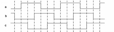
The assumed waveform using the above code could be visualized in the following diagram:
Once you have burned and confirmed the above code in your Arduino, it's time to move ahead and configure the remaining circuit stages.
For this you will need the following parts which hopefully you might have already procured:
Parts Needed
IC IR2112 - 3 nos (or any similar 3 phase driver IC)
BC547 transistors - 3 nos
capacitor 10uF/25V and 1uF/25V = 3 nos each
100uF/25V = 1no
1N4148 = 3nos (1N4148 is recommended over 1N4007)
Resistors, all 1/4 watt 5%
100 ohms = 6nos
1K = 6nos
Constructional Details
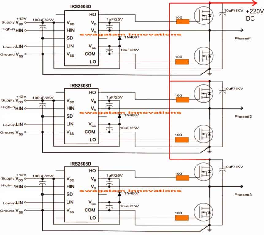
To begin with, we join the 3 ICs to form the intended 3 phase mosfet driver stage, as given below:
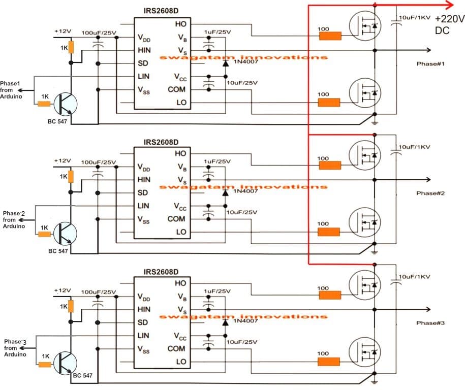
Once the driver board is assembled, the BC547 transistors are hooked up with the HIN and LIN inputs of the IC, and illustrated in the following figure:
Once the above designs are constructed, the intended result could be quickly verified by switching ON the system.
Remember, the Arduino needs sometime to boot, therefore it is recommended to switch ON the Arduino first and then switch ON the +12V supply to the driver circuit after a few seconds.
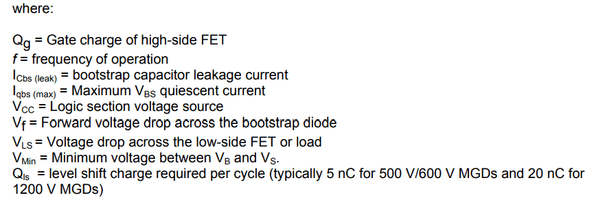
How to Calculate the Bootstrap Capacitors
As we can see in the above figures, a circuit requires a couple of external components near the mosfets in the form of diodes and capacitors. These parts play a crucial role in implementing precise switching of the high side mosfets, and the stages are called bootstrapping network.
Although already given in the diagram, the values of these capacitors could be specifically calculated using the following formula:
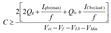
For getting quick results, you can use this Bootstrapping Calculator
How to Calculate the Bootstrap Diodes
The above equations can be used for calculating the capacitor value for the bootstrap network, for the associated diode we have to consider the following criteria:
The diodes activate or are enabled in the forward bias mode when the high side mosfets are turned on and the potential around them is almost equal to the BUS voltage across the full bridge mosfet voltage lines, therefore the bootstrap diode must be rated enough to be able to block the full applied voltage as specified in the specific diagrams.
This looks fairly easy to understand, however for calculating the current rating, we may have to do some math by multiplying the gate charge magnitude with the switching frequency.
For example if the mosfet IRF450 is used with a switching frequency of 100kHz, the current rating for the diode would be around 12mA. Since this value looks quite minimal and most diodes would have a much higher current rating than this normally, specific attention may not be essential.
Having said that, the over temperature leakage characteristic of the diode can be a crucial to be considered, especially in situations where the bootstrap capacitor may be supposed to store its charge for reasonably sustained amount of time. In such circumstance the diode will need to be a ultra fast recovery type to minimize the magnitude of charge from being forced back from the bootstrap capacitor towards the supply rails of the IC.
Some Safety Tips
As we all know that mosfets in 3 phase inverter circuits can be quite vulnerable to damage due to many risky parameters involved with such concepts, especially when inductive loads are used. I have already discussed this elaborately in one of my earlier articles, and it is strictly advised to refer to this article and implement the mosfets as per the given guidelines.
Using IC IRS2330
The following diagrams are designed to work as a 3 phase PWM controlled inverter from an Arduino.
The first diagram is wired using six NOT gates from the IC 4049. This stage is used for bifurcating the Arduino PWM pulses into complementary high/low logic pairs so that the a bridge 3 phase inverter driver IC IC IRS2330 can be made compatible with the fed PWMs.

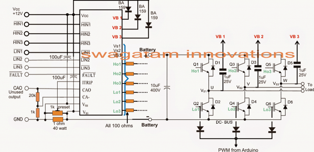
The second diagram from above forms the bridge driver stage for the proposed Arduino PWM, 3 phase inverter design, using the IC IRS2330 bridge driver chip.
The inputs of the IC indicated as HIN and LIN accept the dimensioned Arduino PWMs from the NOT gates and drives the output bridge network formed by 6 IGBTs which in turn drive the connected load across their three outputs.
The 1K preset is used for controlling the over current limit of the inverter by suitably adjusting it across the shut down pin of the I, the 1 ohm sensing resistor may be reduced appropriately if the current a relatively higher current is specified for the inverter.
Wrapping Up:
This concludes our discussion on how to build an Arduino based 3 phase inverter circuit. If you have any further doubts or questions on this subject please feel free to comment and get the replies quickly.
For the PCB Gerber Files and other related files you can refer to the following link:
https://drive.google.com/file/d/1oAVsjNTPz6bOFaPOwu3OZPBIfDx1S3e6/view?usp=sharing
The above details were contributed by "cybrax"


Questions & Answers
What do you think the delay(6.67) statement does in the code? It looks like it was copied from someone who doesn’t know what they are doing.
The Arduino delay() routine doesn’t do floating point:
https://www.arduino.cc/reference/en/language/functions/time/delay/
Hi, I cannot see any delay(6.67) statement in the code, can you please show me where exactly it is mentioned?
Although even my Arduino knowledge is not good, I would still like to investigate this.
Please let me know…
There are several floating point delays in loop():
void loop() {
int var=0;
digitalWrite(13, HIGH);
digitalWrite(8,LOW);
digitalWrite(12,LOW);
delay(6.67);
digitalWrite(12,HIGH);
while(var==0){
delay(3.33);
digitalWrite(13,LOW);
delay(3.33);
digitalWrite(8,HIGH);
delay(3.34);
digitalWrite(12,LOW);
delay(3.33);
digitalWrite(13,HIGH);
delay(3.33);
digitalWrite(8,LOW);
delay(3.34);
digitalWrite(12,HIGH);
}
The delay(6.67) will be truncated to delay(6) and the delay(3.34)s will be truncated to delay(3) and the code will run about 10% faster than planned.
Since I am not good with Arduino, I asked “Google Gemini” about this, and here’s what it said:
Yes, the statement is correct.
Here’s a breakdown of why:
Floating-point Delays: The delay() function in Arduino is designed to take an integer argument representing the delay time in milliseconds. When you pass a floating-point value like 6.67 or 3.34, the compiler will truncate it to the nearest integer, which in this case is 6 and 3, respectively.
Impact on Timing: This truncation will result in the delays being slightly shorter than intended. Since the delays are truncated by approximately 10% (from 6.67 to 6 and 3.34 to 3), the overall execution time of the loop will be about 10% faster than if the exact floating-point values were used.
To ensure accurate timing it’s recommended to use integer values for the delay() function or consider using alternative timing mechanisms that can handle floating-point values more precisely.
Are you saying that some AI thing says my statement was correct? It’s still silly to use floating point values because all of the alternative timing mechanisms are based on integers: integer milliseconds, integer microseconds, or integer clock cycles.
The easiest alternative timing mechanism is to use https://www.arduino.cc/reference/en/language/functions/time/delaymicroseconds/ (which has a limitation of 16383us, so it isn’t very flexible) To use it, you’d replace the delay(X) with delayMicroseconds(Y) with Y being the corresponding number of microseconds:
delay(6.67) -> delayMicroseconds(6667)
delay(3.33) -> delayMicroseconds(3333)
Then you are using integers which do not look foolish.
If you needed to adapt to lower speeds, with delays larger than 16383us, you might use something based on micros():
// delay for longer than delayMicroseconds()’s 16383us upper limit:
unsigned long startMicros = micros();
while(micros() – startMicros < 123000){
; // do nothing
}
…
Ok got it! Thanks for your feedback, I hope the readers will find the information helpful!
Hi,
+ Does the circuit have a feedback loop?
+ What about the frequency compensation?
Hi,
No the circuit does not include a feedback loop or compensation, it is just a basic 3 phase inverter circuit. However, since here an
Arduino is used to generate a constant frequency, compensation may not be required.
i have tried this code, why my delay just 9ms not 10 ms? please help for this :”
I am not good with Arduino coding so it can be difficult for me to help in this regard. The code was taken from the following forum:
http://forum.arduino.cc/index.php?topic=423907.0
I think you will need to adjust the delay values in the code appropriately to get the intended results.
it is just like delay(3.3) but execute delay(3)
Yes, you will have to adjust those delays to match your requirement.
Hello thanks for your job
Arduino needs sometime to boot <- Arduino is NOT for demanding applications. Its a toy platform for education, going to bite badly if you try demanding things. Its easy – at expense of everything else. It means slow, unreliable, bloated code, capable of using maybe 20% of what AtMega could really do. Microcontrollers on their own boot really fast to take control of their task. Its what they’re made for! Its Arduino, their boot loader and run time that screws it up. Once at this point, you know time has come, you no longer have newbie wishes, time to go write real firmwares, not arduino sketches. Getting rid of their boot loader and replacing it by fast booting firmware or own custom boot loader is a thing in such use case. Real virtue of engineer is to to solve difficult requirements of use cases, and when you make user sequencing power inputs, it means circuit needs more of engineering efforts on it. Additionally, circuits should be designed to survive “default state”. In case of MCU it means circuit should not blow up if MCU goes into reset or fails to boot for whatever reason, be it firmware failure and watchdog firing, or something. It means all critical pin states should be explicitly defined by external pull up or pull down resistors, to be in safe state before MCU takes control over. I dont see explicit pull ups/pull downs on FET driver inputs and that’s #1 improvement to circuit to suggest.
Hi, thank you for your great explanation!
Can you guide me on how to make a 3 phase half bridge inverter to drive a BLDC using discrete components? I would really like to implement an inverter without using the drivers IC’s, but I wonder how the circuit would change if I desire to control it with an arduino (and of course a different code).
Regards
A BLDC works using a feedback from the sensors, and I am not sure how a discrete half wave driver IC circuit can be used with a feedback system to control the BLDC motor. At the moment I do not seem to have any such circuit diagram or ideas regarding this subject.
Thank you for your quick response.
I think I formulated my question the wrong way.
I am currently building a FOC oriented controller and I already have the code for position and currents feedback. I also have a code to generate a SPWM signal from an arduino nano. However, my real question is how would the circuit change if I decide to replace the (IRS2330 IC) with discrete components (such as BJTs, capacitors and resistors) to control the 3 half bridge MOSFETs?Can I proceed with the practical circuit shown in H – bridge bootstrapping from the following link?
https://www.homemade-circuits.com/h-bridge-bootstrapping/
You can try that circuit, it was tested by other users to be OK, however I have myself not tested it practically…I got this circuit from one of the online forums.
hello i am finding 3- phase bridge to connect with arduino uno 3. the reason i will use 3-phase bridge to rotate bldc motor. i have a logic such like inverter process, for example code can process 3 hall sensor counting and 6 mosfet switching. but i can’t find i can any apply product. so please tell me what i buy any to use my code. thank you.
Hi, sorry, the above Arduino based 3 phase inverter cannot be used for driving a BLDC with feedback control.
thank you for your quick reply.
i have one question. i thought i can use logic like your upper arduino 3 phase signal generate code.
i think my logic is very same as your generate code.
so i wonder to ask you if i could use upper board.
thank you sir.
If you want to generate 3 phase square waveform then you can use the above code. You can use an Arduino UNO for this.
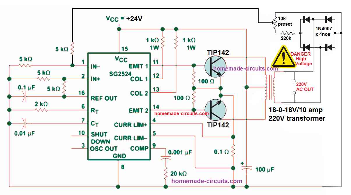
Please sir help me with simple puresine wave inverter circuit diagram
You can try the following design:
Connect a 3uF/400V capacitor at the output of the transformer to convert it into an almost pure sine wave inverter circuit.
क्या हम इस को 220वोल्ट से चला सकते है
You can connect a transformer with the mosfets to get 220V output.
Can this circuit be used for ac induction , if yes to minimize loses.
Please provide more details on what you mean by AC induction?
This is a good starting point for me. I will be using an Arduino to control a 3 phase IGBT rectifier. The problem is the voltage and frequency of the 3 phase AC input from a generator will be variable, not fixed from 600hz to 1200 hz depending on engine speed. Voltage is linear with frequency. What would you do to sample the output rectifier voltage, AC input frequency, then use that information to generate a square wave of a length that is a percentage of the AC waveform. This would trigger the IGBT for a percentage of the waveform that changes depending on the sampled voltage, say from 50% to 100% of the waveform. I can have a hall sensor pulse input to the Arduino to start the cycle
Thanks for your question, I appreciate it, however, sorry, I have no ideas…the concept looks quite difficult for me to solve.
Hi, thank for this information. Can one use IR2112 instead?
Yes you can use IR2112!
Hi
I am Vijay Singh Jakhar from Faridabad Haryana India
I am looking for ac induction motor controller
vijsinjak2@gmail.com
What’s app/phone call
+91-7056611119
Thanks with best wishes
Vijay
Hi,
You can perhaps try the first circuit from this article:
https://www.homemade-circuits.com/3-phase-induction-motor-speed/
Hello Swagatam,
very nice your article!
Could I also use it to control a three-phase motor with sine PWM?
Thank you Wolfgang,
Yes, 3 phase motor can be also controlled through a PWM across the low side MOSFETs
I want to make a linear speed control for Dc motor ,,but i have no idea on the components that i need for the project may i have your assistance
You can refer to the following post:
3 Simple DC Motor Speed Controller Circuits Explained
Hi Swagatam.
Thanks a lot for share your knowledge with us.
I have some questions, i hope you can help me to clary it.
1) in your last picture, you draw a diode connected to IGBT gate, the cathode of this diode is connected to Arduino (according to your note on this picture), why Arduino is connected on this point? IGBT Gate is handle by IRS2130 and the incoming PWM from Arduino must be connected to Hi and Li, so I can’t understand why you put this diode and the label too “to Arduino”.
2) IRS2330 needs just 3 pwn lines (one per phase), as each phase is connected to IC 4049 or to BC547 in order to generate the complement of each PWM line.
It means, microcontroller must generate just ONE PWM line per phase, it is ok?
3) we have 3 phases, but just thinking in one phase (in order to simplified the question and comments), if I need to generate un AC period with 500 PWM periods (250 for positive half period and 250 for negative half period), in ONE AC period, the Hi pin (IRS2330) will receive 500 PWM and 500 in Li too?
i am trying to full understand that as IRS2330 needs PWM and the complement of it, both pins will have PWM (no zero) on each PWM period…..it means, there is NOT any period where Hi has activity and Li is just zero, is it ok?
I was working on my microcontroller (STM32), generating 6 PWM lines : as example of one phase, the micro was generating for phase T1 ( as example:
Phase T1 (Hi_1), “+” AC half period: 0,10,30,50,90,90,50,30,10,0,0, 0, 0, 0, 0, 0, 0, 0, 0. 0
Phase T1 (Li_1) , “-” AC half period: 0, 0, 0, 0, 0, 0, 0, 0, 0,0,0,10,30,50,90,90,50,30,10,0
_____ + AC Half period ____ _____- AC half period _____
As you can see, I was not generating a complementary PWM, when Hi was active, Li was just zero….. and it is not ok,you use always Hi with PMW generated by microcontroler or Hardware and a complementary oh HI, Li.
as you can see, I was going in wrong direction, that is the reason of my questions, I need to understand how PWM must arrived at IRS2330.
I Hope can understand my questions.
best regards and thanks for your help
Alfredo (from Argentina)
Hi Alfredo,
Thanks for your questions.
In the last diagram, the 3 phase signals are connected to HIN, LIN pins of the IC. The gates of the IGBT through diodes are supposed to be connected to another Arduino PWM output either for RMS control, or for feeding SPWM to the low side IGBTs so that the output could be converted to sine wave.
I am sorry I did not explain this in the last diagram.
The HIN/LIN complementary pins must never be high or low together at any instant that is perhaps the only criterion for implementing the IC successfully.
Hi Swagatam .
thanks for your fast answer!!!!
everything is clear now.
Thanks alot for your help.
best regards
Alfredo
You are welcome Alfrdeo, Glad I could help!
Good evening Dear, please I would like to know the name of the software that can be used to draw the three-phase networks (delta and star). I use Pspice, but it does not allow a component to be rotated by 60 or 30 degrees for example. thank you.
Sorry dear, I have no idea about it!
hii
dear sir can you provide me pcb for this
sorry, PCB design is not available for this project!
The delay() function takes an unsigned long argument, so lines like this one are not doing what you expect:
delay(3.33);
Hi dear Sawgatam,
I have a project that I have 3 phase 380v 50hz and need power output 4x (48v, 3 phase, 16A, 200 hz).
As I know I need :
1: AC-DC Full Bridge to convert 3 phase 380v 50hz to a DC (V=Vrms*1.414=537v)
2: filtered DC output with 2 or more Capacitor
2: DC-DC converter to convert 537v DC to 48v DC or more.
3: Control the frequency with arduino or micro controller
4: DC-AC pwm
And I have 2 question:
– Which capacitors in farad and volt is ideal to use for filter the peak voltage?
– What is the best solution to convert DC-DC (I have 3kw 48v zener diode only)?
Thank you sir
Hi Yousef,
A filter capacitor should be ideally calculated using formulas. I have explained the procedure comprehensively in the following article:
Calculating Filter Capacitor for Smoothing Ripple
However calculating will give a very large value, so practically speaking, the approximate value could be anywhere between 100uF/1kv, 500uF/1kv
The best solution to convert DC to DC is through buck converter circuit