In this post I have explained how to make a 3 phase inverter circuit which can be used in conjunction with any ordinary single phase square wave inverter circuit. The circuit was requested by one of the interested readers of this blog.
UPDATE: Looking for an Arduino based design? You may find this one useful:
The 3 Phase Generator using IC 4035
The 3 phase inverter circuits explained in the subsequent sections of the article, will all basically need a good 3 phase generator circuit. One such good 3 phase generator circuit can be built using the IC 4035,. Let us understand how to do implement it with the following explanation:
This circuit creates 3 square wave outputs, each 120° out of phase, just like a 3-phase AC supply but in digital (square wave) form. It is good for testing 3-phase inverter circuits, BLDC motor drivers, or simulating 3-phase logic.
MAIN PARTS USED:
| Part | Function |
|---|---|
| IC 555 | Works like a clock – generates fast square pulses. |
| CD4035A | 4-bit shift register – shifts logic “1” and gives 3-phase signals. |
| MJE340 + Zener | Gives stable 12V to ICs even if input DC is high. |
| NOT gates (N1, N2) | Helps reset and invert signals properly. |
Full Circuit Diagram

HOW THIS THING WORKS, STEP-BY-STEP:
(1) Power Supply Side
- The top side of the circuit says “+12V to +100V DC” — this means input can be any voltage from 12V to 100V.
- That high voltage passes through a 10k, 1 watt resistor, then to the Zener diode (12V).
- The Zener clamps the voltage to exactly 12V, and the MJE340 transistor supplies regulated 12V to all ICs.
So no matter what voltage we feed (12V to 100V), the circuit ICs will only see 12V. Nice trick!
(2) 555 Timer Section
- The 555 is in astable mode means it keeps oscillating on its own, making square waves.
- The frequency is set by R1, R2, and C, this tells how fast the 3-phase signal rotates.
- Pin 3 of the 555 outputs these pulses, this goes into the clock pin of CD4035A.
- That pulse pushes the shift register forward each time, like "step forward" on each beat.
(3) CD4035 Shift Register Section
Now the magic happens here…
- CD4035 is a 4-bit shift register so each clock pulse pushes the logic “1” from Q1 → Q2 → Q3 → Q4 → repeat.
- But here only Q1, Q2, Q3 are used as outputs. These are taken as:
- Q1 = phase#1
- Q2 = phase#2 (inverted by N2 for better phase shift)
- Q3 = phase#3
Each of these are 120° apart from each other (as long as we consider each clock pulse = 120°).
- N1 is used for reset logic or pulse shaping (basic inverter from IC 4049).
- N2 inverts the second output so that the phase shift looks cleaner so Q1, !Q2, Q3 → gives better symmetry.
OUTPUT WAVEFORMS:
- All outputs are square waves.
- Frequency is same but each is delayed from the other by 120°.
- You get a digital-style 3-phase signal...
IMPORTANT POINTS:
- N1 and N2 are NOT gates, from IC 4049.
- You must pulse the SER input (pin 10) once at start (logic HIGH) or just connect it HIGH permanently.
- If nothing appears at output then check:
- 555 oscillation.
- Reset pin of CD4035 (must be LOW).
- Proper pull-ups on output lines.
The 3-Phase Full-Bridge Driver Stage
In the following 3 phase inverter diagram, remember the HIN, LIN pinouts must be fed with alternating pulses, which can be done using NOT gates from the IC 4049, or simply using a BJT BC547 stage.

In the above 3 phase generator circuit (second last diagram) using a sine wave doesn't make sense because the 4049 would ultimately convert it into square waves, and moreover the driver ICs in the last design employ digital ICs which will not respond to sine waves.
Therefore a better idea is to use a 3 phase square wave signal generator for feeding the last driver stage.
You may refer the article which explains how to make a 3 phase solar inverter circuit for understanding the 3 phase signal generator stage functioning and implementation details.
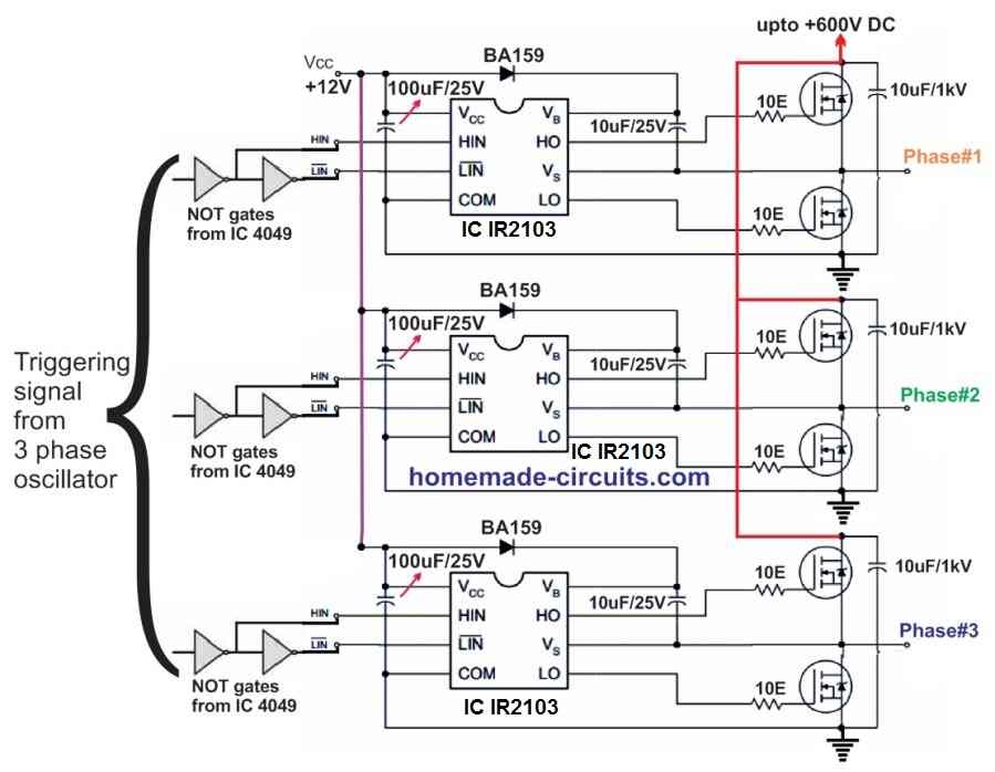
Using IC IR2103
A relatively simpler version of the above 3 phase inverter circuit can be studied below, using the IC IR2103 half bridge driver ICS. This version lacks the shut down feature, therefore if you do not wish to incorporate the shut down feature, you can try the following simpler design.
Simplifying the Above Designs
In the above explained 3-phase inverter circuit, the 3-phase generator stage looks unnecessarily complex, and therefore I decided to look for an alternative easier option for replacing this specific section.
After some searching I found the following interesting 3 phase generator circuit which looks pretty easy and and straightforward with its settings.
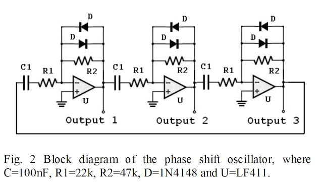
Therefore now you can simply replace the earlier explained IC 4047 and the opamp section entirely and integrate this design with HIN, LIN inputs f the 3 phase driver circuit.
But remember you will have to still use the N1----N6 gates between this new circuit and the full bridge driver circuit.
Making a Solar 3 Phase Inverter Circuit
So far we have learned how to make a basic 3 phase inverter circuit, now we'll see how a solar inverter with a 3 phase output can be built using very ordinary ICs and passive components.
The concept is basically the same, I have just changed the 3 phase generator stage for the application.
Inverter Basic Requirement
For acquiring a 3 phase AC output from any single phase or a DC source we would require three fundamental circuit stages:
- A 3 phase generator or processor circuit
- A 3 phase driver power stage circuit.
- A boost converter circuit
- Solar Panel (appropriately Rated)
To learn how to match a solar panel with battery and inverter, you can read the following tutorial:
Calculate solar Panels for Inverters
One good example may be studied in this article which explains a simple 3 phase inverter circuit
In the present design we too incorporate these three basic stages, let's first learn regarding the 3 phase generator processor circuit from the following discussion:
How it Works
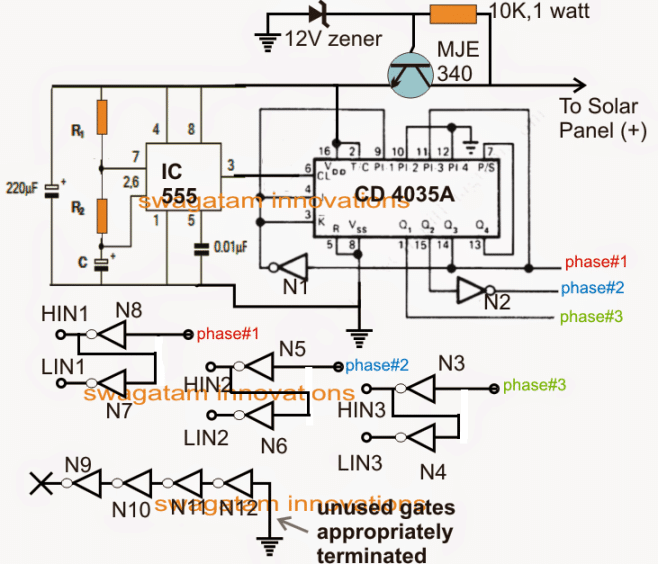
The diagram above shows the basic processor circuit which looks complex but actually it's not. The circuit is made up of three sections, the IC 555 which determines the 3 phase frequency (50 Hz or 60 Hz), the IC 4035 which splits the frequency into the required 3 phases separated by a phase angle of 120 degrees.
R1, R2 and C must be appropriately selected for acquiring a 50 Hz or 60 Hz frequency at 50% duty cycle.
8 numbers NOT gates from N3 to N8 can be seen incorporated simply for splitting the generated three phases into pairs of high and low logic outputs.
These NOT gates may be acquired from two 4049 ICs.
These pairs of high and low outputs across the shown NOT gates become essential for feeding our next 3 phase driver power stage.
The following explanation details the solar 3 phase power mosfet driver circuit
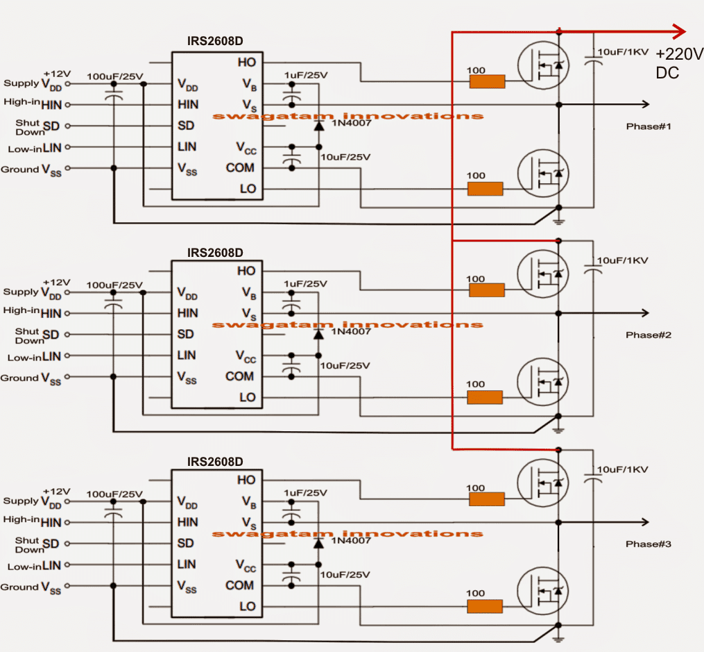
Note: The shut down pin must be connected to the ground line if not used, otherwise the circuit will not work
As may be seen in the above figure, this section is built across 3 separate half bridge driver ICs using IRS2608 which are specialized for driving high side and low side mosfet pairs.
The configuration looks quite straightforward, thanks to this highly sophisticated driver IC from International rectifier.
Each IC stage has its own HIN (high In) and LIN (low In) input pins and also their respective supply Vcc/ground pins.
All the Vcc are required to be joined together and connected with the 12V supply line of the first circuit (pin4/8 of IC555), so that all the circuit stages become accessible to the 12V supply derived from the solar panel.
Similarly all the ground pins and lines must be made into a common rail.
The HIN and LIN should be joined with the outputs generated from the NOT gates as specified in the second diagram.
The above arrangement takes care of the 3 phase processing and amplification, however since the 3 phase output should be at the mains level and a solar panel could be rated at a maximum of 60V, we must have an arrangement that would enable boosting this low 60 volts solar panel to the required 220V or 120V level.
Using IC 555 Based Flyback Buck/Boost Converter
This can be easily implemented through a simple 555 IC based boost converter circuit as may be studied below:
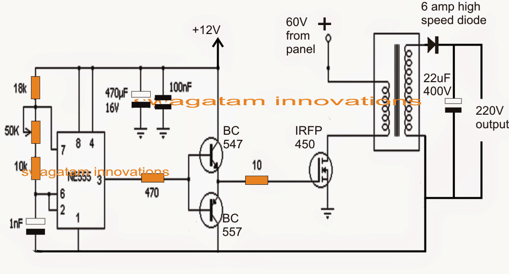
Again, the shown configuration of the 60V to 220V boost converter looks not so difficult, and can be constructed using very ordinary components.
The IC 555 is configured as an astable with a frequency of approximately 20 to 50 kHz. This frequency is fed to the gate of a switching mosfet via a push pull BJT stage.
The heart of the boost circuit is formed with the help of a compact ferrite core transformer which receives the driving frequency from the mosfet and converter the 60V input into the required 220V output.
This 220V DC is finally attached with the previously explained mosfet driver stage across the drains of the 3 phase mosfets for achieving the 220V 3 phase output.
The boost converter transformer can be built on any suitable EE core/bobbin assembly using 1mm 50 turns primary (two 0.5mm bifilar magnet wire in parallel), and secondary using o.5 mm magnet wire with 200 turns



Questions & Answers
Hi, Yes some of your points are correct, I'll reassess the above designs and look for appropriate solutions and update them soon..
Done….I have updated the corrected versions, all the issues have been addressed correctly (hopefully).
Hi, maybe the High Frequency PWM signal from the 555 can be applied (through the diodes) to the outputs of the Hex Buffers, so it can quickly turn on/off the square wave signals.
No, that would cause oppostie responses for the NOT gate inputs….it would be more correct to connect the diodes with the shut down pins of the half bridge driver ICs, in fact diodes won't be required, pin#3 of the 555 astable could be directly integrated with the shut down pins of the driver ICs.
Hi i think this circuit will be good for me i would like use for 3 phase 400 volt asynchronus motor as generator for make induction in motor to generating electricity , my aim is from 12 DCvolt engine alternator who spin asynchronous motor convert to 12 v ac and with transformer make 400 v AC an this 400 ac to VDC I dont want use capacitors use between faces for that i would like electronic circuit i am little confuse thats pins SD where i should connect it ?
Hi, the above circuit is a 3 phase motor driver circuit from a single phase source…..so i cannot figure out how it would help your application.
SD should connected to positive for normal operation, if it's connected to ground the whole IC freezes.
it helps thanks
Sir im a electronic hobbiest i want a pwm inverter circuit with charger mains changeovr and low battery shutdown. THANK YOU. If u can send it to my e.mail vikramsha555@gmail.com
Vikram, if possible i'll to do it soon and post it to you.
I HAVE PROBLEM WITH A3(LM324)..
No Voltage on Gate 3….Output 0 Voltage with No Frequency…
On Gate 2- Voltage 6.56 with 50Hz
On Gate 4- Voltage -6.70 with 50Hz…
How can I solve This…..Advance Thnx
check input pin voltages of A3, if the voltage vary at the inputs then the output should also vary accordingly.
https://docs.google.com/file/d/0BzY3XDOhN0DWREswREtVQVJQalE/edit?usp=docslist_api
Watch This And Give me Answer For This Question
link is not opening, make the share option to "public"
did you make the circuit exactly as it's shown?
With the value of a few component i'm lost:
1). R1, P1 from the square wave generator?
2). rectifier bridge used for the supply of the motor
3). the driver transistors
Thanks
1) R1 and P1 will need to be determined by experimenting as per the desired output frequency.
2) rectifier diode current will depend on the amp specs of the motor.
3) you can use IRF840 for the mosfets.
Hello sir I want to design an 3ph inverter circuit using mosfet, so can you tell me what are the components specification for building this circuit .
Regards.
hello Arindam, you can go through the above published article for the details.
Can i use this circuit from 12 volt battery
yes will do…
hi sir,
i am going to do project under power electronics.i have to design 3-phase inverter.do i have to use IGBT driver for the circuit to work.
Hi senthil, yes using IGBTs will give better results and is recommended for a 3 phase inverter project
Can this circuits be modified to control a brushless 12 v motor
yes it can be, you can refer to the following article for more info:
https://www.homemade-circuits.com/2014/12/simple-3-phase-brushless-bldc-motor.html
Hi sir… I want to convert single phase 240v to 3 phase to drive half HP AC induction motor.. On which point i have to make changes
Hi Sagar, for your application you just have to use the last and the second last circuits, however the output will not be a sine wave, rather a square wave.
Pls what is the IC name of the Driver Circuit???
And value of R1 and P1
Hi sir, pls help me with the name of the IC in the driver circuit.
Hi Ambrose,
It's IR2103
Thank you very much sir.
you are welcome!!
Hello sir, do I need to connect more IGBTs or MOSFET in paralel to have more wattage To drive 6kw rated Motor??
yes, more devices in parallel would yield more equivalent power
Hello sir I've foud your post ver6 useful to me but a little confused you'd used 555 timer with first 4047 but in after corection you didn't add 555 timer…..why……thank again for such useful post
Thank you Muhammad, the 555 IC stage is for inserting PWM into the inverter in order to make the waveforms modified sine waves,
I did not include it in the revised diagram just to keep it simple, you can add it if you want across the HIN, LIN inputs of the driver IC.
Dear Sir,
Can only LM555 be used for PWM instead of 4047 at all. is the output of 4047 in sine form or square waves.
Dear Debu, yes IC 555 can be used instead of the shown 4047…good suggestion thanks!
4047 has a square wave output
Sir ow we convert 555 square output to Sine Wave
Muhammad, you can do it by inducing high frequency PWMs on the gates of the mosfets, please refer to the following article for more info:
https://www.homemade-circuits.com/2013/04/how-to-modify-square-wave-inverter-into.html
I am working on 3 phase inverter I have simulated above circuit in proteus.
i gave sine wave as input to lm 324 accordingly i get 3 phase voltage but when this output i given to ic4049 i didnt get any output.
try the 3 phase generator stage that's discussed in the following article:
https://www.homemade-circuits.com/2015/04/solar-3-phase-inverter-circuit.html
the first diagram
Hello sir,
in order to perform the three phase to 2 phase conversion by d-q transformation. then how it will be implemented in hardware. please do the needful. Can you provide me your email id??
Hello Neeta, I can't produce the calculation for the proposed circuit, since the design is a square wave inverter and the stages are all digital I don't think the dqo transformation would be relevant, even if it is so I have no idea how to do it for the presented design.
my email can be found in the contact page, at the top
Please sir
Where do I connect shutdown pin to??
shut down pin can be left unconnected, it must be used only if an automatic output correction is required or for any similar protection switching.
sir, i didn't get your email address.
it's given in the "contact" page.
OK you can see it below:
admin@162.240.8.81
Sir, If I need 3 phase inverter with 100Hz to the motor, how much the frequency input of my inverter?, I can imagine only if push pull inverter the input is 2X then output, isn't it?, thanks in advanced.
Ronald, which circuit are referring to? if it's the 4047 circuit above, then it should be 100Hz for your application.