A Taser circuit also known as Stun Gun circuit is one non-lethal electric shock producing unit used to paralyze a person for a time being without causing any severe damage or injury. It is a very useful device, especially to immobilize an attacker.
Using and making of stun gun is restricted in most of the countries.
However, in the United States of America, some states allow the use of stun guns.
A stun gun is available in variety of styles like lipstick stun guns, cellphone stun guns, stun batons, police force stun guns, pink ribbon stun guns and disguised stun guns.
Warning: The circuits I have explained below are designed to generate high voltages in the range of many kilo-volts, which may be capable of delivering a painful shock. Appropriate caution is recommended while building these projects.
How it works?
Please read the following instruction before constructing:
Also known as a Taser gun this gadget generates substantial voltage pulses which can disrupt muscle tissues and neurological system, forcing any individual who touches it in a condition of mental bewilderment.
The unit may be used against attacking beasts or dangerous intruders.
Be aware that, this gadget could be prohibited in your country.
This gadget may be extremely dangerous on folks having cardiac issues, who may be using external electronic apparatus (like peacemakers), since it can deliver quite a bit of RF interference.
Don't attempt reckless behavior using this gadget, it is far from a plaything.
A Taser functions like two-stage voltage converter. In the first stage, the high frequency switching transformer increases the battery voltage to several kV to charge the capacitor. After the capacitor is charged, it powers the second transformer by increasing the voltage to 10 – 50kV (approx.) with the repetition rate of 5-40 Hz (approx.).
Taser Types
There are basic types of Taser: Multiplier, Thyristor and spark gap. Multiplier Taser is made of one transformer having voltage of higher output and it runs on DC voltage.
This type of Taser also has high-voltage capacitors and diodes and it is for the capacitors that multiplier Taser makes loud sound.
The Thyristor type is the most efficient one. Here the voltage of the capacitor is not high (250 – 500 V approx.) and it functions with the aid two main components: resistive divider (neon lamp) and diac.
The spark gap guns on the other hand is the most cheapest and ineffective stun gun. As the name implies, it has spark gap to function and the voltage of the battery is charged with transistor converter.
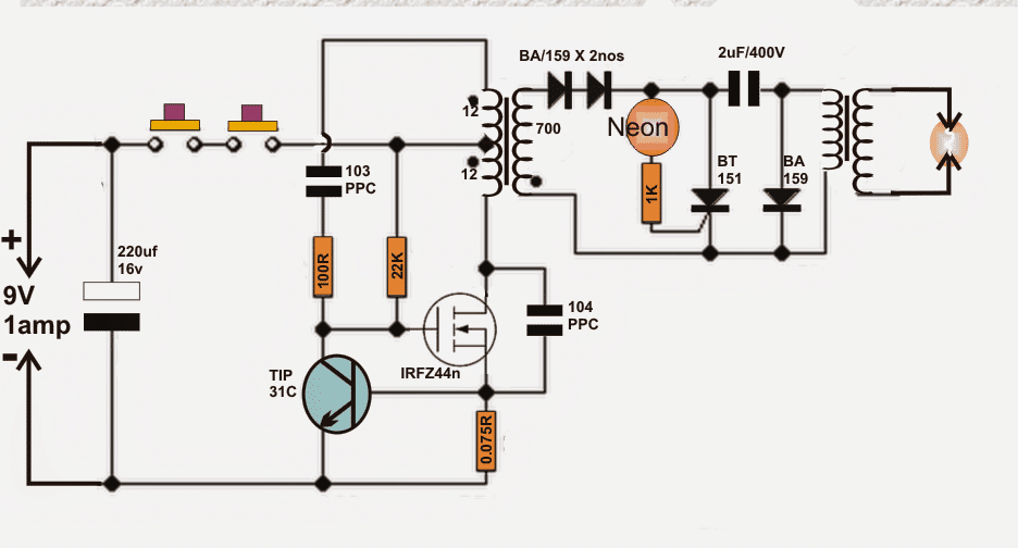
Design#1: How I made my Taser
Of the three types of Tasers, I chose to go ahead with the Thyristor because of its effectiveness. I used MOSFET (Metal–Oxide–Semiconductor Field-Effect Transistor) to build the voltage converter. The main reason to use MOSFET is purely from the point of efficiency.
In a push-pull converter which is generally used in stun guns, the level reaches around 20% whereas in MOSFET the converter gives efficiency as much as 75% with the working frequency of 80-120 kHz.
I then used a gate thyristor for the second switch along with four neon glow lamps with the ignition voltage of 95V and the pulse repetition rate of 30 – 50 Hz.
Transformer Specifications
For inverter transformer, I preferred to use EE core based transformer keeping the middle column cross-section of 20 – 25 mm2.
The air gap of 0.5mm thickness is place in the mid column. The primary polarity is set to 2x12 turns of the diameter of the wire (0.4mm) while the secondary polarity is set to 700 turns of wire (0.1mm).
The secondary polarity is wounded in multiple isolated layers. The reason to isolate the layers is to avoid breaking the wire enamel under high voltage. There are two electrodes in a Taser gun. They look like a dart and are connected to the main unit with a conductive wire.
Battery Specifications
One can power a stun gun with either six 1.5 V cells or seven 1.2 V cells.
The best option is to have two cells or Li-pol or Li-ion connecting the series. It should be noted that this stun gun may draw current upto 1.5 amps when switched ON, which means ordinary batteries might not work efficiently, and drain out quickly.
Written and Submitted By: Dhrubajyoti Biswas
Circuit Diagram
Design#2: Using IC 555
The proposed stun gun circuit description may be understood as follows:
The 555 IC is connected as a astable to generate rectangular waves with variable frequency and duty cycle (see the potentiometers and diode).
This signal is fed to a IRF840 Mosfet (not necessary to incorporate totem transistor network, as frequency would be reduced, nonetheless the IC has adequate current potential to swiftly charge/discharge the gate).
As an alternative for the mosfet a bipolar transistor works extremely well (add a 100 ohm resistor between 555 and base of the transistor).
Proper BJT could be BU406, but additionally scaled-down BJT may be ok, take into account that it should be able to cope with a minimum of 2A nonstop.
The inductive boost snubber isn't called for since the electrical power is lower which is practically completely adsorbed to charge the tank capacitor, furthermore because this gadget is battery powered we don't wish to disperse the power on a resistor, yet we need to produce the sparks.
With a snubbing system you are going to encounter decreased firing levels. Utilize A PUSHBUTTON SWITCH FOR Protection
Building the Transformer for the stun gun circuit:
This could be the actual tedious aspect. Because it in retailers we have to construct these. Components essential: enamel copper wire (0.20 mm or 0.125 mm), ferrite rod, LDPE sheets (0.25 mm).
Coat the ferrite rod with a application of ldpe (polyethylene, as a substitute utilize electric insulating tape) and stick it (or tape it) Position 200-250 winding on the ldpe (a lot more winding would do in case the rod is more than 1'), an additional ldpe application, yet another 200-250 winding and so forth to eventually have 5-6 tiers (approx 1000-1400 turns nonetheless supplementary turns wouldn't negatively affect the functionality), then again be cautious for internal arcing that could destroy it.
Insulate it once more and set the primary winding, 15-20 turns of 1mm wire would be simply fine, an excessive amount of winding will probably lead to lesser current and reduced spike in T2 secondary on account of decreased rise period, and too few is not going to saturate the core.
Go for MKP capacitors since they have minimal ESR and ESL (these are popular in tesla coils as mmc capacitors).
The Spark Gap
The spark opening could be straightforwardly a pair of crossed (although not touching) 1 mm spaced wires. It works like a voltage regulated switch, firing when the voltage is just nice to ionize the air between them (transforming it to plasma with smaller resistance).
Remember that it could be sensible do put it into a compact plastic box and stuff with oil allowing bubbles away don't employ motor oil or frying oil, rather organic mineral oil which includes zero water inside.
Circuit Diagram
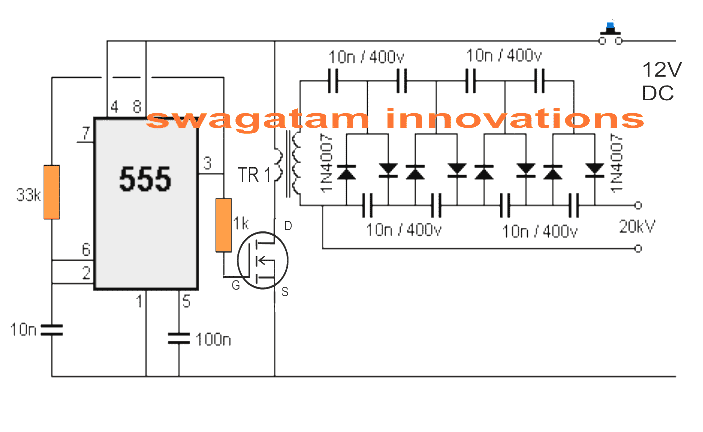
Parts List
- Resistors 1/4 watt 5% CFR
- 33k - 1no
- 1k - 1no
- Capacitors
- 0.01uF ceramic - 1no
- 0.1uF ceramic - 1no
- 0.01uF/400V metallized polyester - 8nos
- diodes 1N4007 - 8nos
- Mosfet - any N-channel general purpose mosfet with minimum 1 amp current (ID)
- IC - IC 555
- Transformer - as explained in the article


Questions & Answers
Nice article well written and concise. I like the various options you explore. Plus its always nice to see a circuit using a 555 IC. A grandfatherish ic that still serves a relevant function. Amazing for a 50+ year old IC. I am a retired baby boomer hobbyist. If there are any other circuits or sites you can point out for me it would be appreciated.
Thank you Thomas, glad you liked the article.
Yes indeed, the 555 is an amazing multipurpose device, there’s not been a single device so far which could replace this versatile IC.
If you are looking for small DIY type circuits, I would recommend you the following post, hope you like it:
https://www.homemade-circuits.com/circuit-projects-for-beginners-and-school-students/
Hello again Mr Swagatan,
Thanks you for your answer.
MOSFET Taser gun
The problem I can’t get the ferrite coil to build the Transformer.
Do you know its impedance value?
From an other supplier I can get circle ones with out air gap 0.5 mm like the ones on the above schematic.
I can get for exemple a circle ferrite coil NI-ZN iron Magnetic ∅7mm measured from inner and ∅13mm measured from out and width 5mm.
I can get other different circle ones as well, but I don’t know wich ones are the best and also its impedance value.
If you can help I will be very greatfully
Regards
José
Hello Jose,
The ferrite core should be E-core type, just like the ones which are used in mosquito swatter bats.
Sorry, I do not know about the exact size or the impedance value.
Hello Mr Swagatan
On the MOSFET taser gun show a Neon lamp of 95V, but don’t mentioned the amperage.
Do you know the amperage?
I looked at the my supplier page and dort mentioned 3 sorts of Neon lamps:
90V 65ac 300mA
90Vdc 65Vac 0.3mA
230Vac 1.4mA
It’s one of those suitable to replace the
95V mentioned on the diagram?
And do you know what sort of isolating lyer material to aplay on the Transformer with700 wiring turns ?
Thanks
José
Hi Jose,
I have no proper information about this since the article was written by another author. I guess a 300 mA should be fine.
You can use any PVC insulation tape for the isolation.
Great Mr Swagatan!
Hi Jose, there’s one more thing I want to add. If we are not using the right side transformer then there’s also no need of using the SCR and the neon lamp etc,
Hello Mr Swagatan,
For this MOSFET taser gun my supplier said he doesn’t have any Transformer Core to set the wiring turns.
Do you don’t have any other idea how i can maybe make it my self my self ?
Thanks
José
Hello Jose,
A transformer is a must in this type of circuits, the high voltage cannot be generated without a transformer.
If you are having difficulty in building a ferrite core based transformer, you can try any ordinary step down transformer, as explained in the following article
https://www.homemade-circuits.com/simple-high-voltage-generator-circuit/
Hello Mr Swagatan.
I’d like to have, please an explanation.
On the MOSFET Tesar Gun , it’s explain about 4 Neo Glow lamps with voltage of 95V, but on the diagrama just show one
lamp with 1K resistor. Have to be 4 lamps in wich one with 1K resistors, maybe on series?
And on the Transformer explanation just
explain about 1 Transformer of 2x 12 turns of 0.4 mm Wire and 700 turns of 0.1 mm Wire.
But on the diagram shows 2 transform
ers and one of them is connected to the 2 electrods, but not show any sort of coil and how many turns and thickness of de wire is the secound one.
Thanks you
José
Hello Jose,
Sorry for all the confusions. Actually this article was written by some other author, it is not designed by me.
According 4 neon lamps are not required for the gate triggering of the SCR. Just one neon lamp with a 1K series resistor should be fine.
For the transformer, only one main transformer with 2×12 and 700 turns should be enough. The second transformer at the extreme right side is not required.
Thanks you, Mr Swagatan
You are welcome Jose!!
Hello Mr Swagatan
On the thyristor Tesa gun,
I’ve difficulty to understand the componnent PPC 103 and PPC104.capacitores.
I think PPC stands for Particle Projection Cannon. And 103 and 104 is the value of the capacitor 10nF and 100nF isn’t?
They are normal 10nF and 100nF capacitores or they are special capacitores?
Tours sincerelly
José Afonso
Hello Jose,
I cannot find any thyristor based taser gun in the above article. I guess you are referring to the first MOSFET based taser gun circuit
PPC stands for PolyPropelene Capacitor, as shown below.
Yes 103 = 10nF and 104 = 100nF
simple and to the point. what a relief
Is it possible to create a spark gun that shoots out an electric spark a short distance that can kill or stun insects?
That does not look possible since that would require millions of volts to be generated.
So many HV supplies to look at, but none ever mention how many mili amps output, I am working an XRF unit and need up to 60 KVA at 5 Ma for my Xray tube any suggestions of components for diodes and caps.
needed . Thank You Leo in Alamogordo NM
Hi , did you found suitable output current and voltage as you mentioned? I need such circuit too
Sorry, I am not sure about how much mA this units will produce. For 60 kV you may have to add more number of turns on the transformer secondary, or add more number of diode capacitor in the ladder network, or do both.
Also wanted to add, the best frequency to induce localized muscle lock (and pain) is 19 Hz. If your design is any multiple of that, it should work, but that frequency has really the best result. It’s not just the power of the electricity; it’s simulating the nervous system’s own operation in order to hijack it.
Note: it’s the frequency Taser was forced to reveal in court when they were sued in New York. It’s not considered vital to their operation. But it is in fact important as a consideration for effectiveness of the designs.
So, some people might want to remember that when calculating their 555 discharge oscillation. Also, I’d recommend a secondary step-up to 50kV, because the 20kV has to compensate with higher amperage, which could actually turn lethal if it hits the wrong spot. On the other hand, the higher voltage has the added benefit of inducing more pain in an attacker, giving you a far better chance of getting away.
Noted. I hope the readers will find the suggestions useful!
Hello,
I am looking for someone to help me understand this circuit.
I would like to know which elements affect the change in the current value at the output, which for the operating frequency,
It was explained in the description what affects the voltage at the output, but I do not know how the voltage change at the input will affect. How the change of MOFSET to another one will affect the operation of the system. What MOFSET parameters are important in its selection.
please help.
The output voltage depends basically on the transformer winding ratio, and the capacitor diode stages.
MOSFET power is determined by its VDS and ID rating which are basically the drain to source voltage capacity and the current handling capacity at 25 degrees Celsius. If the above two ratings are higher than the output instantaneous sparking wattage, then the MOSFET can be considered OK and compatible.
Thank you very much for your comprehensive answer. I have one more question. Can you help me calculate the end discharge energy according to the components used.
Would you help me to prepare an excel sheet calculating circuit parameters depending on the change of individual parts? As long as it is at all possible.
Best regards.
Sorry, providing calculations can be difficult for me due to lack of time!
What is the specification of the second transformer in fig 1??
Will turning on the transister somehow cause the MOSFET to turn off? Is that how it forces the power going into the primary windings to change direction? Please help this is my first project since high school electronics.
The BJT is only for controlling current, it is not involved with the generation of the oscillations or the frequency. If the current tends to rise, an equivalent amount of voltage will develop across the 0.56 ohm resistor which will force the BJT to conduct and ground the mosfet gate, inhibiting its conducion…
Thanks. The “0.56 ohm resistor” in my curcuit is 4 watt 0.07 ohm which according to multimeter, has less resistance than the wire connected to the transister base. Correct me if I’m mistaken, In my case no voltage develops across the resistor, and the transistor never turns on. Would that cause problems such as MOSFET getting hot?
A 0.07 ohms would require 8 to 9 amps to activate the shown BJT, which may be too high. If your mosfet current is rated above the power supply current in that case this BJT and the resistor stage can be entirely eliminated. The mosfet could be mounted on a heatsink for avoiding over heating
If the BJT is removed, what’s controlling the MOSFET? I’m assuming the MOSFET is supposed to switch on/off many times a second.
the coil, the resistors and the capacitors together with the mosfet are responsible for creating the oscillations.
I’m trying to build the inverter transformer. Found a set of ferrite E cores with a 1mm air gap in the middle column. Cross sectional area is 25mm2. Should it work OK for the inverter transformer? And how many isolation layers do I need in the secondary windings? Can 38 AWG polyurethane insulated magnet wire withstand 500 volts?
Ferrite cored transformers are complex devices and cannot be estimated without calculations, you can try referring to the following articles and see if they help you to optimize as per the specs.
https://makingcircuits.com/blog/how-to-calculate-ferrite-transformer-for-smps/
https://www.homemade-circuits.com/how-to-design-a-flyback-converter-comprehensive-tutorial/
Hi there,
You stated “It should be noted that the stun gun draws current of around 1.5 V” when current is measured in amps not in volts.
Thank you for notifying, I have corrected the description.
Can I replace a BA159 diode with a BA157 diode
BA157 is rated at 400V therefore it won’t work
Does both the transformers in fig 1,require the same specifications you’ve mentioned?
No they are different, the upper one is center tap, while the lower one is two wire on the primary side.
can you give the specifications for that transformer 2 in design 1.& thank you for the response in advance
The shown 12+12 turns and 700 turns can be wound on any small ferrite transformer, but to get an optimized output you may have to experiment with the value of the 103 PPC capacitor until the highest amplitude is obtained at the output of the same transformer.
Don’t you sell this as a components Kit? theres a million different schematics out there, most are either dangerous or don’t work, and when I finally find a decent schematic, either the components aren’t labelled properly, or they are really hard to find in component stores. I understand the science behind the circuit, and the risks of making it, I just want a reliable source of components for this project, in the form of a Kit. The internet can be hard work sometimes
sorry, I don’t sell components because selling and maintaining an online store can be a lot of work. But you can get the parts from any reputed online store.
all the resistors are 1/4 watt 1% MFR
220uF capacitor is electrolytic, remaining are metallized PPC
sir how to make cartridge of taser gun,because i am doing it as a project work please help e out to get that sir or mail me at darshanmd.dr@gmail.com
darshan, you can easily find the details with an online search….