A very simple automatic solar light system for illuminating your garden passages can be built using some LEDs, a rechargeable battery and a small solar panel. The system automatically switches ON the lamps at dusk and switches them OFF at dawn.
Main features
Although the following simple automatic solar LED garden light circuit looks simple, it includes a few interesting features which makes this design extremely adaptable, versatile, safe, efficient and long lasting.
The mains features are listed below:
- Automatic charging of battery during daytime with LEDs turned off, and automatic switching ON of the LEDs during nighttime.
- Proper current limiting for the battery to safeguard the battery from excessive charging.
- Current limiting for the LEDs which can be adjusted as per the required number of LEDs.
- Battery over-discharge protection ensures that the battery can never be overly discharged by the LEDs, which in turn ensures a longer life for the battery
How it Works
As can be seen in the following circuit diagram, the design basically consists of a solar panel, a couple of NPN transistors, LEDs, a battery, a few resistors and diodes.
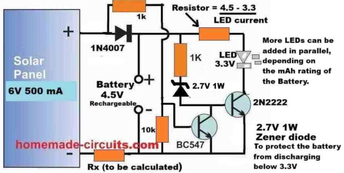
Referring to the circuit diagram above, the working of each of the components can be understood with the following points:
The solar panel supplies the peak voltage of 6 V, at 500 ma during daytime, which charges the battery as long as this voltage is available from the solar panel.
The resistor Rx keeps the charging current to a safe lower level so that even after the battery is fully charged, the minimal current does not harm the battery.
The value of the charging current determining resistor can be calculated using the following formula:
Rx = (Vsolar(peak) - Vbattery(full)) / Icharge
Rx = (Solar peak voltage - Battery full charge voltage) / Battery charging current
Example:
Solar Panel Voltage = 6V
Battery Full Charge Spec = 4.2V
Battery Charging Current (optimal) = 500 mA
Rx = (Vsolar(peak) - Vbattery(full)) / Icharge
= (6 - 4.2) / 0.5
= 3.6 Ω
Rx Power = (Vsolar(peak) - Vbattery(full)) * Icharge
= (6 - 4.2) * 0.5
= 0.9 watts or simply a 1 Watt
However, if you want better protection than just a current limiting resistor, you can opt for a regulated charging system, as discussed in the next design after this explanation.
The BC547 transistor ensures that the LED driver transistor using 2N2222 remains turned off, as long as a base voltage of at least 0.6 volts is available from the solar panel.
Meaning, until the voltage from the solar panel has not dropped below 0.6 V, the BC547 transistor remains switched ON, causing the base of the 2N2222 to remain grounded, and turned off.
Therefore, until it is significantly dark or until the solar panel is able to supply at least 0.6 V to the BC547 base, the 2N2222 remains switched off, which in turn causes the LEDs to remain shut off.
Once the solar panel voltage drops below 0.6 V, the BC547 transistor slowly starts turning off, causing the 2N2222 to slowly start turning ON.
As the 2N2222 slowly turns ON, its collector LEDs also begin slowly getting illuminated, using the stored power from the battery which was charged during the daytime using solar energy.
Once it is completely dark and the BC547 is fully turned off, the 2N2222 BJT conducts fully causing a full illumination on the LEDs.
The LEDs now illuminate fully using the stored energy from the battery, and the battery slowly starts depleting its power through the LEDs.
The battery keeps the LEDs illuminated until the battery voltage has drained down to its lowest discharge level, which happens to be around 3 V for the 4.5 V battery shown in the diagram.
However, as we know that a BJT can conduct only until its base voltage is around 0.6 V higher than its emitter voltage.
But since the base of the 2N2222 is clamped with a 2.7 V zener diode, it means that the base voltage of the 2N2222 needs a minimum of 2.7 + 0.6 = 3.3 V to enable its proper conduction.
So, when the battery voltage drops to around 3 V, the base of the 2N2222 does not satisfy the minimum required base voltage of 3.3 V and thus it turns OFF.
In this situation the LEDs also shut off, preventing any further discharge of the battery, which protects the battery from over discharging.
A series resistor with the LED positive line ensures that the LEDs are protected from over current and are always safely illuminated without any possible harm or damage.
The limiting resistor can be calculated using the following formula:
R = (VBattery - VLED) / ILED
R = (Battery Voltage - LED forward voltage) / Total LED safe Current.
Example:
Battery Voltage = 4.2V
LED Voltage = 3.3 V
LED Current = 20 mA
Then,
R = (VBattery - VLED) / ILED
= (4.2 - 3.3) / 0.02
= 45 Ω
R (Power) = (4.2 - 3.3) * 0.02 = 0.018 watts or simply a 1/4 watt should work...
The next morning when sunlight falls on the solar panel, the BC547 yet again disables any conduction of the 2N2222 BJT and the LEDs, initiating a fresh charging cycle for the battery.
The above cycle now keeps repeating each day and night providing the required automatic illumination of the garden premise using this simple, versatile garden LED light circuit.
You may also like this PIR Controlled Solar Garden Light Circuit
Solar Garden Light with Regulated Battery Charging
The following diagram shows how the above simple design can be upgraded into an automatic solar garden light circuit with regulated battery charging.
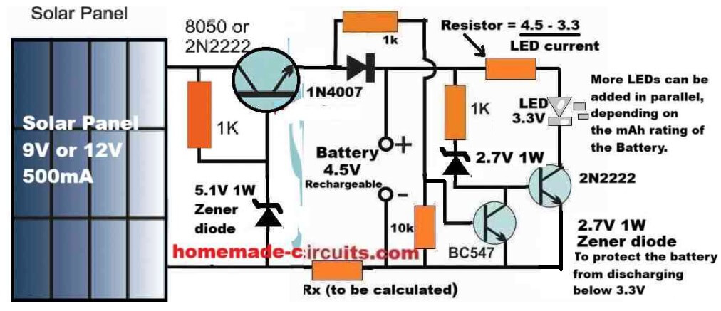
The automatic operation of the LED lamp stage is actually exactly identical to our previous design, the only difference being the inclusion of the voltage regulator stage incorporating another 2N2222 BJT in an emitter follower configuration.
As we know that in an BJT emitter follower configuration, the emitter voltage of the BJT follows the base voltage, meaning the emitter terminal of the BJT replicates its base voltage.
However, due to the BJT's internal base/emitter voltage drop of 0.6 V, the emitter voltage is always around 0.6 Volts lower than the base voltage.
In the above regulated solar garden light circuit diagram, since the base of the left side 2N2222 emitter follower regulator BJT is clamped with a 5.1 V zener diode, means that its base voltage is fixed at 5.1 V, regardless of the solar panel voltage.
Therefore, the emitter voltage of this regulator 2N2222 BJT will be always fixed at around 5.1 - 0.6 = 4.5 V.
This 4.5 V fixed output is what we require for a safe charging of our 4.5 V battery, which means the 4.5V battery can be never charged above its full charge level of 4.5V, ensuring a safe regulated charging for the battery.
Parts List
- Resistor, 1k, 1/4 W CFR = 3
- Resistor, 10k 1/4 W CFR = 1
- LED limiting resistor and Battery limiting resistors as discussed previously.
- BJT 2N2222 = 2
- BJT BC547 = 1
- Rectifier Diode 1N4007 = 1
- Zener Diode 5.1 V 1/2 watt = 1
- Zener diode 2.7 V 1/2 watt = 1
- LEDs as per requirement and battery capacity.
- Solar Panel = 9V to 12V, 500 mA
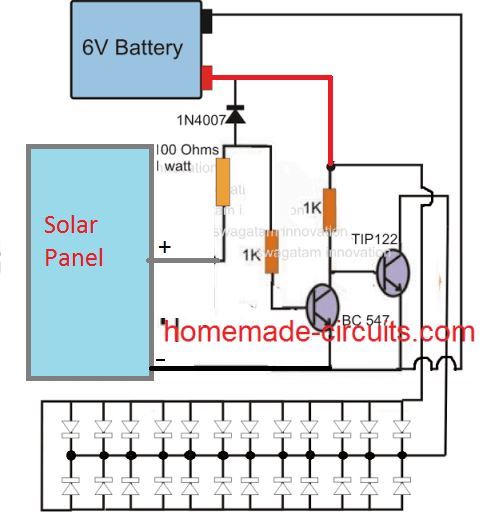
Using NPN Transistors
The above explained designs can be also replicated using two NPN transistors as shown in the following diagram:
Solar Pathway Light Circuit with Constant Voltage
If a Li-Ion battery is intended to be used for the above explained circuit, a constant voltage feature becomes crucial for safeguarding battery life and prolonging it.
The following circuit show how this may be done by adding a simple voltage follower regulator circuit:
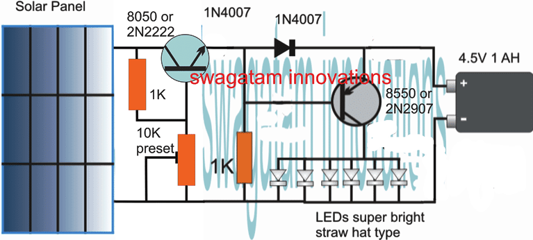
If a 3.7V Li-Ion battery is used, make sure to adjust the 10K preset to achieve precisely 4V across the output points where the battery is supposed to be connected, do this adjustment without connecting the battery.
The 4V level ensures that the battery is never overcharged (at 4.2V) and this also allows the circuit charge the battery without a constant current supply.
1.5V Solar Garden Light with Enhanced Features
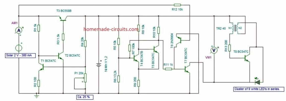
The following solar powered garden light was designed by Mr. Guido which includes additional features such over charge and low charge cut off for the battery and with a Schmidt trigger.
This ensures that the connected battery is never allowed to charge or discharge beyond unsafe levels.
The main attraction of the circuit is the use of a single rechargeable AAA penlight cell, which is able to light up a 3.3V high bright LED through an attached Joule thief circuit.
High Power 12V Garden Light Circuit
The following image shows a high power automatic garden porch light circuit using a 12V 7 Ah battery. The LEDs used are high power 1 watt LED each. Since 9 LEDs are used the total power output becomes 9 watt.
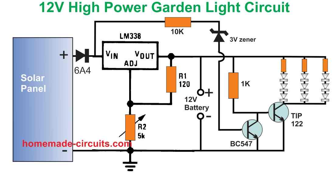
The circuit is designed to automatically switch ON the LEDs when the darkness level drops sufficiently and the solar panel voltage drops below 3 V.
The LED series resistor values can be calculated using the following formula:
R = Battery Supply - LED FWD V Drop / LED Current
= 13 - (3.3 x 3) / 0.3
= 2.1 / 0.3 = 7 Ohms
Resistor wattage = 2.1 x 0.3 = 0.63 watts or 1 watt.
The solar panel can be rated at 18V, 3 amp. The battery specification is 12V, 7 Ah. The solar panel output voltage is regulated using the LM338 voltage regulator.
Make sure that the 5K pot of the LM338 circuit is precisely adjusted to produce 14V for charging the 12V battery.


Questions & Answers
Hi Swagatam,
Thank you for your write up and diagrams. I have a set of solar powered fairy lights 72’ long with 200 LEDs, the very thin copper wires with lacquer coating. The battery connected to the solar panel shows it to be a nickel MH battery 1200mAh and 1.2v. The package specifications state that the set is 2.9V and 1.44 Watts.
Both strands of the set broke, leaving one a short strand connected to the solar/battery with about 12 LEDs (which illuminate) and the remaining long strand disconnected. I sanded and cleaned the lacquer coating off the ends of both strands, and had to cut off one of the LEDs from the long strand because the remaining wires were too short to connect. But when I connect the strands back together, the longer strand still does not light up despite a tight connection. Is it perhaps that the set is not wired in parallel. My wife is a bit perplexed about how much time I’ve been spending trying to fix this very inexpensive set, but I try to avoid disposing of things that can be repaired and plus, hopefully I will learn something in the process.
Any advice you can provide would be welcome.
Hi Raj,
I guess all the LEDs in the string are connected in parallel with individual limiting resistor for each LED. Could you cut one LED from the longer string and connect it with the shorter string…in this situation if all the LEDs light up, that would confirm the parallel connection across the whole string, and then you can assume the longer string to be broken somewhere causing it to stay shut off. Let me know if you are able to diagnose the fault in this way…
And I completely understand the situation with your wife! Sometimes we spend 2 hours repairing something which costs $3, but at least we learn something from it. 🙂
I have a 6V solar panel and a 3S 12.6V Li-ion battery, and I want to power a 12V LED bulb; how should I modify the circuit?
6V panel cannot be used to charge a 12.6V battery, so you will have to first get an approximately 18V/1Amp solar panel.
Hi Swagatam
Regarding the last circuit “High Power 12V Garden Light Circuit”, this is a very good design and works very well. I would recommend this to others, thank you. I have already built multiple of these, for not only me, but others too.
However, would it be possible to replace the Zener diode transistor change over circuit (10KΩ resistor, 3V Zener and BC547 transistor) with a 741 design, and allow for a trim pot to control the lighting trigger level, rather than rely on the fixed Zener solution?
I would like to upload the marked up area in the schematic that I refer to, but am not able to in this dialogue box.
Many thanks in advance
Thank you Duncaan, for updating the wonderful results, I am glad it is working for you.
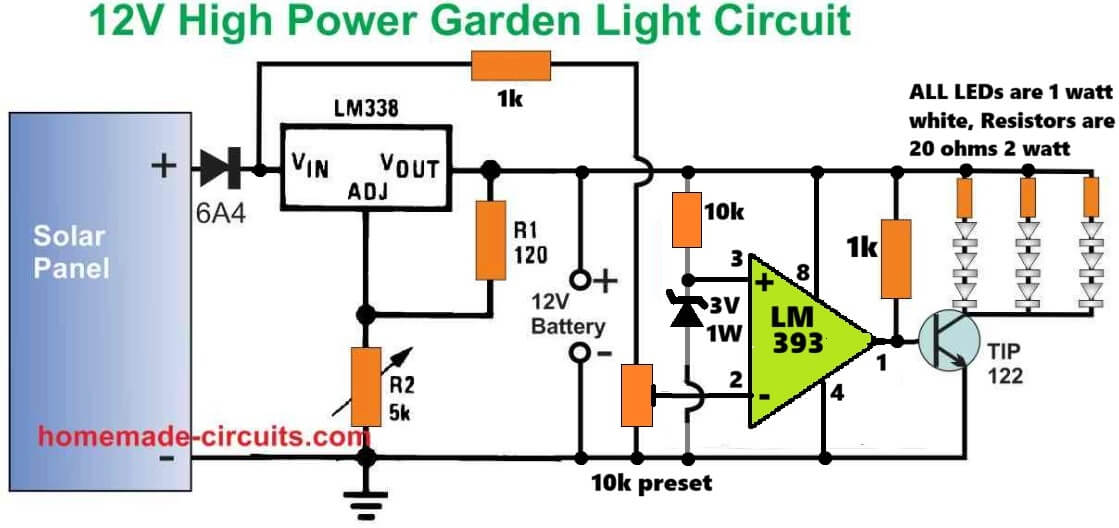
And here’s the full schematic of the design that you have asked….let me know if you have any further doubts regarding this circuit:
Hello.
I am electronic engineer also. I am in Canada know but originally i am Iranian.
I look at your circuits . I don’t work in designing field but i work in repair and service field and i was in one Solar Farm installation in my country . 10 MW .
Best Regards.
Mohammad.
Thank you for your introduction, glad to know about you!
All the best to you…
Good afternoon i did email you previously and thank you for your reply but i am struggling to convert the 6v solar panel with a x3 1.5v rechargeable batteries onto a circuit board having never done this before so want to make sure when i do my first circuit board ad transfer you circuit diagram i will be a lot better infirmed. So is there anyway you can send me a overview of how i would transfer this onto a circuit board if you have the time please?
Hi Kevan,
You will have to connect the 3 cells in series to make them compatible with your 6V solar panel.
However, if this is your first circuit project then I am afraid you will have to first learn how to solder the parts on a PCB.
There are many good youtube videos which you can refer to, to learn how to put components on a PCB and assemble them by soldering.
Please let me know if you have any further doubts…
Hi. I haven’t successfully completed one of your previous circuits with the solar panel yet because the panel has a broken wire and the leds stayed on and flattened my battery.
I’ve now fixed the solar panel, however i wanted to ask whether and if the diodes actually are zenner in this first circuit. “However when dusk sets in the solar voltage begins to drop, and when it drops below the zener diode rating”. I looked up the data sheet for the 1N4007 diode and there wasn’t any mention of a specific reverse breakdown voltage or the name zenner anywhere. Thanks Tony
Hi, I am extremely sorry for the confusion. There’s actually no zener diode in the first circuit, I will do the necessary corrections in the explanation soon.
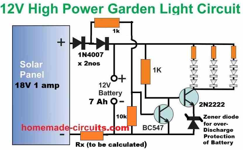
Also, please try the following diagram instead, because in the above first diagram the LEDs will start illuminating as soon the solar panel voltage starts dropping below 4V, which is not good. In the following diagram, the LEDs will illuminate only when the solar panel voltage has dropped below 1V.
Please let me know if you have any further questions…
That was an extremely fast reply. Thank you. I can see that this link to the 18v panel and 12v battery will be very useful in the future as mine and most other general use solar panels for boats, camper vans etc are either just under 20v output or 40v output….and in this linked diagram and circuit i assume the zennr breakdown voltage must be around 11.5v. I will probably try this one later….however, the first circuit was perfect for the little panel i had spare (6v), 4.5v battery from a broken tech piece and a set of led mushroom lights that i already had that were originally powered by 3 series button cell batteries. I’m pretty sure i should be able to tweak the circuit now I’m sure a zenner wasn’t required in this more simplistic circuit. Cheers, Tony
No problem at all, I am always happy to help!
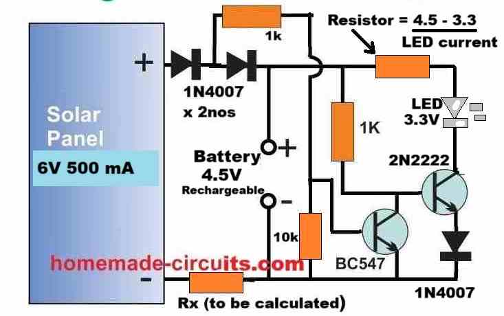
Your are absolutely correct with your assumptions, regarding the previous circuit design.
For your 6V application you can try implementing the following design:
If you can tell me the mAh rating of your rechargeable battery, then I can provide you with the value of the Rx resistor…
Cheers!
Thanks for the new 2 npn resistor circuit, i think the amps coming out of the small solar are pathetic and this second circuit might be more sensitive to this. Two questions that probably come out of my lack of understanding of electronics..1. Could you explain why the first diode coming aways from the solar panel is necessary (i don’t want to lose any more volts than is absolutely necessary…. and 2. The final diode after the 2n22222 transistor looks like a throw back….or forward… to not depleting the battery too much…in which case would this be a 5v zener in reverse? Sorry if I’m seeming stupid now. Inexperience. Cheers
Thanks for the insights! You are absolutely correct, the diode which is connected to solar panel positive is simply not required, because the second diode can handle an accidental reverse polarity situation as well, and safeguard the components.
So you can safely eliminate the diode associated with the solar panel positive terminal.
Yes, the 2N2222 emitter diode can be replaced appropriately with a zener diode to prevent over discharge of the battery.
Let me know if you have any further doubts!
Hi Swagatam, i tried 12v high power garden light using lm338,but i cannot get it work.Please help me to get it work. Thank you.
Hi Vladimir, could you please tell me what exactly is happening with your circuit, I will try to solve it…
Hi Swagatam, Thank you for quick respond. Sorry, i forgot to put a diode like you mention. After this simple fix it is working now. Is it possible to put a diode in your on line site diagam circuit? Thanks again. God bless you!!!
Thank you Vladimir, Glad it is working now. Which diode are you referring to? Is it the zener diode at the base of the lower BC547 transistor?

Hi. the diode is not in circuit. it mention in red under circuit.
“Please remember to connect a Diode between R1 and the battery positive.”
So i did like you said
Ok thanks, understood, yes that diodes is important to make sure that the battery does not self-discharge through the 240 ohms and the potentiometer.
Hi Swagatam, without added diode led’s did not turn on at dark time, that was my problem. But i did not think about discharging battery also with out diode….
Thank you Vladimir,
The actual purpose of that diode is to prevent battery discharge through the LM338 resistors, but even without the diodes the LEDs should have illuminated?
Anyway, I am happy the circuit is now working for you.
Swagatam… I bought several landscape lights and these are 1.2v ni-cad units. They didn’t come with circuit diagrams and two have failed after a week or two. I suppose they could be faulty due to infant mortality and the store will exchange them for new units but it would be nice to tinker with them if I knew the parts layout and specs. Thanks for providing this webpage.
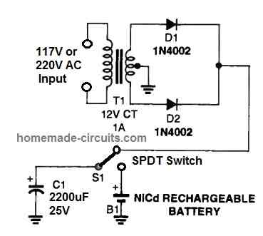
Thank you Ozzie, you can perhaps try the following design to revive the dead Ni-Cd cells and try experimenting with them:
Hi Swagatam,regarding 3.7V Li-ion voltage circuit. I am trying to make solar light powered with 6Ah Li-ion unprotected battery, which will turn on only at night, and only when PIR sensor detects movement. LEDs power should be about 0.5W and I expect ~60lm from them. What is the most efficient way to make this, as I need long last device without additional charging?
I saw all topics for solar lights and PIR sensors, but did not find any that I know how to modify for my requirements. Do you maybe have a PCB design that will fulfill those requirements?
Thank you in advance and best regards,
Tibor
Hi Tibor,
here is the complete circuit diagram that will fulfil all the specifications you need in your design:
Hi Swagatam,
this looks like something I need! Thank you very much for your help!
Also, I want to know why you choose 9V and 1A panel? Isn’t 1A not enough for 6Ah capacity?
And if I want to use 6V panel, whould it still work in this configuration?
Btw. I saw you wrote LED 1W, what will be the difference if I use 0.5W LED?
Thank you!
No problem Tibor, I am always happy to help!
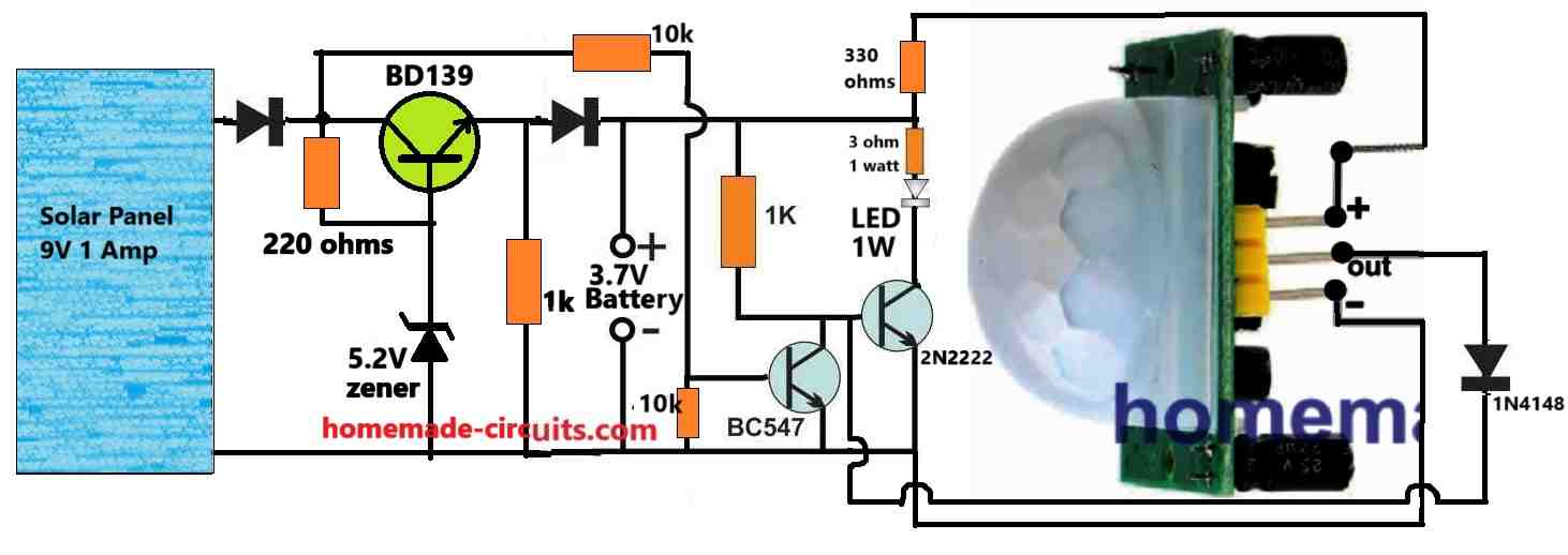
In the shown diagram, the two diodes and the transistor combined will drop around 2.5V, so the panel voltage has to be at least 2 volt higher than this drop.
If your battery is 3.7V then its full charge level will be around 4.1V, that means the solar panel must be rated at 4.1 + 2.5 = 6.6V, but considering the sunlight fluctuations it is recommended to add 3V more to the panel, so it must be around 6.6 + 3 = 9.6V or higher.
Yes, for a 6Ah Li-ion battery 1 amp current is quite low, in that case you can consider adding more panels in parallel and upgrade the input current to 3 amps.
In that case the transistor will need to be replaced with a 2N3055 and the base resistor reduced to 50 ohms 1 watt.
The diodes can be 6A4 diodes each.
Also, there’s one mistake in the diagram. The 1K connected with the base of the 2N2222 must be removed because we want to activate the 2N2222 only through the PIR, and not from any other source.
For the LED, you can use any desired 3.3V LED, just make sure to change the series resistor accordingly.
Thanks Tibor,
To get accurate results you will need a two transistor circuit which will ensure that the LEDs do not turn ON until it is totally dark outside.
An additional LDR might not be required, we can manage with the solar panel voltage for the detection.
I have understood your requirement and will design the entire circuit soon and let you know, with all the part specifications.
Sir: where does one get all these components. Thanks
Hello Leon, you can search for the following phrase, you may find many good electronic stores for buying electronics spare parts:
buy electronic spare parts
Sir: need a circuit board for a LED lite string 3-5 volt dusk to dawn for a cross I am trying to light .Would like a board made in the USA. have a 12 volt solar panel on the cross. Need your recommend as I have failed many times because at 83 years old I have tremors bad and soldering is areal struggle. Thank you
Hello Leon,
According to me, the last circuit from the above article will be most suitable for your application. If you are having difficulty soldering, you can hire somebody to do it for you. Please let me know if you have any further questions.
I’d like to know how to convert a battery Operated garden stake globe into a solar powered garden stake globe (using a dollar store solar-lit garden stake). Is this possible? What should I do?
EB, do you have a dc voltmeter? if yes then we need pictures of your project. if the original light uses two bateries that would be 3 vdc, if the dollar store uses one that is only 1.5 .
I do not know the voltage and current specifications of the units you have mentioned, so it is difficult for me to suggest.
Hi swagatam
I need your help, for making a circuit of AUTOMATIC CUT OFF WHEN SOLAR CELL PLACE UNDER THE SUN AND TURN OFF LIGHT & CHARGE BATTERY. WHEN I PLACED THE SOLAR CELL UNDER THE SHADOW THEN AUTOMATIC LIGHT TURN ON, on battery
Hi Kartik,
Automatic cut off is not required. You can simply use a LM338 IC regulator and set it to provide a constant voltage to the battery which should be slightly lower than the extreme full charge level of the battery.
Here’s the design which you should build:
Thanks Swagatam, Let me try this solution…
Sure, no problem.
I have bought a 3W 6V solar panel what value of diode,resistor and transistor and led bulb should I use for a solar lighting system project. Can you please tell the assembling diagram too.thanks
You can try the following setup:
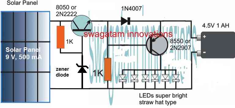
Adjust the zener diode so it creates around 4 V across the battery terminals (without connecting a battery)
The battery can be any 3.7 V Li-ion battery
Hi Swagatam, many thanks for the awesome website and content!
The wife bought some LED garden lights, but they don’t come with solar charging. I’ve decided to try and build the solar charging + automatic dusk toggling. These lights come with an IP44 3x AA enclosure, and I’m wondering if I can reuse them. The LED lights are 10x 0.3W. Based on this, am I correct in thinking I can use the second circuit listed under the “Circuit Diagram” title, without modification?
Cheers!
Hi TJS,
yes you can use the second circuit, however if you find the 2N2907 heating up a bit then you can replace it with a BD140 or TIP32 transistor. If you find the brightness is not optimal, you can try reducing the a 10 ohm resistor or the 1K resistor with some trial and error.
Hi Swagatam, many thanks for the quick response. I’ve taken on board your suggestions for alternative components.
What changes would be needed to use a CL-SM3P cellevia power solar panel? Is it too powerful for this application?
Thank you TJS, can you please tell me the specifications of the solar panel in terms of its voltage and current? I will try to solve it for you.
Hi Swagatam, sure thing. Here goes:
Really appreciate your help!
Thank you TJS,
17V is a lot for a 3.7 V battery. If your battery is a 3.7 V rated then either you may have to use a step down regulator to control the voltage or use a 8 V solar panel instead.
Understood sir. I’ve found a 6V 2W panel. I believe this will work with the circuit we have been discussing.
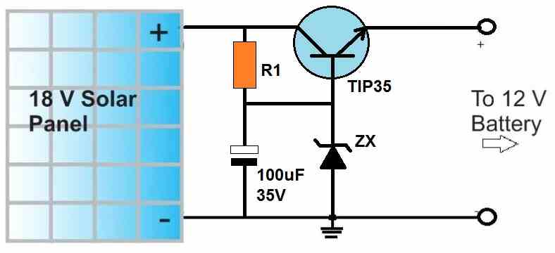
yes, that should be OK, however if your 3.7 V battery would still require some kind of voltage regulation so that it is not overcharged beyond 4.2V. I would recommend the following type of simple regulator. The resistor can be a 1K resistor, the transistor can be BD139 and the zener diode can be selected such that the transistor emitter output generates around 4.2V. Check the 4.2V after putting a load resistor of 470 ohms across the emitter and ground of the circuit.
Hi Swagatam. Sorry, but I’m a little confused. Where do the lights go, in the diagram you’ve shared?
Hi TJS, here is the complete circuit diagram with the regulator. The zener diode value should be selected such that a full charge level of the battery is available across the points where the battery needs to be connected. This must be checked and set without the battery connected.
Hello, I made this system, but the LED lights up too early, where to insert the resistor to delay the LED lighting. Regards
Hi, thank you for trying this circuit….However If your solar voltage drops below 1V then the transistor will switch ON and the LEDs will light up, We cannot do anything about it.
Thank you for the quick reply. My problem is that the voltage is still 3 -5v and the LED is already starting to shine, I will add that the 1 Watt LED, 6v solar panel and 3.7v battery should the 1n4007 diode be only behind the 1k resistor or the 2n2222 transistor also give ?regards. Ps. very helpful site thank you very much!
At 3V you can check the base/emitter voltage of the transistor, if it is above 0.3V then the LEDs might start to shine a bit. To avoid this you can try adding a 1N4148 diode in series with the gate terminal of the transistor. Anode will go to the base and the cathode towards the 1K resistor.
The right side 1N4007 diode is important and cannot be removed. The left side 1N4007 transistor is only to protect the circuit from an accidental wrong polarity connection of the solar panel. If you are sure that the polarity connection is correct you can remove the left side 1N4007 diode
amazing to me your depth of knowledge, did you get most of your knowledge from a certain book? I am very interested in building resourceful projects. Maybe you have a suggested reading? please keep posting all your great ideas.
Thank you for your kind words. My knowledge of electronics has come from books and practical experience. Do let me know if you have any further doubts or questions.
Hi SwagatamRegarding your last circuit “High Power 12V Garden Light Circuit”, could you please advise as to where the best placement of a 12V Zener diode would be for low battery cut off? Would it be between Q2 base and battery +, or would it need to be in series with the 1K resistor and battery positive?
Many thanks for a very impressive site BTW
Thank you Duncan,
As correctly guessed by you, it must be in series with the 1K base resistor of TIP122
So I tried this insertion over the weekend, and it did not work as intended. When the 12V zener was connected, the lighting was illuminated, but very very dim. Even after removing the 1K resistor, the effect was the same.
Any ideas on this for a solution?
In that case you may have to reduce the value of the zener diode. You can try a 11V or 10V zener diode and check the response. However, first you may have to confirm whether the LEDs are illuminating brightly or not without the zener diode. If it does then the problem may be with the zener diode, and you can try using lower values.
Yes, my LED lights do illuminate fully without the diode. But, to give feedback, as you suggested I tried an 11V zener, and this seems to work. Although not 100% what I’d like, as it drops the battery down to ±10.8V which is not the best level to have your battery at.
But I guess it’s better than running the battery completely flat and into irreversible damage. What was interesting is that the diode starts to activate at around 12.2V and starts to put the lights into like a “limp mode”, at about ¾ brightness, then gradually dims until the zener voltage kicks in for total shut off.
Thank you for the feedback and update! It looks interesting, however I guess a simple zener network may be too basic to provide accurate cut-off results. So getting perfect results might not be possible using a zener diode only. Instead, a combination of an opamp and a zener diode might do the job to provide the desired accurate results.
Hi Swagatham,Thanks for the response and appreciate.As you asked me for specification of type of batteries and voltage and amperage. To myself clear I thought it would be more precise if I sent you pictures of the units I have. I have three varieties . Please have look . But it seems there is no way to send photos. 1.AAA 1.2V. 600mAh,NIMH BATTERY, one battery(2) AA 1.2V 600mAh,NIMH ,2 batteries.(3)AA1.2V 600Ah,Ni-Cd ,1 battery. All solar panels. I have AC to DCpower supplies of 5 V DC out put. Or any you may suggest.
Hi Ravi,
You can try two NiMH in series, and connect it with the following circuit:
You can replace the solar panel with your 5V DC input.
Then adjust the 10K preset such that battery points are set at exactly 3V. Do this without connecting the batteries initially. Once the preset is set then you can connect the batteries.
For the LEDs you can use 6 nos of high bright 20mA LEDs in parallel
Hi, My name is Ravi and I am in UK. I USED TO LIVE IN USA ALSO. I have accumulated lot of solar path lights and others. Here in UK climate does not offer sun shire consistently. Hence can charge the solar panels fully. So I now decided to use DC power. I have combination of 1.2 V and 1.5 V battery models. What modification I need to add appropriate resisters/ and some thing else.I WOULD BE GREATFUL IF YOU COULD PROVIDE ME A CIRCUIT DIAGRAMS AND RESISTER VALUES, I WILL SOLDER THEM ON TO THE CIRCUIT BOARD. I AM REASONABLY HANDY TO THIS IF I KNOW WHAT TO DO. IF you feel some other details you need to help me, I will provide. Kind regards. Ravi
Hi Ravi,
Can you please tell me the specifications of the battery. Are they rechargeable type, such as NiCd or NiMH type? If they are rechargeable type then you may need a charger circuit also to charge them from an AC to DC adapter.
i have a solar panel which used to runasmall water fearute the circit got smashed at a house move time the remains suggest it was a simple 1fuse 1 diode system the remains cannot be identified correctly need fuse and diode identified or suitable substitutes solar working ok
What is the voltage and current specifications of the solar panel?
no idea it was bought as a working unit by my son all i can say is the water fountain was a 12 volt unit worked ok in his garden then he moved to oz hence i ended up with it the solar panel has no information on physically its 17 by 12 ins that’s actual solar panel measured inside its housing i have a voltmeter panel shows over18 volts in full sun,thanks for answering
OK, in that case, the fuse amp rating will depend on the amp rating of the load. For example if the max current of the load consumption is 2 amps then the fuse can be rated at 2 amps.
And the diode can be a 1N5402 assuming your panel current is less than 3 amps.
new problem fan not working still works of 12 volt battery solar panel still giving 17 volts as soon as you switch fan on voltage from solar panel drops to almost nothing
It means that the solar panel current delivering capacity is far too less compared to the fan’s current rating….you can confirm the panel’s AMP output capacity by connecting an ammeter across its terminals at peak sunshine.
We’re due to move into a new house in the Spring of 2023 for which I am preparing my “Charlie Dimmock” design for the back garden.
I need to include lighting for the said design, ideally not using power from the grid, i.e. instead using solar power. However, rather than having individual solar lights, I need advice on perhaps having a single solar collector, placed in the best possible position for the sun and a battery storage system from which the garden lights will be fed when the sun goes down.
However, to compound things, we are also considering PV panels to hopefully reduce our reliance on the grid house power consumption, so would it be best to combine the two systems?
Whilst I shall print off the content of your web article, any early advice on the aforementioned would be mush appreciated.
It may be possible to extract the power from the PV panels for the garden lights so separate solar panels may not be necessary for the garden lights.
If you tell me the total wattage of the LED lights and the number of LEDs, I will try to figure out the automatic system and the controller for the LEDs.
Hi Swagatam. i’m EN
I have a question.
For example, if I think I use 50W of a solar cell, is there a way to calculate the specifications of the battery or how many W of LED can be used?
Hi EN,
Can you please tell me the voltage rating of the solar cell, I will try to figure it out for you!
solar Power 30W
Max power voltage 18V
Max power current 1.66A
open circuit voltage 21.6V
Let me know if you need any further information. Thank you
You can use a 12V 7 Ah battery with a LM338 solar voltage regulator set to control the max voltage to the battery at 14V.
For the LEDs you can use 3.3 V 1 watt LEDs. Make 3 LEDs in series and connect 5 of these strings in parallel. Each string must have a individual series resistor rated at 7 ohms 1 watt
The maximum voltage of the solar cell is 18V, but is there a reason why the battery uses 12V?
Also, I wonder why LEDs are used in a combination of series and parallel.
How many hours is the LED light based on this connection?
Using a 12V battery leaves a good margin for the battery to charge even while the sunshine is not at its peak. For LED total forward voltage must be lower than the battery lowest voltage level. With 3 in series, the total forward voltage of the string becomes 9.9V which means even if the battery voltage drops to 11V the LEDs will still remain illuminated. The LEDs will not illuminate if the series forward voltage of the LEDs become higher than the battery voltage. With a fully charged battery the backup time should be around 4 to 5 hours.
The battery should be charged through a LM338 regulator
Hi. swagatam.
Do you have a sample circuit for your explanation?
And I hope to be lit for more than 10 hours using 10 LEDs.
Hi EN,
I have updated the diagram for you at the end of the above post. It will last for 10 hours, using 9 nos LEDs, 1 watt each
Thank you for your answer. I’ll test it.
Previously, the LED was said to operate for 5 hours, but the circuit is a circuit that operates for 10 hours. What’s the difference?
And if I change the specifications of solar cells and batteries, do I just change the resistance in the circuit?
Sure, you can build it and let us know the results.
Previously 15 LEDs were used, and now only 9 LEDs are used, therefore the backup time has increased. These are only approximate values, the actual value can be found only by testing it practically.
You don’t have to change anything in the circuit upto 30 V input. But as the solar voltage is increased, the heat on the LM338 will increase proportionately.
Thank you for all the circuits you proved with your emails, I always look forward to receiving your emails to see what circuit ideas you have.
Many thanks, keep going you should do a YouTube channel I would join.
Thank you so much, I appreciate your kind response.
I have a video channel, you can view it here: https://www.youtube.com/c/SwagatamMajumdar/videos
hie.i would like to design the above solar light cct.can i connect two batteries 3,7 v in series to increase power stored and lighting time
How long does the above light ís on before switching offf
Hi, yes you can use two batteries in series and configure the LED series connection accordingly.
How long it stays ON will depend on the battery capacity and charging conditions
Hi Swagatam.
There’s a question in your circuit.
“a simple voltage follower regulator circuit”
What does 10K preset mean in this circuit?
Regulator? resistance?
Additionally, I don’t have 8050 or 2N222. 135D was used. No problem?
I’ll be waiting for your response. Thank you.
Hi EN, the 10K is a variable resistor preset or a trimpot.
I could not find the datasheet of 135D transistor, so I am unable to suggest whether it can be used or not.
Thank you for answering.
It’s BD135 from Onsemiconductor.
In the above quesiton circuit, do i have to use tow 1N4007? Tow letters were written, so a circuit was created, but the battery does not charge even when exposed to sunlight.
BD135 can be used, You must adjust the 10K preset accurately so that the emitter voltage reaches the full battery charge level across the battery terminals. Measure this without connecting battery. I did not understand what you meant by “tow 1N4007”
The solar panel current must be correctly rated as per the battery specification, only then the battery will charge.
solar panel 6V, 0.35A, Battery 4.2V, 2550mA
Is there a way to send pictures? Mail or another?
Thank you
Did you confirm the 0.35 A and 6 V with meter? Check it with meter it might be less than that. By the way 0.35 amps will not charge a 2550 mAh battery efficiently…it should be minimum 0.5 amps to 1 amp. Pictures are not required, values are enough.
In fact, solar panels are measured lower than 6V.
I don’t know how to approach it,,, but I should study again while looking at the circuit diagram.
Thank you.
The minimum voltage can be 5V, but the current should be between 500 mA and 1 amp.
When the actual test was conducted, the panel was measured at 4.4V and turned on only 3 hours after charging for 3 hours.
I have a question. Why do you use two 1N4007 diodes in the first circuit?
Because of the principle of operation of the transistor?
I ask questions because I lack a lot of knowledge.
Thank you for your answer.
If I have any questions, I’ll ask you more!
Have a good day.
Sure, no problem.
The left side diode is actually not required, it is placed to safeguard the circuit from an accidental reversing of the solar panel polarity. If you are sure you will always connect the panel polarity correctly, then you can remove the left side diode.
Additionally, how do you adjust the 10K preset?
I want to know the formula
You can use voltage divider formula to get the base voltage…
and then add 0.6 to the result….this will be the emitter voltage.
Base voltage = Vin (R2 / R1 + R2)
R1 = 1k or 1000 ohms
R2 = preset adjustment value
Vin = 6V
Emitter voltage = Base voltage + 0.6
Would appreciate if you add costing of components used in the circuit.
I tried adapting these ideas to understand how 200 blue LEDs ((3.2V, 20mA each)) can be lit from one single 1.2V NiMH battery slow-charged from a small solar cell, but I remain mystified. It’s not for any class ((I graduated college in 1979, LOL!)) but I’m wondering, because I’d like to repair 2 light strings if that’s possible. I simply haven’t been able to get from here, to there…
Many thanks in advance for any information or links!
Thank you for your interest in this concept. 200 nos are too many LEDs, and a NiMH might not have sufficient current to handle this. However a Li-ion cell with along with a joule thief circuit might be perhaps able to handle this load
Thank you for your reply!
That must be why the string never worked from the start. Now that I know to not keep struggling to make the original thing work, I’ll start from the ground up so to speak.
Sure, no problem!
Hi SM. I work for a maritime museum and we have a lighthouse which was fitted with a 120v incandescent lamp. I would like to convert this to a pulsating/breathing LED lamp. I have did some research and came across you forum. Thank you for the diagrams. My question is using a 6v agm battery what size of solar panel would be needed? I have read that to charge a 6v battery you should use a 7-9V solar cell. Also any ideas on the pulsating/blinking/breathing feature to simulate an actual lighthouse?
Hi Dennis, for a 6V battery you can try a 9 to 12V solar panel, and use a constant current and constant voltage charger. The current rating of the solar panel can be 7 to 10 times lower than the battery Ah value.
for the rotating light effect you can probably try the following circuit
https://www.homemade-circuits.com/police-ambulance-siren-circuit-with-rotating-beacon-light/
hello, I found this site & followed all the steps but the LED lights could not turn off even during the day. what could be the problem
Hello, connect the transistor base with its emitter manually and check if the LEDs shuts off, if not then your transistor is faulty.
do I basically need to use specifically the transistor indicated on the diagram
It just needs to be a PNP transistor, that’s all
In the picture whose Pictorial Diagram is given, how many volts/amperes is the panel and is the battery 9V ni-cd? Can 9V ni-mh or lithium be used instead of 9V ni-cd battery?
In what range should the mah value of the battery be? thanks
I have updated the diagram with more details, and also provided the relevant calculations.
The battery shown in the diagram is NiCd, Li-Ion or NiMh can be also used. For Li-Ion and NiMh batteries the 10% figure indicated in the R3 formula will change to 50%
Hey, 7.4Volt 2600mah (2 serial 3.7V li-on batteries), how do I set up a circuit for a battery? Can you help me build the circuit? For example, how many volts should the panel be? can you draw a circuit diagram. Thank you
You can use a 12V 1 amp solar panel, and adjust the output voltage using a LM317 circuit to precisely 8.2V and then you can charge your series battery safely.
Hello, I’m trying to design a solar dusk to dawn light using a 3.7v 18650 2400mah battery, a single bright white 60-80lumen light with the smallest solar cell that charges on cloudy days. The light must maintain light atleast 10 hrs at night. The led possibly could pulse at 50 cycles as to save on power and not notice blinking by the naked eye. Thank you.
Hello, you can use a 100 mA or 50 mA straw hat type LED, and use with your battery for a 10 hour back up. The solar panel must e rated at 6V, 1 amp. You will need an auto cut off circuit for charging the battery with this solar panel.
Thank you, would you have an existing circuit diagram?
You can try the last circuit from the following article:
You may replace the P mosfet with a 2N2907 transistor, and replace the 2N6284 transistor with 2N2222
https://www.homemade-circuits.com/battery-deep-discharge-protection-circuit/
How can the pcb pictorial be done on a copper clad board? I have only an inkjet printer and want to build this circuit?
You can refer to this article for the details:
How to Make PCB at Home
dear sir; the above constant voltage circuit designed with 6v battery and 6-8v/2w solar panel, 2 transistors and few resisters and load of (24) .5w high power leds is really great. my question is if I increase the load to (44) .5w and select the a/h of battery to 20a/h also double the the amperage of solar panel would circuit work properly? I thank you very much..
Dear Vj, yes you can definitely upgrade the circuit by suitably modifying the parts, and the battery. You will have to use a TIP127 for the transistor, 10k resistor for the base, the charging current limiter must be adjusted to a value which allows only 1 .5 amp to 2 amp current for the battery charging.
I’m a 75yo woman and have no electrical background, but am willing to learn new things. I have purchased a commercial solar powered pump package with a fixed solar cell. The pump turns on with a manual pushbutton switch. The small electrical storage battery (12v) does not hold enough electricity to power the pump through the hours after the solar cell loses sunlight until the next day. Once the power supply is exhausted, the pump switches off and remains off until the manual switch is pushed again. It is in a remote area, so the pump might be off for several days until I can get back to switch it on. I am making a solar tracking unit to extend the hours that it is in sunlight, which will hopefully extend the battery service also.
Here is my question: Is there a way to use a small solar cell to power a switch that will bypass the manual switch and turn the pump back on when the sunlight is available the next day? If one of your examples above will do that, please tell me which one to use.
You can build and implement the following concept:
Please note that the relay of the circuit will activate ON and OFF momentarily only when the sun light has reached a reasonable peak level. If you want the circuit to activate at a lower peak level of the sun light then you can reduce the relay value to 5V, and also replace the 12V zener to a 5V zener.
Hello Swagatam,
Firstly, top notch support for your ccts. You really are very patient with everyone. Can I ask please, I have a very low power 5v solar cell, how much current loss is caused by the simple single transistor circuit? I presume this one would be the least hungry of the ccts. At the moment I use a switch to feed the leds and automated is definitely the way forward.
Thank you for your time and I hope you have remained healthy through the pandemic.
Neill
Thank you very much Neil for your kind words!
No current would be wasted by the transistor circuit, since the transistor circuit would remain switched OFF. However, a slight current would be lost through the base resistor of the transistor, which would be in a couple of mA may be. You can definitely think of replacing the mechanical switch with a transistorized circuit, with minimal current drain.
Figure 1 & 2 I can’t seem to make it work at all, the same is true for the similar circuit using the 2 transistor version, 2222 & 2907, the mail issues is I can make it light with the battery but it will not shut off the led during the day / charging cycle… Checked and double checked… Help…
Please check the circuit first with a bench power supply, not with solar panel.
With the input DC connected check the voltage across base/emitter of the transistor, it must be 0V, and it should be around 0.6V when the input supply is removed!
With 0V across B/E, the LEDs should be switched OFF, and with 0.6V the LEDs must switch ON
Good morning Sir,
1) What is the advantage of the circuit with the two npn transistor ? Does doubling the transistor increase brightness ?
2) I want to use 14 LEDs (4mm leds) to run for 12hrs with good brightens, using 3.7v li-ion battery;-
a) what should be the capacity of the battery?
b) if I have 2watts 6v solar panels how many can I parallel to charge the battery.?
c) which circuit can I use for this to serve as an automatic solar outdoor(landscape) security light?
Thanks
Hi Ngang, slight advantage is there due to better ON/OFF switching of the LEDs, and better transfer of power to the LEDs.
A 2 watt solar panel will produce 2 / 6 = 0.33 amps or 300 mA current, which means a 4.5 V battery or a 3 V battery can be used having 2 Ah rating
LEDs can be 3.3 V 1 watt single, or 3.3 V 20 mA up to 10 in parallel.
Hello, I have 4 garden lights each one has two 8mm white leds I would like to use only one solar panel,two service all four lamps,but dont know what
size or wattage or voltage to use.
I hope you can help…………Frank
Hi, assuming your LEDs are 50 mA each, and the two LEDs are in series in each of the modules, then for 4 lights the total current required will be 200 mA. Now to illuminate this 200 mA lamp for 10 hours will require a battery rated at 2 Ah or 2000 mAh.
Your solar panel must be around 3 amps and voltage equal to 10 V, with a 7V controller
Thank You..
Frank.
Hi Namaste Swagatham
I just beginning to learn and do some hobby during Covid-19. I have solar powered pedestal light on long post. The switch failed due to water leakage. I am trying to replace the switch. But I need to replace the resister to reconnect the wires. I cannot recognise the resister. It is tiny blue resister connected to terminals. This is because the switch has three positions. Semi / Off / Full. The switch has six terminals three on each side.The resister is connected semi and off terminals. Perhaps I I could send photo, but do not know how to include in this comment. Please help. I have also other small hobby projects which I will let you know. Thank you very much. I am from UK, SENIOR CITIZEN. RAVI
Hi Ravi, without seeing the image it can be difficult for me to understand the fault. What you can do is, upload the image on any free image hosting site online, and provide me the link, I will quickly check it out and try to solve it for you….
Hi Swagatam,
I have found several of your articles very interesting and delightful. However, I have a project that is VERY unusual and have not been able to find a circuit to solve my problem.
I am attempting to back light a lithographed photo that is mounted on an outdoor plaque. I want to use a single white LED (or a single 5050 RGB strip light LED) to backlight the lithograph. Normally, I could use a solar powered Garden light circuit, however I need it to stay lit during the daytime AND night time and still charge a battery (1.2V NI-CD) for the nighttime use. I can use 2 solar cells, one for daylight use and the other to charge the battery for nighttime use, However, I am not sure of the best way to isolate the two solar cells so one powers the LED during the day while the other charges the battery and then at night switches to the battery. Any help would be appreciated. I am an electronics tech with some engineering (self taught) background, but this seems to be eluding me for some reason. I hope you can help. Thanks in advance.
Thank you Tony, glad you found them interesting!
I think two alternating cells may not be necessary, instead multiple cells could be attached in parallel which may be rated to keep the LEDs lit up for 24 hours with each charge. Similarly the solar panel may be rated to ensure both the cells are optimally charged each day.
If you provide me the LED current and voltage specifications I can provide the estimates for the solar panel and charge control specifications
Alternatively, if you think two alternating cells would be a better choice, I can suggest an appropriate design for that also….
Thanks for that it’s really worth to query the designer appreciate it very much
It’s wonderful finding you on Pinterest
Rgrds,
Eduardo
It’s my pleasure and happy to help!
After reading I’m trying to find that zener diode describe but not available in anypart of the schematic diagram pls give details
Thank you for sharing
In the second last diagram, the 10k preset was not included in the original initial diagram, instead a zener was put in that area for getting a fixed output at the emitter side. If you don’t want the preset for customized adjustment you can replace it with an appropriately rated zener diode
I’m new to this website. It appears to be exactly what I need.
Home / Mini Projects / Simple Solar Garden Light Circuit – With Automatic Cut Off
This is a genius little circuit and would be perfect for my Japanese lantern. Is the PCB board available?
Hi, Thanks, and Glad you liked this website and the circuit! However, sorry I do not have ready made PCB for this project, but since the design requires very little parts you can easily assemble them over a small veroboard or a strip board.
Hi. Found this site about 2 weeks ago and built the circuit. First time I have done anything similar for maybe 50 years!! I was a bit apprehensive. However the circuit works well. I am quite happy with it. One problem the LEDs light up too early. It is still light. I am using 4×1.2v Li-ion batteries. I reduced the 10 ohm resistance to 5 ohms. Is there away to prevent the LEDs lighting up before it gets dark? Thank you for firstly the circuit and secondly the time you spend answering queries
That sounds amazing and Glad you could make it successfully. The early switch ON could probably be prevented by upgrading the circuit through a couple of more transistors as shown in the following image:
Hi Swag,
In this circuit, can I replace the 6 LED’s by a single of high Power, say 1W, 3W or 5W?
If so, which changes can I made?
Best Regards.
Nelio.
Hi Nelio, yes that’s possible, the formula for the series resistor is:
R = (Battery Voltage – LED Fwd voltage) / LED Current
Hi,
You are refering the first circuit.
I was considering this one :
Solar Pathway Light Circuit with Constant Voltage
Nelio
Yes I was referring to the first circuit, in the pathway circuit you may have to connect a resistor in series with the collector of the LED transistor. This resistor should be calculated using the previous formula
Ok.
Thanks.
Best Regards.
Nelio
Glad to help!
https://drive.google.com/drive/folders/1oCAPL9J53O0QZP7SXJnlNtnkq8NQ9QoY?usp=sharing
I have reverse modeled the board. If you are curious to see it, you can find it here as .jpeg file. Most of the elements I was able to read, but not all.
It is difficult to understand the diagram in this form, please draw it in proper schematic form with correct symbol and pin direction, I will try to figure it out.
Hello Swagatan,
I found your site by accident a week ago and I`m completely hooked up.
I have an old solar lamp that uses 1.2V Ni-CD battery and 1 piranha LED. It has an LDR to turn it ON/OFF, however I notice that even without it, it turns ON/OFF if the Solar Panel is illuminated.
Can you reverse engineer this board, if I provide you pictures of it, as I want to make myself more of these DIY. It says 3033 on one of the elements, has SGL0047-3033 printed on it. I could not find anything on the internet about it.
Thanks for your answer in advance.
Thanks Dimitar, I am glad I found my sire useful.
I think an LDR is not necessary for a solar automatic LED circuit. The first circuit from the above article will also do the same. When sufficient light applied on the solar panel, the LEDs will remain OFF, and they will switch ON when the light becomes weaker.
Thank you for your fast reply, Swagatam.
Is the first circuit going to work at 1.2V, or must it be 4.5V, 3 NiCD/NiMH batteries in series?
Yes it should be 4.5V. At 1.2 V the LEDs will not light up.
I understand.
The solar lamps I have use 1x 600mAh 1.2V NiCD battery and powers a 1W warm white COB LED. I believe they are rated at 3.2V. It lasts about 5-7 hours, depending on the amount of sun during the day.
Can you propose a way to achieve this? Do you want me to send pictures of the board? If yes, how?
P.S. My bad, it does have an inductor, it does use a joule thief.
OK, so in that case you can use the diagram which I suggested in my earlier comment. It has a feedback loop which will switch OFF the LED during day and switch ON during night at 1.2 V supply
Thank you for the great advice, Swagatam!
I found the joule thief circuit on your site, but what was interesting to me is that this solar lamp uses no coil, only a couple of resistors, diodes and transistors.
Images won’t be required since it will be difficult to identify the parts and the layout from the images.
Instead you can try the following version which uses a joule thief circuit for boosting the 1.2 V to 3 V for the LED:
If the LED doesn’t light up with a 1.5 V cell, you can try swapping the terminals of the winding between the transistor base and the 1K resistor.
Sounds like great systems. I am not however looking to build a system but buy a ready made system for a large garden area where I can plug in various low voltage garden lights or Christmas lights. Any suggestions? Getting tired of the cheap solar lights from the hardware store and too far to run 120V. thanks.
Thanks, please provide the LED specifications and the connection details that you wish to use, I’ll try to figure out the required set up accordingly
I have made 40 W street light solar circuit I m working in offline solar inverter manf company I m not getting desired output 2 V instead of 12V but cut off low & high is working properly.
I could not understand your question.
Sir I have made a circuit with help of your diagram for 40 W solar street light circuit I m able to adjust low & high cut off but sir I m not getting Required output when solar voltage is given I m getting only 1.9 V max
Dweep, please show me your exact schematic so that I can understand it…upload it to any free image hosting site and provide the link here….
Hi Swagatam –
thank you for all the information here! I’ve made some simple LED circuits before, but I’m new to solar. I am making a night light for indoors – the LED doesn’t need to be very bright, but there won’t be as much sunlight to charge it. Can I increase the size of the solar panel to maximize the charge? Would I need to worry then about overcharging the batteries if the panel got direct sunlight?
Thank you Hannah, yes you can increase the solar panel size for maximizing the output, but stronger sunlight may harm the battery in that case. If you can provide the battery specifications, I can suggest the controller circuit for you.
Thank you! I haven’t bought my batteries yet, but I was thinking about using 2 Kentli Li-on rechargeable AAs – – they output 1.5v 2000mA. I have some flexibility in my design so I could use larger batteries, but I’m not powering much – just one standard brightness white LED. I’m mostly interested in longevity – if possible, I’d like to set things up so the light runs for at least 5 hours even if it’s not charged in direct sunlight.
As per the given specs the battery seems to be quite powerful and has a built-in over charge cut off system so it cannot be harmed by the panel anyway.
You can use a 6V 5 watt panel and connect its output directly to the battery for charging. Since the current is only 5 / 6 = 830 mA and will continue to drop as the sun goes down, the voltage will effectively therefore drop to the desired battery level and keep the battery topped up always.
I have a garden PV light PCB but it does not have any visible ICs, transistors, or non-LED diodes unless these components are hiding under a hard circular mound of dried adhesive or maybe heat sink material that is on the side opposite the components. I wish to understand where the conductor tracings connect but this is hidden under the mound. (I would send my photos.) I have minimal circuit analysis skills and hope this simple PCB will be instructive.
You can upload the pics to your google drive and share the link with me here, I’ll try to figure it out
Wanted to say thanks! Will an 18v panel be too high of a voltage (at really low current) for the base of the pnp? I assume the higher (than 12.8v battery) voltage is what turns it off during the day.
Thanks!
Hi,
I’m making a 12.8v battery powered, 4 led (in series) solar light, at about 250 mA (the LEDs require only about 2.8v each and can handle over an amp)
I just want to know if the transistor can handle 18v or so from the panel (at very small current). I’m not sure how it works. The higher voltage from the panel (which is more than battery voltage) must turn off the transistor at the base?
Thanks.
Hi, yes the 8550 or 2N2907 will easily handle 18V. The transistor will remain switched OFF as long as the base/emitter voltages are at equal levels, meaning the difference is 0V
Sir,
I can’t see the updated diagram for lithium ion. is the 10 ohms resistor is eliminated in the lithium ion version?
Hi, is there a substitute for tip122 transistor? Thanks for your input
There’s no easy substitute for TIP122
Hey, hope all is well and safe with you and yours. Just wanted to mention that I received the tip122 transistor and got busy putting that circuit together. The issue I have encountered is that the light doesn’t remain on, it turns off then when battery gets taken out and put back in it doesn’t remain on just a flicker. The solar end of it works. It does what its supposed to. What am I doing wrong. Oh, and by the way I’m using a string of-4.. 1w cob led lights in parallel and using an 8 volt battery.
Hey, please remove the solar panel and then check the response. Make sure the battery is optimally charged for the LED. If still it flickers then your transistor may be faulty, or there may be a loose connection somewhere, or the battery may be low.
There was no reply option on your last post. So I’m using old cmment. Anyway, this is the schematic I’m referring to; https://drive.google.com/file/d/1bhto9JCa2C1U4eUBw-aZwhkNlDBJbpNm/view?usp=drivesdk
Does the preset adjust the voltage coming in the solar panel by the way? Not sure why I’m only getting 2.5v coming from light output. I’m using a 7.4 2s2p 18650 with BMS. For this project.
Mario, Yes the preset is used for adjusting the voltage to the garden light circuit. The voltage must be higher than the battery voltage. You must disconnect the base of the PNP transistor and then adjust the preset to get the required charging voltage across the 1 K resistor. Once this is set you can join the PNP base with the 1K.
And remove the BMS and connect a separate battery while testing.
If you are geting 2.5 V then definitely there’s something wrong with your panel or the NPN circuit, or may be you are not following the instructions properly which i am suggesting here.
Swag, sorry for not replying sooner. The 6v multiple schematic is working perfect now. My question is about the one with the 10k preset. Is this the correct one?
https://drive.google.com/file/d/1bRO_ebrUBzruoMYWI98CEK4SO3ml1O5B/view?usp=drivesdk
I am only getting 2.5v on the out for the led lights and the solar part is not working properly. I’ve checked connections over and over and still not solved it.
…yes the preset is OK…still for confirming you can check the resistance across the pair of pins which are arranged on one end of the preset, opposite to the single pin on the other end.
Thanks Mario, which 6 V multiple schematic are you referring to? Did to check the output by removing the solar panel entirely? If it is not working after removing the solar panel, change the transistor and check again?
What I encountered was when the i completly darken the panel the light simply turns on then off leaving 1.5 volts output. But if I slowly turn panel over and leave it half way light remains on and getting 3.7v output and the lights remain on and glowing nice and bright. Any suggestions. Thanks
Please remove the solar panel completely and then check the LED response. If the LED flickers then certainly there may some problem with either the diodes or the transistor, or the resistor or the battery. If not, then you can replace the solar panel with an ordinary power supply and check again.
I see, well I tried. Will definitely order me some of those. Can’t wait to fiddle around with these circuits. I have tried many circuits from YouTube videos but for some reason or another the lights turn on at dusk as opposed to dark, therefore draining battery way to early. I noticed on some of your circuits there being 2 IN4007 diodes. Is that accurate? Just wondering. Thanks for all you di, its awesome to see someone take the time to help out us noobs and DIYERS. Have a great one.
The lights won’t turn ON until the solar panel voltage became 1 V or lower, that will happen at extreme dusk, but not at night. For night time switching you may have to use a delay ON timer with the circuit. Two 1N4007 is fine considering the ease of making and the solar panel being 9 V or 12 V plenty of voltage available for the 2 V drop.
Got it, that explains it and makes perfect sense. The 10k preset resistor you mentioned on the 6v circuit, is that a mini potentiometer?
That’s a preset, not a potentiometer, it is intended for a one time voltage setting.
the second last circuit can be used for Li-ion cell. yes the 10 ohm is removed otherwise the Li-ion cell will never get charged.
I have tried your circuit, especially in figure 5, with 24 led a battery capacity of 6 volts 4.5 Ah / 20 hours, there is a problem that I experienced, transistor tip 122, very hot, fortunately I added a cooler, I used 12 volt solar cells, what I ask, could the resistor that is 1k in size be replaced with 10 k of which leads to the bc 547 transistor and tip 122 ?, thanks for the help
yes 1k can be replaced with 10k which will dissipate less current and heat. 10k should work since the TIP is a Darlington BJT with very high gain
I am looking to make large quantity of reading lights for students in a village. I am thinking of using solar panels station at school to charge the batteries. I plan to use LEDs. I like to have the high school kids build it themselves, with some training. So, I like to find a simple circuitry based design with very few parts. I am an electrical engineer, I will be teaching them how to build them. I also need parts cheap. Any suggestions of where I can find what I am looking for.
Please provide the specifications of all the parameters so that I can suggest a suitable design. Or you can tell me the appox budget for each light, I’ll try to figure it out!
Greetings Sir;
Thanks very much for this article. I have tested it and works great.
The problem I am facing is, even after charging the whole day, it runs down before morning. (8 hours only).
I am using:
1) 7Volt, 2.5wat, 0.35A solar panel,
2) 3.7 Volt, 2600mA, 18650 Li-on battery (1 nos)
my multi-meter reads 80mA and 3.08Volt when circuit is in operation
Thanks
Thanks Ngang, glad to know it’s working! The 0.35A seems quite less for a 2600mA cell to charge effectively. It should be at least 1 amp at 4.2V for the cell to charge in 3 hours.
But at 0.35 A also the cell should charge fully but it may take around 6 hours for this.
Are you sure your 3.7V cell is getting 0.35 amps? Connect an ammeter in series with the solar panel positive to check this, I doubt the panel might not be supplying this much current at 5V.
The best way to confirm this is by testing the panel’s short circuit current by connecting a 10 amp ammeter directly across the solar panel terminals at peak sunshine…the result will give you the data regarding the panel’s max current output
Hi Swag,
If I use 3 batteries in parallel how many LED’s can I use?
Best Regards
Nélio
Hi Nelio it will depend on the battery Ah rating and the LED current rating. Typically the total LED watt should not exceed 50% of the Ah rating of the cell, for a Li-ion cell.
Hi Swag,
I have 3 4.5V 1AH SLA batteries, connected in parallel which will give 4.5V 3AH total.
Best Regards.
Nélio Abreu
Hi Nelio, since it’s an SLA battery, the load should not be more than 1 amp, therefore you can use any LEDs whose total wattage may not exceed 1 amp, and for this the transistor will need to be at least 2 amp rated… a BD140 on heatsink will do
Sir I not understand 8050transistor.pls explain 8050 and how its use in this ckt
Please check any online datasheet of 8050 transistor for the pinouts and other details, you can also use 2N2222 instead of 8050
Sir,
Thanks a lot for your prompt help.
Thanking you for your time,
you are welcome!!
Sir,
I have compiled the part list. May I request you to please confirm if any changes are required:
1. Solar Panel = 2V 380mA
2. R1 = 5K
3. T1 = BC547C
4. R2 = 100 Ohm
5. T3 = BC558B
6. R3 = 1.5K
7. T2 = BC547C
8. R4 = 20K
9. P1 = 20K
10. 1.2V rechargeable cell
11. R5 = 10K
12. R6 = 13.2K
13. R7 = 100k
14. R8 = 10K
15. T4 = BC547B
16. R9 = 200 Ohm
17. R10 = 10K
18. T5 = BC547C
19. R11 = 1K
20. T6 = 2N3904
21. R12 = 10K
22. T7 = BC547C
23. TR2 = 40
24. R13 = 200 Ohm
25. T8 = BC547C
26. Cluster of 9 white lights in series.
Can you please tell more about component at serial number 23. TR2 = 40?
Thanking you for your time,
Vishwa, it looks OK to me.
TR2 is the boost coil. 40 is the number of turns for both primary and secondary using any super enameled copper wire which fits inside a torroid ring. For more on this you can refer to the following two articles:
https://www.homemade-circuits.com/8x-overunity-circuit-using-joule-thief/
https://www.homemade-circuits.com/1-watt-led-driver-using-joule-thief/
Sir,
I have a 3w ,6v solar panel.the maximum current = .34a as per the maufraturer & 6v/4.5ah SMF battery. I am new in electronics.pls suggest that can I go with the PCB which had provide you above without any changes.if need,what would be done.
I have 6v 3watt solara panel,6v 4AH battery,5nos 8mm straw hat led fwd voLt 3.2 to 3.4 & 150 amp.
Please suggest for the both resistance value/ cicuit
your solar panel voltage should be at least 8V to 9V otherwise the 6V battery will never get charged.
resistor value can be a 4 ohm / 2 watt
Sir
How much led (8mm straw head
.5w 20ma) can be used for 12 hour
If the battery is 1 AH rated, you can use 5 LEDs in parallel, and illuminate for 10 hours approximately.
Ananta, your panel and battery are OK and can be used for the mentioned circuit, but I cannot guarantee the PCB layout because it was designed by somebody else…so please verify it by comparing it with the schematic
I want to ask again
1. do we have to worry about over-charge when using lithium battery even-though we provided voltage regulation?
yes you have to worry about over charging if the output is set at the maximum charge level of the battery….if it is fixed at slightly lower than the full charge level then you can keep it connected forever, without worrying.
thanks a lot in advance.
Hi swagatam I have a couple of questions
1. do we have to care about overvoltage or current protection when using lead-acid battery ?
2. when the battery got full during the day time, wouldn’t it affect the battery’s health and life-span due to absence of auto-cutoff feature?
Hi Abba, you must care about the over charging factor for all batteries and you must not keep it connected permanently with the source. In the above design we are assuming that the battery will not charge fully during the course of the entire day or rather we have to select the parameters in such a way that the battery is able to charge only upto 60 to 70% maximum during the daytime.
Does a 1 Ah battery mean that the battery will provide a current of 1A over the time span of 1 hour?
One of your earlier replies:
1watt LED x 12 hours = 12 watt hours will be the led consumption
12watt hours / 12V batt = 1ah battery will be sufficient, so 5ah is more than enough.
Here you say that for 12watt hours you will only need a 1Ah battery. I'm a noob so correct me if I'm wrong but doesn't this mean the battery will give an amount of 1/12=0,83A for 12 hours?
yes that’s right, but in the most ideal conditions.
I meant to say 1ah is correct as per the calculations, and 5 AH battery will be sufficient, practically 1 ah will not be good, although technically it may look OK
Verified Build, "Solar Garden Light Circuit with Constant Voltage". Work Great, Thank You!
If I'm using a LI-ion battery do I need to worry about a low voltage cut off?
I am glad you could make it successfully.
yes you will have to worry about the over discharge,in that case you can build the following concept, with the above.
https://www.homemade-circuits.com/2016/05/solar-charger-circuit-using-transistors.html
Hello Sir,
Please suggest me the complete circuit diagram of automatic garden solar led light for:
* Super Bright 8mm Straw Hat 0.5W/3.2V-3.6V (100-120mA) X 2 Nos.
* Lithium Battery 18650. : 3.7V/2600 mah
* SOLAR PANEL Cell: 5V/ 500mW
Thanks,
Please see the updated diagram at the bottom of the article, you can use the concept for your application…
Hi Maulik,
I'll update the circuit in the above article soon….
dear i want make 20w LED with solar can you please describe me which circuit and parts i use
please provide the voltage or the current specs of the LED, or both….
Could you please tell me how can I modify your circuit for my application? > wd-design.de/schaltung.png
In my circuit remove the 10 ohm.
replace the battery points with your PCB's input (+)(-) points.
replace the LED points with your Arduino input supply points.
Sir I assembled this circuit. But I assembled 3lights, providing 6volt 4.5ah battery at one place and connecting all light by cable approx 3meter distance. I used 3 no 8mm hat straw for one lights. My question is when I checked voltage at end off cable shows 3.2volt I don't get this reason. How to solve this? Because of voltage drop light illuminates very low.
…the wire resistance can also be the reason for the issue…
Ashok, please check the voltage across the collector/ground of the circuit without the LEDs connected, if you see correct battery voltage here, then the problem could be with the current consumption of the LeDs that may be causing the drop in voltage.
Hi, Happy to see my garden light working!! Thanks a lot for the circuit.
one query ,what is the use of LHS diode connected directly to solar? Can the circuit function efficiently without it? Since my solar panel is only 5.5V ,battery charging is seeing 2 diode voltage drop 0.7+0.7=1.4v. Is there any modification I can do?
Navaneeth, TIP127 can handle upto 5 amps, so you can easily use it for your panned application, but make sure to put a large heatsing with it…
I am glad too it's working for you!! you are welcome!!
the LHS diode is only to protect the circuit from accidental reversal of polarity, meaning if by mistake the solar panel is connected oppositely.
yes if you are sure you won't make the above mistake then you can definitely remove that diode…
Hi, I have to do a similar project you make here, but I only have a 6v 140mah 0.6W solar panel, and absolutely no knowledge about how to choose components. Can you please help me out in order to make this work out with the panel I have if it's possible? Thanks in advance.
In the second circuit, remove the right side diode, remove the transistor, remove the 1k resistor….now connect the switch terminals in series with the line which was going through the transistor to the positive.
that's all
the battery can be any battery whose voltage may be a few volts lower than the peak level of the panel…and the AH rating could be 3 or 4 times higher than the amp spec of the panel.
Sorry to bother again, but I showed the system to my teacher and He said that a on-off switch will suffice instead of the automatic day-night switch, can you modify this system for me with that in mind? The solar panel is still the same I said in the first comment.
As for the battery, I didn't find the one in your system to sell here. Do you have any suggestions for a more commom type?
Many thanks.
Hi, you can try the second circuit from the above article with your panel, it will definitely work.
In this circuit the led starts glowing as soon as the SP voltage drops below 4.3v ,can u modify this and make the led glow when SP VOLTAGE drops below 3v or near to that
you can add the following circuit with the panel for acquiring the mentioned feature
https://www.homemade-circuits.com/2013/05/low-battery-indicator-circuit-using-two.html
Thank you Sir.
Thank-you,ihave tried 8550 and it works well.but led burns before it becomes dark.kindly suggest changes to be made.
If you have used the series resistor correctly then the LED will never burn, please make sure you have connected a correctly calculated resistor.
BC547 will not work, it should be a PNP and rated to handle 1 amp for the power LED, you can try 8550 or 2N2907 transistor with an identical set up as given above
you will also need a battery, preferably a 3.7 Li-ion
Many Thanks. I agree. These type of special ICs also runs at particular frequency ( Even though the Leds blink , our eyes can't detect) there by reducing battery consumption. Can you help me in incorporating the circuit?
Thanks, the frequency is used as a part of their buck or boost converter circuit which efficiently reduce or increase the voltage to the LED as per the LED specification….that's the only purpose of the involved frequency.
A LED will always require a constant DC with the correct V and I specs for illuminating at the optimal level…if its applied with a pulsed DC then its light will also dim or reduce proportionately
Could you please try designing more efficient circuit like one using qx5252 (solar driver) , where it can light longer and has battery protection form discharge and overcharge?
I already have many efficient and easy to build battery charger circuits posted in this site…you can find them under the "battery charger" category. I normally avoid using special ICs because they are mostly not available in all places and tend to get obsolete overtime.
no changes are required…
you can use any other differently rated battery also, just make sure the panel and the LEDs are also appropriately matched with the battery specs
sure you can try it out. there is no overcharge feature in this design for the sake of simplicity…
this is a cheap circuit so a charge controller cannot be expected for this design, although one can include it if it's felt important by the user.
here the charging current of the panel is matched with the batt specs such that it charges the batt to around 70% until it's dark…with this consideration the charger controller is eliminated for this design
the indicated resistor actually acts as a limiter for the battery, not for the LEDs, because LEDs are assumed to be having the forward voltage fixed in accordance with the battery voltage so no resistor would be required for the LEDs essentially.
But if the LED series FWD voltage is not calculated as per the battery voltage then the strings might require their own calculated limiting resistors
correction:
the formula should be as given under:
R = V/I
Hi, you can use the above circuit for your specific application without changing much….except the transistor which could be replaced with a TIP127…the resistor won't be critical with this transistor and anything between 1K and 22K would work satisfactorily.
you can use any battery as long as its voltage is compatible with the LED string voltage…nothing will need to be changed in the design….however the 10 ohm current limiter might require a recalculation for a given battery.
the following formula could be used for it
V = I/R where V is the supply voltage and I is specified safe charging current rate of the battery
Hi Sir,
Thank you for sharing this circuit?
I have two questions
1) is it okay to continuously charge a battery. Normally for 12v batteries we have a charge controller. I didn't find too many for batteries below 12v. Why is that ?
2) is it possible to add a charging led indicator ?
Hi,
this is a cheap circuit so a charge controller cannot be expected for this design, although one can include it if it's felt important by the user.
here the charging current of the panel is matched with the batt specs such that it charges the batt to around 70% until it's dark…with this consideration the charger controller is eliminated for this design
Sir good day to you
May I use BD140 transister. What can I do to change this circuit ? My requirement one 3w led and battery type 6v4.5 amp
Thank you sir
Hi Rajkumar, what is the voltage rating of the 3 watt LED?
BD140 might not work, use a TIP127 instead
Dear sir,
Good day to you May I use 4.5v 2A battery and 8 smd 5050 led (150ma) . what will be changes for this circuit .
Dear Satheesh,
4.5V 2ah will not be able to support 8nos of 150mA LEDs for too long.
8 LEDs in parallel will consume 1.2 amps, which will drain the batt within 1 hour
yes it will be harmful for the battery to use a higher rated panel….you can put a 7806 IC after the panel supply t0 drop the supply to 6V for the circuit and the battery
Does it matter how high the solar panel voltage is for recharging the batteries? Will using a 12v solar panel damage the batteries when charging them if the batteries only output at like 5v?
Thanks! awesome post
good day sir
i made the solar garden lamp and it working well i just want to know how can i increase the sensitivity of the circuit so it will light up when sunlight really fade out
and i am using 3.7v li ion battery any problem realted to over charging since there is any control circuit
thanks
john
Hi John, you mean you want the LEDs to illuminate when it is almost dark? to implement that you may have to add another transistor stage with the above shown design.
to avoid over charging we can dimension the 10 ohm resistor value such that it charges the battery almost fully by the time the sun is about to set….
thankyou sir for the promt reply
can u help what vaule of resistor to put ( i am using 8v 200 mill amp solar panel and 4x 3.7v (18650)
in paralle)
john
what is the mAH rating of the cells together or for each?
anyhow it seems the 200mA from the panel could be quite low for those cells, and no resistance should be used in order to allow some charging of the cells throughout the day….but a resistor should be included with the LEDs for safeguarding them, as per their rating
Ahhh ok. Light bulb just came on. thank you.
It's for biasing the transistor…so that the transistor is able to sense the voltage level from the panel and switch the LEDs ON or OFF?
Hello. I hope I'm not to late for this question period. I am a total newbie but non the less find this fascinating and confusing. What is the purpose of connecting the line with the 1K resistor from negative to the positive in the first place?? even if "It would hardly dissipate anything" How can that help anything?
Hi, how can I modify this circuit with a timer so that the light turns on for about 3-6 hours after dusk? thanks
current from battery (+) enters the emitter of the transistor, comes out of the collector, enters the LEDs and returns back to the battery (-)
Can you also explain the exact flow of the current from the battery to the LED's, because I'm confused where the current goes after it passes through the LED's. Does it go through the transistor and back to the battery? If not, than what is the purpose of the transistor? Thank you.
you can use the same configuration that's shown above with the following modifications.
use a 4060 based timer circuit.
remove everything from the existing base of the 8550 and connect the base of the 8550 transistor via a 1K resistor to pin3 of the IC.
connect pin12 of the IC to ground via a 1M resistor, and connect a link from positive of the panel to pin12 of the IC.
set the R/C values of the 4060 to get 4 hours delay.
also connect a 1N4148 diode from pin3 to pin11..cathode to pin11
that's all
Hi, how can I modify this circuit so that the light turns on at dusk for about 3-6 hours? and where would I place the timer? thanks
Sir, This is exactly what I need except that I need to use a 15 watt 17 volt solar panel with an output of .89 amp. What components do I need to replace in order to run this solar panel? I'll be charging 2 or 3 18650 batteries in parallel with a 2500mah capacity each. thank you in advance.
Can you share the diagram
Maruti, for charging the mentioned cells you will need to eliminate the 10 ohm resistor and short it with a wire link.
make sure you connect the cells in series and not in parallel, since each cell is rated at 3.7V so 3 in series would require 12V to charge them fully and the 17V panel would work good since it's quite low in current compared to the required 2.5AH rating of the battery.
the transistor and the 1K resistor are related to the load not with battery charging…so will depend on the load specs,
Hello Swagatam
Your site is of great help.
I have a query in above circuit.
What is purpose of 10Ohm,1/4W resistor? How does it act as current limiting resistor?
My understanding was resistor was added for voltage drop in battery voltage of 4.5V to LED spec voltage.
Can you provide the voltage/current/power of LED used?
hello Kancharla, it's calculated in this way:
R = 4 – 3.3 / 0.3 = 2.33 ohms
4 is the batt voltage, 3.3V is LED fwd V, 0.3 is the LED current
watt = 4 – 3.3 x 0.3 = 0.7 x 0.3 = 0.2 watts,
1/2 watt is selected for more safety
Hello Swagatam
Can you explain me on how you came up with 2.5 ohm, 1/2 watt resistor?
Hello Nishanth,
3.6V/1000mAh will get drained very soon with a 1 watt LED, it should be at least a 2AH battery.
you can use a 2.5 ohm, 1/2 watt resistor
Hello Swagatam,
Thanks for reply.
I am planning to use single 1 Watt LED (3.2 V, 350mA), so what should be resistance value and wattage of resistor?
Can i use 3.6V, 1000maH battery?
the LEDs can be 5mm/ 20mA type white LeDs
thanks unknown,
the 10 ohm resistor is for providing some sort of current limiting to the attached battery while the solar voltage is available, and it also acts like a current limiter for the LEDs while the solar panel voltage is absent and the LEds switched ON.
.
Ahh thank you I though it was a pnp transistor. But since it's not is there a way to know just by the label number if it is?
The label will not inform regarding its polarity, you may have to refer to its datasheet online to learn the details….
I should also be able to include a picture if you think that would be helpful
Hello, I liked your schematic because it appeared to be very straight forward, however when i went to make it for myself the LED lit up but would not turn off when light was exposed to the solar panel. when looking for transistors i could not find the exact transistor you call for but i did get a 2n2923 transistor i thought would work. since this is the only active component I'm not sure if the problem could be there or somewhere else. since we are using a battery pack for 8 double A's that should cause it to act as a 12v battery we are using a 750 resistor along with the 1K resistor. currently there is only one LED connected and I believe everything else follows the schematic exactly. Any ideas or suggestion what could be causing this problem would be greatly appreciated.
Hello, 2N2923 is an NPN transistor, so it will simply not work, it has to be a PNP, or may be you can use two 2N2923 for getting the same results.
Hi, Can you provide a solar lamp with LDR circuit details ?, Something similar to A LTTER OF LIGHT Program.
Yes, it will start glowing at a proportionately dim level depending on how much overcast it may be…LDR will not help…. you will need a relay changeover instead of a battery changeover, as shown in the following circuit:
https://www.homemade-circuits.com/2015/03/solar-led-lights-with-charger.html
But on cloudy day without sun light, LED will start glowing as current is zero from panel. But we may not need LED light as it is day. Will LDR help here?
LDR won't be required, the solar panel will itself work like a light sensor…… the concept explained in the above article is a good example
Sir, This is exactly what I need except that I need to use a 15 watt 17 volt solar panel with an output of .89 amp. What components do I need to replace in order to run this solar panel? I'll be charging 2 or 3 18650 batteries in parallel with a 2500mah capacity each. thank you in advance.
Lorenzo, you'll need to change the transistor with a BD140, and reduce the 1K resistor value to may be 220 ohms 1 watt
also you'll need to connect the 3.7V batts in series for making its voltage compatible with the panel output…. for more safety you can think of using a LM338 variable regulator IC at the input…..
Sir
I want one circuit diagram.and I want automatically ON & OFF the street lights by using L.D.R's and lanp which is connected to solar energy
Basavraj, you can try the following design:
https://www.homemade-circuits.com/2012/10/automatic-40-watt-led-solar-street.html
Sir, is it ok if I use 6V battery?
yes it's OK
Ye jo aap ne 4.5 1h ki battery use ki diagram me ager ye bttery ki jagha 12v26ah ki battery lagau to transistor kitne no ka use karu ?
use TIP127
refer to the formula given at the bottom of the following article for calculating the resistance value:
https://www.homemade-circuits.com/2013/06/universal-high-watt-led-current-limiter.html
Here are the calculations:
1watt LED x 12 hours = 12 watt hours will be the led consumption
12watt hours / 12V batt = 1ah battery will be sufficient, so 5ah is more than enough.
12/5 hours sunlight = 2.5 watt solar panel will do
2.5/battery V = 2.5/12 = 0.208amp solar panel will be required
the above calculations was done as per the following article:
https://www.homemade-circuits.com/2013/05/how-to-calculate-and-match-solar-panel.html
An 18V, 1 amp solar panel would be OK, if only battery is charged, if LEds are also simultaneously used then you would require a 3 amp solar panel.
the backup time will entirely depend on the battery AH and the led current, led current should be approx 1/10th of battery AH for 9hrs operation.
Thanks for the reply sir.,actually LEDs will not be used simultaneously,I want that the battery gets charged during day time and used at night. Whether a 12V(5AH) battery is sufficient or not? Also,what should be the 'Wattage' rating of the solar panel?These power LEDs are connected in series and as far as I know the 1 watt i.e. power LED requires 350 ma current.What is the value of resistance that is needed to be connected for this 5 Watt LED circuit?
Thanks..
What should be the specification of solar panel if we want to charge a 12V battery (5Ah or 2.5 Ah) for using 4-5 power LEDs ? What changes are to be made in the above circuit so that LEDs can glow for atleast 8-9 hours?
Thanks.
hi, i used 4.5 v solar panel, and i used 3,7 A li-ion battery. Do i have to change anything to the circuit? thanks.
my pleasure bhai.
Thanx you so much mere bhai
Hi Shiraz bhai you can use the circuit that's shown in the above article.
just replace the shown transistor with TIP127, connect the LED across collector/ground and battery at the given position
please mention the LEd wattage and voltage also so that I can calculate and provide you the series resistor value for the LED
Hi swagatam bhai ty for help
Maine soler automatic circuit banai ager mujhe 10 watt soler 12v 7ah or 4.5v led h uske liye mujhe kya krna chahiyye help me
Hi, 4.5V will not do, you will need at least a 6v panel for the above circuit.
Please refer to the previous comment posted just above this comment..
If you are using the configuration that's shown in the above article then you may have to first step down the solar panel voltage to 6V to safeguard the battery.
You can use a 7806 IC at the input of the circuit such that the panel voltage passes through the IC and then reaches the above circuit.
You can take the help of the following post for knowing the 7806 connection details, it will exactly same as shown in the following circuit:
https://www.homemade-circuits.com/2012/03/how-to-make-simple-dc-to-dc-cell-phone.html
Just built this and tested it out and it works great.
I'm curious though if maybe the 1k resistor can be lowered and what kind of value would be safe to make the LEDs brighter.
I would like them extremely bright, but don't want to blow them obviously.
At the moment they light up, and they are fairly bright, but not as bright as I've seen these LEDs get before (I'm using 8mm standard 20ma LEDs that you can get from Radioshack)
Thank you Lucky Day,
reducing iK resistor wouldn't be a good idea, rather you can try inserting a resistor in series with each LED and remove the common 10 ohm resistor.
the value for the individual resistors could be around 2 ohm, 1/4 watt
It would hardly dissipate anything, you may try increasing it to 2k2.
Hello friend,
With the transistor as a switch there won't be well defined switching rather the transition would be in a gradual manner.
As long as the solar voltage is above 4.5V, the LEDs would be completely shut off, as the panel voltage begins dropping downward, the LEds would begin illuminating dimly and start getting bigger as the voltage drops further, finally when the solar voltage becomes almost zero, the LEDs would glow at their maximum rated intensity.
hello SM,
is there any chance you can work on a circuit similiar to the following ebay link? http://www.ebay.com/itm/LED-Solar-Power-Motion-Sensor-PIR-Wall-Mount-Garden-Path-Yard-Door-Light-Lamp-/310657821723
its PIR solar light running off 3x 1.2v rechargeable batteries? Ive looks around google for a similiar circuit but no luck, so i decided to try my luck with you! plmk.
Thanks
G.
Hello G,
The above circuit and the second last design presented in the following link can be easily combined to produce identical results:
https://www.homemade-circuits.com/2012/09/pir-controlled-led-driver-circuit.html
Some tweaking would be required to make the design perfect, though.
as per above comments as you said LDR not required then how can we use tp4056 module for battery safety ,? my request to you kindly help me to use PIR motion sensor with TP4056 module. so that i can protect battery and led , and i want light will turn on if PIR motion sensor will detect any motion otherwise light will remind off , no need to continuously on all night. this way i can get more lumens light in less battery Mah. I’m neither electrician nor engineer . I’m very curious to make solar auto on / off light by my self. i can not afford market and online products they are very costly and they don’t provide enough lumens light. I’ll follow your instruction
i have
1) 6v100ma (3 solar panel)
2) 2400mah battery
3) PIR sensor
4) 1w (5 Led)
5) BC547 & 2N2222
Thanks & Regards
I am not sure how the TP4056 module working is dependent on LDR?
Please refer to the following article for more info on the TP4056 module
3 Smart Li-Ion Battery Chargers using TP4056, IC LP2951, IC LM3622
i’m sorry for bothering you. in short my question is how can we make solar pir sensor auto on/off 5w led light using tp4056? no need LDR.
anyway thanks for your response.
You can try this diagram:
you are most welcome!
The initial diagram had a zener diode at the base of the transistor which I removed later on for making the circuit more responsive and efficient.
I regret it if I misunderstood you, I thought you were saying that the written corrections were made immediately after listening to your suggestion.
Correcting the image is time consuming and involves more effort therefore I put in the text form.
Anyway, cheers!
Check the previous comments dated May14, June7, it's always wise to check the facts before criticizing.
Go and check the cached impression in Google you would know it was done a long time ago.
may be you did not notice the message written in BOLD letters just under the diagram
you can modify the above circuit simply by calculating the resistor as per the given formula.