In this post I have explained an interesting energy saving lighting circuit design which switches ON only when it is logically required thus helps to save electricity, and also increases the working life of the whole system.
Technical Specifications
Hello Swagatam,
Thanks for response, the details which you asked are as such ,
1. solar charger circuit to charge a lead acid battery.
2. my project demands that in a room if someone is present then LED's should be always on.
3. if the natural light is good then it should dim its light .
4. if nobody is there in room then after a delay of 1-2 min it should switch off.
5. provision to shut down during holidays.
All i need is my department room during college hour or after if needed should be lighted with using solar energy directly or through batteries.
I am really counting on you , I DON'T HAVE ANYONE WHO CAN TEACH ME THIS AND I GOOGLED IT LOT BUT ITS NOT WORKING OUT.
The Design
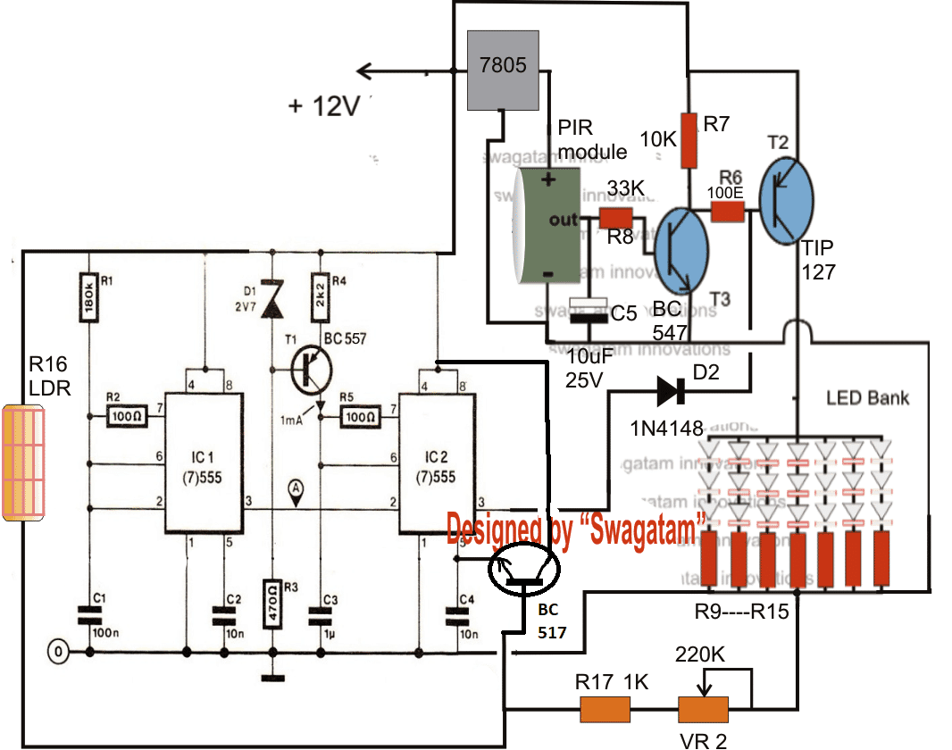
AS per the request the following energy saving intelligent light circuit consists of three separate stages, viz: the PIR sensor stage, the LED module stage, and the PWM light controller stage consisting of a couple of IC555.
So I have explained the the different stages with the following points:
The upper stage consisting of the PIR sensor module, and the associated circuit forms a standard passive infrared sensor stage.
In the presence of humans in the specified range, the sensor detects it and it's internal circuitry converts it to a potential difference so that it's fed to the base of the first NPN transistor.
The above trigger, activate both the transistors, which in turn switch ON the LEDs connected at the collector of the TIP127.
The above stage makes sure that the lights are ON only during the presence of humans in the vicinity, and are switched OFF when there's nobody around. C5 ensures the lights don't switch OFF immediately in the absence of humans rather after a few seconds of delay.
Using PWM
Next, we see two IC 555 stages which are configured as standard astable and PWM generator stages. C1 determines the frequency of the PWM, while the R1 resistor may be used for optimizing the correct response from the circuit.
The PWM output is fed to the base of TIP127 transistor. This means, when the PWM pulses consist wider pulses, keeps the transistor switched OFF for greater periods of time, and vice versa.
It implies, with wider PWMs, the LED would be weaker with their intensity, and vice versa.
We all know that the PWM output from a 555 IC (as configured in the right hand side section) depends on the voltage level applied at its control pin#5.
With higher voltages nearing the supply level makes the PWM output wider, while voltage nearing the zero mark makes the PWMs with minimum widths.
A potential divider stage made with the help of R16, R17 and VR2 accomplishes the above function such that the IC responds to the external ambient light conditions, and generates the required optimized PWMs for implementing the LED dimming functions.
R16 is actually an LDR which must receive ONLY the light from external source entering the room.
When the external light is bright, the LDR offers lower resistance thereby increasing the potential at pin#5 of the IC, This prompts the IC to generate wider PWMs making the LEDs grow dimmer.
During low ambient light levsl, the LDR offers higher resistance initiating the opposite results, that is, now the LEDs start getting brighter proportionately.
The 220K pot may be adjusted to get the best possible response from the IC 555 stage, as per individual preferences.
As per the request, the above circuit must be powered from a battery, charged from a solar charger controller circuit. I have explained many solar charger controller circuits in this blog, the LAST CIRCUIT given in the article may be used for the present application.


Questions & Answers
Hi, please type "solar changeover" in the search box given at the top of the page, you will be able to find many options from which you can select the one which suits you the best.
Hi Swagatam.
I need to combile this circuit «Solar LED Lights with Charger» with this one. I know I have to remove the LED bank from the «Solar LED Lights with Charger» but what other changes do I have to do? I need this circuit to be intirely powered up by the battery that will be charged during day and supply power during night.
Thanks.
Keep up the good projects.
Nélio Abreu
assuming these are 5mm LEDs 20mA, the resistors could be 100 ohms 1/4 each…you can add as many such strings in parallel as you may prefer depending on how much current input you may be wiling to use with the circuit
Hi,
2 more things….. what are the values of the LED bank resistors and with current configuration, how many LED's can I add to the circuit without changing transistor T2?
Thanks.
Nélio Abrue
Hi Nelio,
you'll just have to remove the 40watt LEDs as shown in the following circuit:
https://www.homemade-circuits.com/2015/03/solar-led-lights-with-charger.html
and replace with the LED bank shown in the above article, and connect the output from the linked LM338 to the supply inputs of the above PIR circuit.
Meaning the "solar LED lights with charger" output now supplies the power to the PIR/555 circuit, while the LED bank is replaced with the 40 watt LEDs.
Dear Mr. Swagatam,
Can you please explain me the detailed working of the PWM stage including both 555ic as i could understand just some of it.
Dear kkaranjia, it could be long a explanation, I'll give you brief one here:
The 555 network is a PWM generator circuit whose duty cycle could be altered by applying a proportionate magnitude of voltage at pin5 of IC2…..the LDR and the VR2 constitute a voltage divider network which become responsible for applying a varying voltage on the above pin in response to the ambient light condition which forces IC2 to generate the optimized amount of PWMs at the the base of T2 which in turn controls the LED illumination according to that proportion.
pls help me explain ur circuit well for me ..;i would like to use it as a project work ….pls help me …i am approaching the deadline for my project submission pls
It's already explained in the article….
is it safe to connect a pnp tr to the o/p of 555?? as o/p Pin 3 of 555 does not rise high enough to turn off the transistor and also 555 book prevents us to connect a pnp buffer tr to the o/p of 555. thanks
I have seen your link, it's rubbish, no IC will produce full supply voltage output, nor will it produce 100% zero output, so in that case even an NPN device won't work correctly.
We have to take external measures to counter this problem, only eliminating PNP devices cannot be the solution.
please show me the link which states this.
Hello Masena,
This circuit diagram will be quite elaborate and require a lot of time to draw, since I already have many pending requests with me, it might take sometime for your request to get published.