In this post I have explained a simple automatic PIR controlled solar garden light circuit which will switch ON the LEDs only under two conditions: when it is completely dark and when a human being is detected in the vicinity.
The above feature of the circuit ensures that the LEDs are turned ON only when it is actually required, eliminating unnecessary wastage of battery power.
Circuit Description
If you do not want to read the whole article below, then you can just watch the following video:
Parts List
- All resistors are 1/4 watt CFR unless specified.
- 220 Ohms = 1
- 1k = 1
- 10k = 2
- 330 ohms = 1
- 3 ohm 2 watt = 3
- Electrolytic capacitor 1uF/25V = 1
- Semiconductors
- Diodes 1N5402 = 2
- Diode 1N4148 = 1
- Zener Diode 5.2 v 1 watt = 1
- Transistor BD139, TIP122, BC547 = 1 each
- LEDs 1 watt, 300 mA high bright = 3
- Solar Panel, 9V 1 amp = 1
- PIR module any standard with 3 pinouts = 1
- Heatsink for the LEDs
- Battery Li-Ion 3.7 V, 2600 mAh = 1
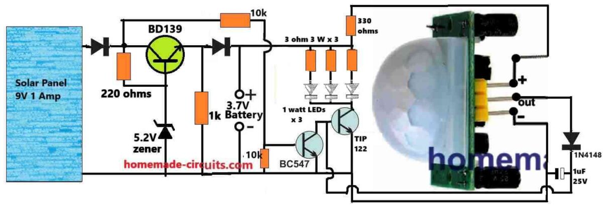
Referring to the circuit diagram, the working of the proposed PIR controlled solar garden light circuit can be understood with the following points:
During daylight when ample sunshine is available, the solar panel supplies around 9V to the BD139 regulator circuit.
The BD139 is configured as an emitter follower with its base voltage clamped to 5.2V.
Since it is an emitter follower, the emitter voltage follows the base voltage. And after deducting the 0.6V internal drop, we get around 5.2 - 0.6 = 4.6 V to develop across the emitter.
This 4.6V is further dropped by the series diode at the emitter of BD139 to create around 4V for the 3.7V Li-Ion battery.
This 4V is used for charging the Li-ion battery during daylight and when there's optimal sunshine.
Since the maximum charging voltage is restricted to 4V, which 0.2V less than the actual maximum tolerable charging limit, the Li-Ion battery charging is under safe limits.
Therefore an automatic full charge cut off is not essential for the li-ion battery in this circuit.
The above 4 V from the battery is further supplied to an LED driver stage comprising of a TIP122 driver transistor which controls 3nos of 1 watt LEDs.
However, the TIP122 conduction is completely dependent on two external factors governed by the BC547 transistor and the PIR sensor.
The BC547 transistor base is connected directly to the output of the solar panel, which means that until the solar panel drops below 0.6 V, the BC547 will remain conductive.
This also means that the TIP122 base will remains grounded until the solar panel voltage drops below 0.6 V, which can happen only when it is significantly dark outside.
Thus, the LEDs will not be able to illuminate until it is dark and the solar panel voltage has dropped below 0.6 V.
However, even when the ambient light has dropped to a point where the BC547 is turned OFF, still the base of the TIP122 will not be able to get the required biasing voltage, unless the PIR detects a human presence.
In the above situation, the TIP122 will switch ON the LEDs as soon as the PIR supplies a switching voltage to its base on detecting a human presence.
Thus, the proposed PIR controlled solar garden light circuit enhances battery power saving by making sure that the LEDs switch ON only when it is significantly dark and on detection of a human being around the garden area.
LED Specifications
The LED specifications will depend on the battery power specifications. Considering the Li-Ion battery is rated at 2600 mAh, it can comfortably handle upto 2 amp current. This implies that, the LEDs can be rated upto 2 amps.
The diagram shows three 1 watt LEDs, each rated to consume around 300 mA. Therefore, 3 LEDs will overall consume around 900 mA.
That means, there's still space for another 3 LEDs, which would then consume a total current of 1800 ma, which is within the safe discharge range of the Li-Ion battery.
Using a 6 watt LED will produce sufficient light to make the garden passages fully illuminated and bright.
This concludes our article on PIR controlled solar garden light, if you have any further questions or doubts, please feel free to comment for getting quick replies.


Questions & Answers
can you Set low brightness when there is no movement, 100% when there is movement (up to 30 seconds after movement stops)
That’s possible, just connect a calculated resistor, maybe around 100 ohms across the (+) and ((out) terminals of the PIR..
Hi – Interesting website and designs. I was looking at the PIR Controlled Solar Garden Light Circuit, as I was going to utilise something similar using a PIR.
But why are you using 1mF and 1N4148 on the output of PIR.
Could this circuit be upgraded/enhanced so the battery is a either 12v lead Acid or 3S3P Lithium.
Thanks, and I appreciate your feedback regarding the above circuit.
The diode and the capacitor at the PIR output is used to stabilize the PIR output response, although they are not strictly required…
Yes, 12V can be used, in that case the 330 ohms resistor value will need to be increased to 1k or 2.2k.
What is the 330 ohm resistor at the PIR + input for, and can that be omitted ?
No, it cannot be omitted, otherwise the PIR may malfunction. This limits the current to the PIR so that it can function correctly.
By removing all the secondary side (right side of the circuit) up to the 3.7v input (not removing the battery input) can we use it as a 3.7v battery charger
Yes, that is possible…
Dear Swagatam, regarding the PIR Controlled Solar Garden Light Circuit, there are 2 diodes which are unlabelled. Are these both 1N5402 as specified in the parts list?
Hi John,
yes, those are 1N5402 diodes.
Hello sir, can we use 12volt mini 5.2watt solar panel instead of 9volt 1amp. Is there any changes required plz guide
Hello Ghulam,
You can use 12V also in the above circuit without any changes, but 5.2 watts will produce 400 mA current which will not be sufficient for charging the 2600 mAh Li-ion battery quickly.