• Skip to main content
  • Skip to primary sidebar

Homemade Circuit Projects

Need circuit help? Post them in the comments! I've answered over 50,000!

Blog | Categories | About | Hire Me | Contact | Calculators-online
You are here: Home / Lamps and Lights / Simplest 100 Watt LED Bulb Circuit

Simplest 100 Watt LED Bulb Circuit

Last Updated on June 1, 2026 by Swagatam 163 Comments

In this article I have explained a very simple 100 watt LED bulb circuit using a few high voltage capacitors. The entire circuit could be built at a cost less than $25.

Table of Contents
  • Using Capacitive Power Supply
    • Analyzing the The Design
    • Circuit Diagram
  • Improved design with current control

I have already discussed many capacitive type of transformerless power supply circuits in this blog, however all these suffers from a couple of issues, namely lack of optimal current output, and surge inrush vulnerability.

Using Capacitive Power Supply

Upon studying capacitive power supplies deeply I could conclude a few crucial things regarding these configurations:

Capacitive power supplies are quite like solar panels which work efficiently, at their maximum power point specs when they are operated with their open circuit voltages, otherwise the current specs from these units go through heavy losses and produce highly inefficient results.

In simple words if we one desires to acquire high current outputs from a capacitive power supplies at will, the circuit will need to be operated with a load having a voltage requirement equal to the maximum output of the system.

For example with a 220V input, a capacitive power supply after rectification would produce an output of around 310V DC, so any load assigned with a 310V rating could be operated with full efficiency and at any required current level depending upon the requirement of the load.

If the above condition is satisfied, it also tackles the current inrush issue, since the load is specified at 310V, an inrush of full input voltage now has no effect on the load and the load remains safe even during sudden switch ON of the circuit.

Analyzing the The Design

In the proposed 100 watt LED bulb circuit we employ the same technique as discussed in the above sections.

As discussed, if the input is 220V the load would need to be rated at 310V.

With 1 watt 350mA standard LEDs this would mean adding 310/3.3 = 93 LEDs in series, that's close to 100nos.

A single 1uF/400V capacitor produces around 60mA current at the above specified 310V DC, therefore for achieving the required 350mA more such capacitors will need to be added in parallel, to be precise a total of 350/60 = 5 capacitors, that could also be a single 5uF/400V but should be a non-polar type.

An NTC thermistor may be added for extra safety, although it may not be critically required.

Similarly a resistor could be also included to provide extra bit of safety from fluctuating voltage conditions.

The resistance value may be approximately calculated as R = Us - VFd/I = 310-306/.35 = 10 ohm, 1 watt

For a 120V input, the above specs would simply need to be halved, that is use 47nos of LEDs instead of 93, and for the capacitor a 5uF/200V would be enough.

Circuit Diagram

Warning: Circuits I have explained below are not isolated from mains AC, and therefore are extremely dangerous to touch in the powered and open condition. You should be extremely careful while building and testing these circuits, and make sure to take the necessary safety precautions. The author cannot be held responsible for any mishap due to any negligence by the user.
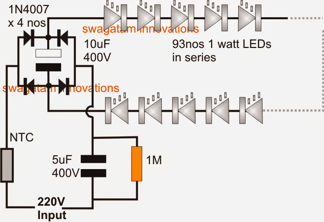
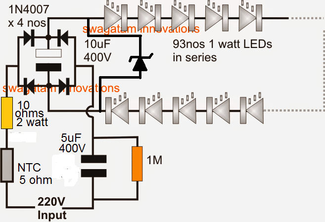
The above diagram can be additionally safeguarded from surge inrush voltages, and mains fluctuations by adding a 10 ohm limiting resistors and a zener diode, as shown below.

Here the value of zener diode should be 310V, 2 watt
Improved design with current control

The following circuit is a foolproof circuit design that will never allow the LEDs to come across a stressful condition. The mosfet and thee associated current control ensure 100% constant voltage and constant current for the connect LED bulb chain.

The number of LEDs in the chain can be adjusted as per the selected voltage, or conversely the voltage can be adjusted as per the selected number of LEDs in the chain.
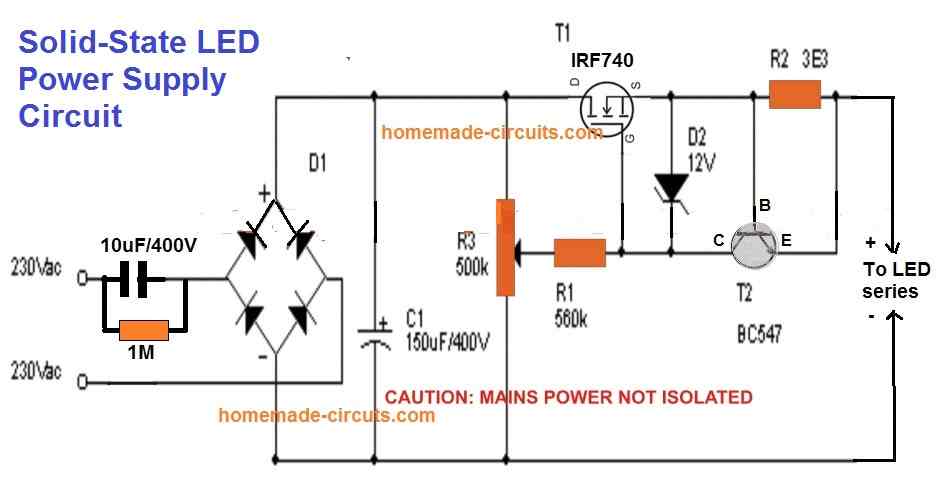
Note: Please move the capacitor C1 from the existing position to the output terminals of the circuit. Meaning, remove the C1 from across the bridge rectifier and connect it parallel to the LED string. This will drastically eliminate excess stress of the MOSFET, yet provide a filtered DC to the LEDs, increasing the overall efficiency of the design. In this case the voltage rating of C1 can be reduced to the value that's just slightly above the total forward voltage of the series LED string.

You'll also like:

  • IRLEDFloodLightCircuitDiagram252CImageInfrared (IR) LED Flood Light Circuit
  • CREE XM-L T6 LED Driver Circuit – Specifications and Practical Application
  • LED light wave generator circuitLED Light Wave Effect Generator Circuit
  • 500 V generator circuitNeon Tube Driver Circuit

Filed Under: Lamps and Lights Tagged With: 100, Bulb, LED, Simplest, Watt

About Swagatam

I am an electronics engineer and doing practical hands-on work from more than 15 years now. Building real circuits, testing them and also making PCB layouts by myself. I really love doing all these things like inventing something new, designing electronics and also helping other people like hobby guys who want to make their own cool circuits at home.

And that is the main reason why I started this website homemade-circuits.com, to share different types of circuit ideas..

If you are having any kind of doubt or question related to circuits then just write down your question in the comment box below, I am like always checking, so I guarantee I will reply you for sure!


Previous Post: « Satellite Signal Strength Meter Circuit
Next Post: Li-ion Emergency Light Circuit »

Reader Interactions

Questions & Answers

Total Posts: 163
Newest Oldest
Dangai Jonas
December 4, 2022 • 4 years ago #136895

Good evening
What would be the value of the resistor R2 for a power of 200W leds? Thanks

Reply
SwagatamAdmin
December 5, 2022 • 4 years ago #136907

Hello,
R2 = 0.7 / Maximum LED current

Reply
Daouda
December 5, 2022 • 4 years ago #136911

Merci beaucoup monsieur

Reply
Daoud
August 16, 2021 • 5 years ago #94633

Merci beaucoup Monsieur

Reply
SwagatamAdmin
August 16, 2021 • 5 years ago #94639

My pleasure!

Reply
Daoud
August 16, 2021 • 5 years ago #94619

Or at the output of my dimmer made from a triac and which I have rectified, I can put the two components connected in parallel (1M resistor and 1u / 400V capacitor). I mount several 1u / 400V capacitors in parallel until the current is 1.75A?

Reply
Daoud
August 16, 2021 • 5 years ago #94618

Hello sir, as there is no 200V zener diode in our region, I used a dimmer to vary the voltage to 200V well rectified but the leds do not shine normally. Is the current insufficient? I assumed that the current for each led is 350mA and that there are 5 lines connected in parallel which constitutes a block of 5 lines connected in parallel, each line has 24 leds connected in parallel we have in total a current of 1 , 75A. As I have 2 blocks which are connected in series. How I can increase or amplify the current so that the leds shine normally

Reply
SwagatamAdmin
August 16, 2021 • 5 years ago #94625

Hello Daoud, you will have to use a transformer based power supply which can supply 200 V 350 ma, or use an SMPS with the same rating. Capacitive method with zener diode will not produce 350 mA.

Also make sure each LED series has a limiting resistor calculated using the formula suggested in the previous email.

Reply
Daoud
August 16, 2021 • 5 years ago #94612

Merci beaucoup à l’aide que vous me donnez
Je vais donc faire comme vous l’avez dit en appliquant une tension de 200V. Merci infiniment

Reply
Daoud
August 15, 2021 • 5 years ago #94479

Good day, sir. Thank you for your help. In fact the projector of an unrecoverable switching power supply so I wanted to make another power supply. Of course I have already realized but the mosfet heats up a lot this mosfet is mounted in commutation. The led projector is 200W. How to avoid heating this transistor. This projector has 10 lines of 24 leds per line Thank you

Reply
SwagatamAdmin
August 15, 2021 • 5 years ago #94508

Hello Daoud, assuming the LED series/parallel connections are correctly calculated, the heating up issue of the transistor can be simply solved by using a higher rated transistor, whose rating must be much higher than the total power of the LEDs.

Reply
Daoud
August 15, 2021 • 5 years ago #94510

Hello Sir thank you very much for your response. I used 2 mosfets of 150W with rds 1.2 Ohms resistor, the voltage Vds 900V and the current of 9A but it still heats up you can have an idea for that please. When I limit the current with a resistance of 500 Ohms the transistor does not heat it is the resistance which heats up earlier. Can I send you the diagram please?

Reply
SwagatamAdmin
August 15, 2021 • 5 years ago #94534

You are welcome Daoud, 900 V and 1.2 ohm both don’t look compatible for your application. The VDD and ID can be at the most 1.5 times higher than the V and I specs of the series/parallel LED array. Higher VDD would also mean high RDSon which can cause the FET to heat up…..so try replacing with a MOSFET having specs only 1.5 times higher than the LED specs.

The limiting resistor must be optimally calculated, higher series resistance would unnecessarily reduce the light output of the LED.

Reply
Daoud
August 16, 2021 • 5 years ago #94576

Thank you very much Sir really I am very proud
And today I received a 180W led projector. Inside the projector we have 2 blocks of leds and each block contains 5 lines mounted in parallel each line includes 25 leds. Now the first block is mounted in series with the second block. The power supply of this projector is a switching power supply which is defective as components cannot be found on the market. I did a simple rectification then filter I obtain a voltage of 325V and I feed the projector it does not shine well. What can I do to shine well? Thank you for your help

Reply
SwagatamAdmin
August 16, 2021 • 5 years ago #94608

Thank you Daoud, the formula for the supply voltage, limiting resistors, and the current is given below: The supply DC must be slightly higher than the total forward drop of the LED series, and LED series current can be equal to the single LED current.

Limiting Resistor = supply DC – total FWD voltage of the LED series / total LED current

If the total series LED number is 24 + 24 = 48 and each LED voltage is 3.3 V. Then the total forward (FWD) LED voltage becomes 48 x 3.3 = 158 V, and any DC above this value can be applied or a maximum of 200 V DC can be applied.

Reply
Charis Young
April 21, 2021 • 5 years ago #88654

Please sir I need the schematic diagram of CTORCH LED 28W 2520Lm 250mA circuit diagram.AC input of 230-40V.
Thank you for your guided and kind response.

Reply
SwagatamAdmin
April 21, 2021 • 5 years ago #88660

Charis, I don’t have the mentioned circuit….but you can use the second circuit from the above article, and put 28nos of 1 watt LEDs. The zener diode will be 92 V.

Reply
Abdul Basit Momin
March 28, 2021 • 5 years ago #88036

Hello sir want to run 25 number of 1 watt led in series wat will be the changes in circuit

Reply
SwagatamAdmin
March 28, 2021 • 5 years ago #88051

Abdul, you can try the last circuit, adjust the voltage to 25 x 3.3 = 82 V

Reply
Ritesh Kumar Mohanty
March 30, 2018 • 8 years ago #59413

Thank you sir ,sir where i connect +ve input and -ve input ? Is the +ve can be connected in capacitor side? What is the specification of zener diode?

Reply
shelim mollik
December 27, 2020 • 6 years ago #85659

dear sir,
i made a tiktok ring light with 150 leds (1 watt 3.5 vold),27 leds were brightness and 123 leds were not bright,totally 123 leds did not work.it was without zener diod and varistor,please how to solve it?

Reply
SwagatamAdmin
December 27, 2020 • 6 years ago #85664

Hello Shelim, without seeing the schematic I cannot judge the fault, so if possible provide the complete circuit diagram.

Reply
SwagatamAdmin
March 30, 2018 • 8 years ago #59414

Ritesh, sorry actually I have updated the required diagram in the following article, please check it out

https://www.homemade-circuits.com/make-hundred-watt-led-floodlight/

Reply
Ritesh Kumar Mohanty
March 22, 2018 • 8 years ago #59258

Thanks sir, sir I can you help me by using smps ? Can you provide me that full circuit diagram and all specification of all components? Sir plz help me I am so excited about this project.

Reply
SwagatamAdmin
March 22, 2018 • 8 years ago #59259

Ritesh, please tell me the total number LEDs, and the wattage of the LEDs you want to use for the project.

Reply
Ritesh Kumar Mohanty
March 29, 2018 • 8 years ago #59390

Thanks Sir,Sir I want to do a 100 watt LED lamp with 1watt LEDs .sir please give me proper circuit diagram and provide me full specification of all components used in this project. Sir plz help me kindly I am so excited to perform this project. Plz sir

Reply
SwagatamAdmin
March 29, 2018 • 8 years ago #59398

Ritesh, I have updated the diagram above…you can check it out

Reply
Ritesh Kumar Mohanty
March 22, 2018 • 8 years ago #59251

Thanks sir, Sir I am very excited to do this project sir can you help me? Can you provide the actual practical circuit diagram of this project , with all components and all’s specification. Sir plz can you send me with full description?

Reply
SwagatamAdmin
March 22, 2018 • 8 years ago #59253

Ritesh, I have undated the diagram, but please do it at your own risk, because mains current is always dangerous and you cannot predict it 100%.

If you want 100% guaranteed results then it is always better to go for an SMPS based power supply or a transformer based power supply.

Reply
Ritesh Kumar Mohanty
March 21, 2018 • 8 years ago #59237

Sir,As shown in circuit diagram can I connect the zener diode in parallel with 10uf 400v capacitor ? What’s the specification of zener diode ?where can I connect the heat sink and what’s the specification of heatsink

Reply
SwagatamAdmin
March 22, 2018 • 8 years ago #59247

yes you must connect it in parallel to the 10uF/400V cap. The zener value should be equal to the total forward drop of the LEDs in series. Heatsink will need to be determined through practical experimentation

Reply
Ritesh Kumar Mohanty
March 21, 2018 • 8 years ago #59228

Hello Sir, thanks for your support , Sir can I know where the ntc is connected in +ve of input or in -ve of input ?and what is the specification of zener diode? and where I can use to the zener diode?sir plz kindly respond me.plz help me out

Reply
SwagatamAdmin
March 21, 2018 • 8 years ago #59231

Ritesh, NTC can be connected anywhere in the line, either in the positive line or the negative.
zener diode can be connected parallel to the filter capacitor.
but make sure to connect a small value resistor, may be a 50 ohm 2 watt in series with the NTC.

Reply
Nazim
March 18, 2018 • 8 years ago #59159

Thanks Sir

Reply
Nazim
March 13, 2018 • 8 years ago #59061

Dear.. how are you sir i hope your healthy n fir ..
can can you provide me the circuit diagram of *manual heat sealing machine*

Reply
SwagatamAdmin
March 13, 2018 • 8 years ago #59064

Nazim, the procedures involved are purely mechanical so I won’t be able to help you with it, since my expertise is lies only with electronic circuits

Reply
Nazim
October 28, 2017 • 9 years ago #55322

Dear Swagatam sir
Simplest 100 Watt LED Bulb Circuit.

1Watt LED
Forward current: 350mA
Forward Voltage: 3.2V~3.4V in average (3.3V*93Leds= 306.9V),
In india we are getting Indian power supply 240V 50Hz then how this circuit working.

My dought is input voltage is lower around 220V~250V and output Voltage is Higher (3.3V*93Led)=306.9V… how ita working sir

Reply
SwagatamAdmin
October 28, 2017 • 9 years ago #55325

Hello Nazim, the 220V is the average value of the AC, alo called the RMS, the peak value of this 220V AC is always around 310V.

when we rectify this 220V with a bridge and filter capacitor, the 310V is produced and sustained at the output by these components, therefore the output that we get is 310V DC instead of 220V AC.

Reply
SwagatamAdmin
October 28, 2017 • 9 years ago #55326

I hope you have a basic digital meter with you to check the voltages, which is a must for any electronic hobbyist.

Reply
Nazim
October 24, 2017 • 9 years ago #55111

I think 5uf is sufficient for led if the brightness is not getting sufficient then it may b led fault or any other fault in my circuit sir ? Im i correct sir

Im not get 310v 2watt zener diode in my local market so i let it and only 5uf +1uf again add totall 6uf then the above said situation happen.

Did zener diode controls the volts or Ampere sir?

Reply
SwagatamAdmin
October 24, 2017 • 9 years ago #55131

did you connect a large heatsink with the LEDs? at 300mA the LEDs can get immensely hot and will blow within a minute.

without a zener the LEDs can burn with a slightest mains fluctuation.

zener will control voltage and will prevent rise in abnormal current consumption.

Reply
Nazim
October 24, 2017 • 9 years ago #55110

Dear Swagatam sir,
If i want to run 1watt 350mA led on 12-0-12 , 5Ampere transformer.
Q1 :- How can i run 1watt 350ma leds?
Q2:- What changes i have to done in above 100watt bulb circuit?
Q3:-how many leds can i operates with 12-0-12 5ampere transformer with out any problem to enter set?

In the previous 93led circuit i have add one 1uf/400v non polar capacitor then i give supply after some time 5to10mints leds become slowly dim by dim i think “1uf producing 70mA (70*5=350mA)

Reply
SwagatamAdmin
October 24, 2017 • 9 years ago #55130

Dear Nazim,

connect then as shown in the last diagram of this article

https://www.homemade-circuits.com/make-this-1000-watt-led-flood-light/

each string will consume .3 x (3.3 x 6) = 6 watts

your transformer supply is 24 x 5 = 120 watts

so you can connect 120/6 = 20 such parallel strings

Reply
Dipan shah
May 16, 2019 • 7 years ago #67052

Hello sir,
I have made this tranformerless circuit using MB10S bridge rectifier. I have used 250v 1.1uf non polorised capacitor and 250v 10uf polorised capacitor with 470 ohm 1 watt resistor at output with series of 52 leds string. But at output i am getting only 37mA. When i need 60mA. When i tried using 250v 2.2uf non polorised capacitor it became so hot. And other thing is i have some size ristrictions for this driver so if i use 400v non polorised capacitor then it will be so big and will not fit in. So can you plesse give me dome solution over this problem?
Thank you.

Reply
SwagatamAdmin
May 16, 2019 • 7 years ago #67066

Dipan, to get 60mA you will need a 2uF/400V capacitor. 400V is required for guaranteed safety to the capacitor so it is a must. For smaller size you can use 250V but that will not ensure a 100% safety for the capacitor.

Reply
Nazim
October 20, 2017 • 9 years ago #54989

Dear Swagatam sir

(Did i need to place between “6uf/400v ….(310b 2watt zener diode ?)…… 10uf/400v) right sir

Reply
Nazim
October 20, 2017 • 9 years ago #54988

Dear Swagatam sir
Simplest 100 Watt LED Bulb Circuit.

(Did i need to place between “6uf/400v ….(310b 2watt zener diode ?)…… 10uf/400v) right sir

Reply
SwagatamAdmin
October 20, 2017 • 9 years ago #54990

Dear Nazim, yes connect ii across the same points where 10uF/400V capacitor leads are connected, anode of zener to minus of capacitor, cathode to plus pin of capacitor.

Reply
Nazim
October 20, 2017 • 9 years ago #54986

Dear Swagatam sir
Simplest 100 Watt LED Bulb Circuit.

310V 2 watt zener
in the above design circuit where i have to place the zener diode

waiting for your great replay sir thanks a lot sir. thank you very much sir

Reply
SwagatamAdmin
October 20, 2017 • 9 years ago #54987

you can connect its anode with the negative line (-310V line) and cathode with the positive line (+310V line)

Reply
Nazim
October 20, 2017 • 9 years ago #54979

Dear Swagatam sir.
Simplest 100 Watt LED Bulb Circuit,

Can i get sufficient brightness if i add below two parts to circuit
part 1:- 1uF 400V Non-Polar Metallized Film Capacitor
part2:- 310V 2 watt zener (it shoud be add on 1n4007 diode brige im i correct sit and i dnt know how to connect the position )

Reply
SwagatamAdmin
October 20, 2017 • 9 years ago #54984

Dear Nazim, obviously if the each LED gets 3.3V at 300mA then all the LeDs will illuminate at optimal brightness.

dividing 310V with 93 LEDs gives 3.33 which is the right voltage value for each of the LEDs.

and if a 6uF cap is used it will provide the required 300mA to the whole string. if it doesn’t then the problem could be somewhere in your parts or the connections.

310V zener is only to make sure the max voltage to the LeDs does not go above 310V, which can otherwise damage the whole string.

however if the supply voltage drops below 300V DC (210V AC) then the LEDs will become dimmer…at 200V (145V AC) the LEDs will almost off.

Reply
Nazim
October 19, 2017 • 9 years ago #54953

Dear Swagatam sir
Simplest 100 Watt LED Bulb Circuit

1uF/400V capacitor produces around 60mA (as i read in your blog if we add 1 or 2 more capacitors it will produce above 350mA im i correct sir)

A single 1uF/400V capacitor produces around 60mA current at the above specified 310V DC, therefore for achieving the required 350mA more such capacitors will need to be added in parallel, to be precise a total of 350/60 = 5 capacitors, that could also be a single 5uF/400V but should be a non-polar type.

Reply
SwagatamAdmin
October 20, 2017 • 9 years ago #54962

Hello Nazim, yes you can add a couple of more 1uF capacitor to increase current for the LEDs, but this can make the Leds vulnerable to slightest voltage fluctuations and burn them. 1uF will practically give around 50mA…not 60mA which may be true only as per the formula.
the capacitor should be a non-polar.

Reply
Nazim
October 19, 2017 • 9 years ago #54952

Dear Swagatam sir
Simplest 100 Watt LED Bulb Circuit

If i add “1uf 400v” two more capacitors in my old circuit can get sufficient brightness sir

Reply
Nazim
October 19, 2017 • 9 years ago #54938

Dear Swagatam sir
Simplest 100 Watt LED Bulb Circuit
Thanks you very much for give each and every part information finally i have successfully turn on led bulb with my partner jatin thanks a lot “SWAGATAM SIR AND JATIN” but a led not giving sufficient brightness can…

Can you give information about “Capacitor Based LED Tubelight Circuit Using 1 Watt LEDs” https://www.homemade-circuits.com/2014/07/capacitor-based-led-tubelight-circuit.html

Is tube light me use kre hue parts ki information dejiye na identify karne k lye plz
Thanks a lot sir

Reply
SwagatamAdmin
October 19, 2017 • 9 years ago #54943

Thank you dear Nazim, I am glad you could make it successfully….the illumination can be increased by reducing the number of LEDs in series…if you use 93 LEDs, the brightness will be maximum..also the 5uF capacitor will give only 250mA current which is not full current for the 1 watt LEDs…so you can add one more capacitor in parallel to make it 300mA, but this will make the LED more vulnerable to surge currents…

the details of the other tubelight is discussed in the comment section, please check it in the comment discussion. and also it is given in the last PCB design

Reply
Nazim
October 15, 2017 • 9 years ago #54845

Dear Swagatam sir
Simplest 100 Watt LED Bulb Circuit
below the four parts images from url once see and say me there are correct image of parts sir,

1.10uf 400v (1 pieces ) ( Image url )
if i don’t get 10u 400v can i take 10u 450v

2. 1uf 400v (5 pieces should be connected in parallel series )(Image url )

3. NTC Details (Image url )
(if ntc not available in local dealer can i leave it sir)

4. 1watt 350mA led (image url )

waiting for your great replay sir thanks a lot sir for proving me each and every information with out hesitating . thank you very much sir

Reply
SwagatamAdmin
October 16, 2017 • 9 years ago #54851

Hi Nazim, all those examples are correct, you can go ahead with them.

the LEDs will require a large heatsink, so please do not forget to mount them on a hetasink.

Reply
Nazim
October 14, 2017 • 9 years ago #54832

Dear Swagatam sir
Simplest 100 Watt LED Bulb Circuit
Went to local spare parts dealers and show circuit diagram did not understand . All they asked me image or images of parts r types of capacitors and Resistor 1M Watt? And NTC details so i aked you images sir plz help me to success in this making bulp
1.10uf 400v {image or capacitor type}
2. 5uf 400v {image or capacitor type}
3.1M (Resistor Ohms and watt)
4. NTC Details {image or details }

Local dealers give me perfect by seeing circuit diagram 1watt led and diode 1n4004 this two item only i have got the above mentioned 4parts asking more details

Can this bulp run on indian voltage India 240v 50Hz im waiting for your great reply sir thanks a lot sir for providing me a lot of information. Thank you thank a lot

Reply
SwagatamAdmin
October 15, 2017 • 9 years ago #54835

Nazim, to make the 100 watt bulb run correctly you will have to make it exactly as suggested in the diagram, any other method will burn your LEDs, yes it is intended for 250V input

1N4004 will not work…you must use 1N4007 only.

If you don’t get the NTC then you can use an scr based circuit as shown below:

https://www.homemade-circuits.com/2016/07/scr-shunt-for-protecting-capacitive-led.html

just replace the 12V zener with a 300V zener, and replace the 100uF/25V with 10Uf/400V

Reply
Nazim
October 14, 2017 • 9 years ago #54825

Simplest 100 Watt LED Bulb Circuit.

dont mind sir asking too much because i am not a (Electronic & electrical engineering ) Background student im a commerce student ..after seeing your website i plan to work in this circuit design .
i have bought 1w 350mA leds with heat sink plate
i need below parts images to work in this

i need some images of parts
1. 10uf 400v {image needed}
2. 5uf 400v {image needed}
3.1M (Resistor Ohms and watt)
4. NTC Details {image needed}
can you provide me sir please sir
Email: [email protected]

Reply
SwagatamAdmin
October 15, 2017 • 9 years ago #54834

Nazim, If I show you the image then you may go strictly as per the image, which can make things more complex so it’s better that you only take the following parts list and show it to the shopkeeper, he will be able to guide you and provide you the materials:

1) 10uF/400V electrolytic capacitor – 1no
2) 5uF/400V can be built by putting 5nos of 1uF/400V PPC capacitors in parallel, this capacitor is normally labelled as 105/400V PPC or MKT.
3) 1M 1/4 watt CFR, – 1 no
4) NTC = 11mm, 5 ohm type 1no, or any suitable will do.

Reply
Nazim
October 13, 2017 • 9 years ago #54779

Hello sir i need a circuit diagram with items details of 96leds {1watt 350mA} could you please help

Reply
SwagatamAdmin
October 13, 2017 • 9 years ago #54784

Nazim, you can use the same design which is explained in the above article.

Reply
Mircea Raileanu
January 3, 2017 • 10 years ago #47775

hi sir, can i use this circuit to power up a pair of pc speaker thank you

Reply
SwagatamAdmin
January 4, 2017 • 10 years ago #47788

No, you must use an SMPS, the above is not recommended.

Reply
KENNY HO
October 22, 2016 • 10 years ago #45775

HI SIR, CAN YOU PLEASE ADVISE ME ON YOUR CIRCUIT?
IM USING 17X1W LED IN SERIES
INPUT 230V AC, I CANT GET THERMISTOR AS YOU SUGEST
CAN I USING THIS CIRCUIT? ANY COMPONENT TO CHANGE??

Reply
SwagatamAdmin
November 9, 2016 • 10 years ago #46312

Hi John, please specify the wattage of the bulb.

Reply
John Philip Ivan
November 9, 2016 • 10 years ago #46304

Hi sir. Can you gibe a circuit for using drop capacitor to convert my 110v 60hz smart bulbs to 220v 60hz ? what values for Capacitor and Resistor do i need. Regards.

Reply
SwagatamAdmin
October 22, 2016 • 10 years ago #45776

Kenny, you can try the following concept instead

https://www.homemade-circuits.com/2016/07/scr-shunt-for-protecting-capacitive-led.html

just replace the zener with a 56V 1 watt zener diode for 17 LEDs and replace the 1K resistors with 10K.

Reply
Unknown
July 6, 2016 • 10 years ago #42362

I assembled the above circuit with 83 1w leds and 2 x 225k capacitors and used one inductor coil also in the circuit. It is working superb. Many Thanks for your help. VG KRISHNA from Hyderabad.

Reply
VG KRISHNA
July 9, 2016 • 10 years ago #42431

Thank you sir, I will add NTC also.

Reply
SwagatamAdmin
July 6, 2016 • 10 years ago #42363

I am glad it's serving the purpose, but make sure to add an NTC also to provide additional safety to the LEDs

Reply
A Prakash Rao
April 2, 2016 • 10 years ago #40239

Sir, please tell the value of the thermistor to be used in the 100w led circuit.

Reply
SwagatamAdmin
April 3, 2016 • 10 years ago #40249

Prakash, you can use a 2 ohm NTC

Reply
satheesh k Nalluswamy
January 24, 2016 • 11 years ago #37983

Shopkeeper recommended this to me. NTC 10S100L would use this instead of the NTC 5D-11Tell us your advice
Waiting for your replay thank you sir

Reply
SwagatamAdmin
January 24, 2016 • 11 years ago #37993

It should work, it's a 10 ohm NTC a little higher in resistance though…. you can try it.

Reply
satheesh k Nalluswamy
January 23, 2016 • 11 years ago #37981

Sir Namaste my sincere thanks for your advice.

There is another suspect.
Can I use this NTC 10S100L instead of that you have to NTC 5D-11 . Would it be much safer if I use this?
Can I use it to circuits in your blog?

Reply
satheesh k Nalluswamy
January 22, 2016 • 11 years ago #37939

sir,
Is it possible to 8mm 0.75 Watt Clear White led

Reply
SwagatamAdmin
January 22, 2016 • 11 years ago #37958

It is possible, just reduce the input cap to around 4uF/400V

Reply
satheesh k Nalluswamy
January 22, 2016 • 11 years ago #37938

Sir,
In fact am receiving very greatly help from your blog. And most significant article be present you converse with each person who needs proper supervision. I’m so beholden of this blog and you

Reply
SwagatamAdmin
January 22, 2016 • 11 years ago #37957

Thanks Satheesh!! It's my pleasure ….

Reply
satheesh k Nalluswamy
January 19, 2016 • 11 years ago #37811

Sir,
Good day to you can i use this if I have to do 25 1WATT LED. If so what changes need to?

I learned a lot in your blog. Five circuits were successfully accomplished by using your blog. Thank you sir

Reply
SwagatamAdmin
January 19, 2016 • 11 years ago #37827

Thanks Satheesh, the number of LEDs should be around 80 to 100….25nos could be risky because its total forward voltage drop may be much lower than the AC level.

If you intend to have a 25 watt output in that case you can try using lower wattage LEDs so that you can increase their quantity to around 80 to 90 of them.

Reply
Shekhar Jaiswal
December 30, 2015 • 11 years ago #37173

Hello sir

I wish to create a light of 3w 30 white leds with ac 220 supply. Ive bought the leds & heatsink( 30 led in series ). Please guide me with the circuit diagram with capacitor, resistors etc & how to go about. Please..i

Reply
SwagatamAdmin
January 22, 2016 • 11 years ago #37928

make 5 strings having 6 LEDs in series with a 7 ohm/3 watt resistor on each series.

connect their common (+)/(-) terminals with the SMPS.

if you use a sufficiently large heatsink then you could eliminate the use of a current controller.

otherwise you may prefer to include the following circuit in the middle of SMPS and the LED

https://www.homemade-circuits.com/2013/06/universal-high-watt-led-current-limiter.html

Reply
Shekhar Jaiswal
January 21, 2016 • 11 years ago #37916

Description
1.Power: 3W
2.Work voltage:DC3.0-3.4V
3.Current :700mA
4. efficiency:100-120LM/W
5. Lumens: 180-200lm
6.View angle: 120degree

Reply
SwagatamAdmin
January 21, 2016 • 11 years ago #37894

please tell me the LED voltage specification.

Reply
Shekhar Jaiswal
January 20, 2016 • 11 years ago #37883

Sir I purchased 24v 5amp smps for driving 3w 30pcs led. Waiting your reply

Reply
Shekhar Jaiswal
January 20, 2016 • 11 years ago #37870

Sir I purchased a 24v 4a smps what in next process.

Reply
SwagatamAdmin
December 31, 2015 • 11 years ago #37202

sorry i could not understand, do you mean the LEDs are clamped with this heatsink from the manufacturer??

Reply
Shekhar Jaiswal
December 31, 2015 • 11 years ago #37196

The LED heatsink sized (6"x8") which I have is in a series of 30 and it cannot be modified. Please let me know how do I use this?

Reply
SwagatamAdmin
December 30, 2015 • 11 years ago #37185

Hello Shekhar, your wattage requirement is quite big, it's 3 x 30 = 90 watts, so I would suggest an SMPS circuit for driving it for a reliable and a long lasting performance.

So first buy a 12V/ 8 amps SMPS or a 24V 4 amp smps unit….then I'll tell you how to proceed.

Reply
GOPAL KUMAR
December 26, 2015 • 11 years ago #37017

i want to light 18 ( or 20 ) led smd bulbs (10 watt each) in series with direct mains supply (220 volt ac) using rectifier and some resistance.
each led is rated at 12volt, 1 amp.
i don't want to use input capacitor (to make it simple).
i can increase led numbers to reduce heat production.
can this arrangement run using half wave rectifier ??. if we use half wave rectifier then what is the risk, i have 6A4 MIC RECTIFIER rated at 420 volt 6 amp.

Reply
SwagatamAdmin
January 20, 2016 • 11 years ago #37864

fan capacitors can be too bulky, a 10uF/4000V electrolytic cap will be much compact

Reply
GOPAL KUMAR
January 20, 2016 • 11 years ago #37851

can we use four 2.5uF capacitors (used in ceiling fan) instead of 10uF capacitor.

Reply
SwagatamAdmin
December 26, 2015 • 11 years ago #37021

the input capacitor is compulsory, otherwise your LEDs could get damaged instantly anytime. dividing 230 by 12 gives 19 so probably you could use 20nos of 10 watt LEDs in series.

The input capacitor could be rated at 10uF/400V (non-polar), and the set up should be exactly as shown in the above article.

half waver rectification will lower the illumination of the LEDs…but there's no risk in it.

Reply
View Older Comments

Need Help? Please Leave a Comment! We value your input—Kindly keep it relevant to the above topic! Cancel reply

Your email address will not be published. Required fields are marked *

Primary Sidebar


Categories

  • Arduino Projects (95)
  • Audio and Amplifier Projects (134)
  • Automation Projects (18)
  • Automobile Electronics (104)
  • Battery Charger Circuits (90)
  • Datasheets and Components (109)
  • Electronics Theory (150)
  • Energy from Magnets and Earth (41)
  • Games and Sports Projects (11)
  • Grid and 3-Phase (20)
  • Health related Projects (27)
  • Home Electrical Circuits (13)
  • Indicator Circuits (16)
  • Inverter Circuits (98)
  • Lamps and Lights (161)
  • Meters and Testers (72)
  • Mini Projects (28)
  • Motor Controller (68)
  • Oscillator Circuits (30)
  • Pets and Pests (15)
  • Power Supply Circuits (91)
  • Remote Control Circuits (50)
  • Security and Alarm (65)
  • Sensors and Detectors (107)
  • SMPS and Converters (46)
  • Solar Controller Circuits (62)
  • Temperature Controllers (44)
  • Timer and Delay Relay (50)
  • Voltage Control and Protection (44)
  • Water Controller (37)
  • Wireless Circuits (31)


Circuit Simulator

circuit simulator image


Subscribe to get New Circuits in your Email


Other Links

  • Privacy Policy
  • Cookie Policy
  • Disclaimer
  • Copyright
  • Videos
  • Sitemap

People also Search

555 Circuits | 741 Circuits | LM324 Circuits | LM338 Circuits | 4017 Circuits | Ultrasonic Projects | SMPS Projects | Christmas Projects | MOSFETs | Radio Circuits | Laser Circuits | PIR Projects |


Recent Comments

  • Swagatam on Simple Delay Timer Circuits Explained
  • Maddy on Simple Delay Timer Circuits Explained
  • Swagatam on HX710B Air Pressure Sensor Datasheet, How to Connect
  • Swagatam on Simplest One Transistor Regulated Power Supply Circuit
  • Luciano Orozco on HX710B Air Pressure Sensor Datasheet, How to Connect

Social Profiles

  • Twitter
  • YouTube
  • Instagram
  • Pinterest
  • My Facebook-Page
  • Stack Exchange
  • Linkedin

Calculators

  • ZVS Induction Heater + Tank Calculator Tool
  • Zener Diode Calculator
  • Wire Current and Thickness Calculator (Ampacity Calculator)
  • Voltage Divider Calculator
  • Transistor Base Resistor Calculator
  • Transistor Astable Multivibrator Calculator
  • TL431 Calculator
  • Solar Panel, Inverter, Battery Calculator
  • Ferrite Core Air Gap Calculator Tool
  • Parallel MOSFET Calculator Tool: How to Connect MOSFETs in Parallel Safely
  • LC Resonance Calculator for EV Battery Charger Circuits
  • LED String Series Resistor Calculator
  • Calculator to Design a High Power 3kW PFC (Power Factor Correction) Circuit
  • Passive Power Factor Correction (PFC) Calculator
  • LM567 IC Calculator Tool
  • SMPS Flyback Boost Converter Calculator
  • Shunt Resistor Calculator for Ammeters
  • SCR and Triac Gate Resistor Calculator
  • Battery Back up Time Calculator
  • Boost Converter Calculator (Non-Isolated)
  • Bootstrap Capacitor Calculator
  • Buck Converter Calculator
  • Buck-Boost Converter Calculator
  • Capacitance Reactance Calculator
  • DCM Flyback Transformer & Wire Gauge Wire Size Calculator Tool
  • Filter Capacitor Calculator
  • IC 4047 Calculator (Frequency and PWM)
  • IC 4060 Calculator
  • IC 555 Astable Calculator
  • IC 555 Monostable Calculator
  • IC SG3525, SG3524 Calculator
  • Inductance Calculator
  • Induction Heater Inductor and Resonant Frequency Calculator
  • Induction Heater Work Coil Calculator
  • Inverter LC Filter Calculator
  • LC Resonance Calculator
  • LED Current Calculator
  • LM317, LM338, LM396 Calculator
  • NAND/NOT Gate RC Values Calculator
  • NOT, NAND Gate Frequency Calculator
  • Notch Filter Calculator Tool
  • Ohm’s Law Calculator
  • Phase Angle Phase Shift Calculator
  • Power Factor (PF) Calculator
  • RC Filter Calculator
  • Reactance Calculator
  • Sine Table Calculator for SPWM Arduino Code
  • Small Signal Transistor(BJT) and Diode Quick Datasheet
  • SMPS Calculator for Toroidal Ferrite Transformers
  • SMPS Flyback Transformer Calculator – Design by Target Duty Cycle
  • TL431 Calculator

© 2026 · Swagatam Innovations