A very simple low battery cut-off and overload protection circuit has been explained here.
The figure shows a very simple circuit set up which performs the function of an overload sensor and also as an under voltage detector.
In both the cases the circuit trips the relay for protecting the output under the above conditions.
How it Works
Transistor T1 is wired as a current sensor, where the resistor R1 forms the current to voltage converter.
The battery voltage has to pass through R1 before reaching the load at the output and therefore the current passing through it is proportionately transformed into voltage across it.
This voltage when crosses the 0.6V mark, triggers T1 into conduction.
The conduction of T1 grounds the base of T2 which gets immediately switched Off. The relay is also consequently switched OFF and so is the load.
T1 thus takes care of the over load and short circuit conditions.
Transistor T2 has been introduced for responding to T1's actions and also for detecting low voltage conditions.
When the battery voltage falls beyond a certain low voltage threshold, the base current of T2 becomes sufficiently low such that it's no longer able to hold the relay into conduction and switches it OFF and also the load.
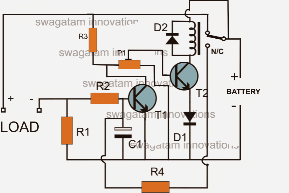
The"LOAD" terminals in the above diagram is supposed to be connected with the inverter +/- supply terminals.
This implies that the battery current from the right side has to pass through R1 before reaching the inverter, enabling the sensing circuit around R1 to sense a possible over current or overload situation.
CORRECTION:
The above shown circuit will not initiate unless the relay is actuated manually through a push switch as shown below:
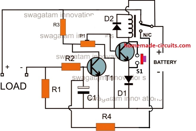
Parts List
- R1 = 0.6/Trip Current
- R2 = 100 Ohms,
- R3 =10k
- R4 = 100K,
- P1 = 10K PRESET
- C1 = 100uF/25V
- T1, T2 = BC547,
- Diodes = 1N4148
- Relay = As per the specs of the requirement.
Formulas and Calculations
Low Battery Cut-off Threshold
The low battery sensing is handled by R3 and P1 which forms a potential divider to set the base voltage of the relay driver transistor (T2). When the battery voltage drops below a set threshold the voltage at the base of T2 falls below Vbe (0.6V–0.7V) turning OFF the relay and disconnecting the load.
Formula for Threshold Voltage:
Vth = Vbat * (P1 / (P1 + R3))
- Where:
- Vth = Base threshold voltage (0.6V–0.7V)
- Vbat = Battery voltage
- P1 = Adjustable potentiometer resistance
- R3 = Fixed resistor
To calculate the battery voltage cut-off level:
Rearrange for Vbat:
Vbat = Vth * (P1 + R3) / P1
Overload/Overcurrent Sensing
Overcurrent protection is implemented using R1 which is placed between the base and emitter of transistor T1.
As the load current increases, the voltage drop across R1 rises. When the voltage across R1 reaches the Vbe of T1 (typically 0.6V–0.7V) T1 starts conducting and shunts the base current of T2 turning it OFF.
Formula for Overcurrent Trip Current:
Itrip = Vbe / R1
- Where:
- Itrip = Overcurrent trip current
- Vbe = Base-emitter threshold voltage of T1 (0.6V–0.7V)
- R1 = Resistor sensing the overcurrent
Base Current Limiting Resistor (R2)
Resistor R2 (optional) limits the base current for T1 to prevent excessive current through its base-emitter junction.
Formula for Base Resistor (if used):
R2 = (Vbat - Vbe) / Ib
- Where:
- Ib = Required base current for T1
- Vbat = Battery voltage
- Vbe = Base-emitter voltage of T1
For small signal transistors (e.g., BC547) Ib can be estimated as Iload / hFE where hFE is the DC current gain.
Inverter Overload Cut-OFF using Opamp
In the above paragraphs I have explained a very simple concept of inverter overload cut-off using only transistors.
However a cut off system using only transistors cannot be very accurate and sharp.
In order to get a precision inverter overload and short circuit cut off circuit the use of an opamp based design becomes imperative.
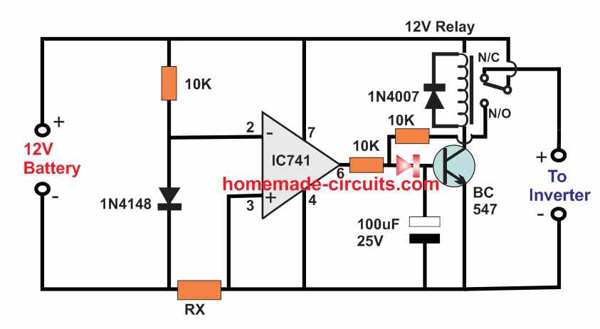
The following diagram shows a simple battery overload controller circuit using a single opamp 741 and a relay driver stage.
How it Works
The opamp is configured as a simple comparator circuit. he inverting input of the opamp is clamped at a fixed 0.6 V using a 1N4148 diode.
The non-inverting input of the op amp is connected with the negative line of the circuit through a over-current sensor resistor Rx.
Due to inverter overload or short circuit or over current conditions, a voltage drop develops across the resistor Rx which can exceed the 0.6V as per the calculated value of the RX, and cause the non-inverting input of the opamp potential to go higher then its inverter 0.6V potential.
This causes the op amp output to turn high activating the transistors and tripping the relay.
When power is first switched ON, and assuming the inverter is working normally without an overload, the voltage developed across RX is minimal, which keeps the pin3 potential of the opamp the opamp lower than the pin2 potential.
This allows the output of the opamp to be low ensuring that the transistor is switched OFF, and relay contacts stays at the N/C point.
Due to this the 12V is able to reach the inverter and operate it normally.
However, as soon as an overload or over current happens at the inverter side, a large amount of current passes through the RX resistor, causing a voltage drop to develop across pin3 of the IC.
When this voltage drop exceeds the 0.6V reference level of the pin2 of the IC, the output of the op amp goes high, causing the transistor to switch ON and trigger the relay.
The relay contacts now shift from N/C to N/O switching of power to the inverter and thereby averting the short circuit or overload conditions.
The N/O contact can be seen attached with the base of the relay driver transistor, which ensures that as soon as the an overload is detected the relay contact quickly latches the transistor, switching the power permanently off for the inverter.
The power can be restored only by disconnecting the 12 V battery input, but before that it must be ensured that the short circuit or the over load condition is appropriately removed from the inverter side.
Formulas and Calculations
Key Parameters
- RX: Current sensing resistor (ohms)
- Vref: Reference voltage at the inverting input (-) of IC741
- Itrip: Overcurrent trip current (amperes)
- Vdrop: Voltage drop across RX at trip current
Formulas
Voltage Drop Across RX:
Vdrop = Itrip * RX
- Where:
- Itrip = Overcurrent trip point (A)
- RX = Current sensing resistor (ohms)
Reference Voltage (Vref):
The voltage at the non-inverting input (+) of IC741 is set using a resistor divider or Zener diode (if used). For proper cutoff:
Vref ≈ Vdrop
Choosing RX (Sensing Resistor):
To calculate the value of RX for a given trip current:
RX = Vref / Itrip
- Where:
- Vref = Reference voltage (V)
- Itrip = Desired trip current (A)
Power Dissipation in RX:
The sensing resistor RX must handle the power dissipated during operation.
We will Use:
P = Itrip2 * RX
- Where:
- P = Power dissipation in RX (W)
Choose RX with a power rating higher than P for safe operation.
Example Calculation
Let’s assume:
Itrip = 10A (trip current)
Vref = 0.7V (reference voltage determined by the op-amp threshold)
Step 1: Calculate RX
RX = Vref / Itrip = 0.7 / 10 = 0.07 ohms
Step 2: Power Dissipation in RX
P = Itrip2 * RX = 102 * 0.07 = 7W
Choose a 0.07-ohm 10W resistor for RX to ensure safe operation.


Questions & Answers
No this circuit cannot be used in any manner for feeding a 3525 input, because the IC requires definite logic level which cannot be achieved from a transistor, you will have to incorporate a 741 IC for it.
New question about this: Could two of these circuits be hooked up to the same relay?
I have an RV with two sets of batteries: house and chassis. When the engine is running (the chassis battery is over 13V), I want to connect the two sets of batteries. When the house is plugged in (house battery over 13V), connect the two sets of batteries.
Also, if the voltage of either side goes over 16V, disconnect them (that part may be harder, and not an original requirement, it just occurred to me).
I was hoping to build two of these circuits, one hooked up to the chassis battery and the other hooked up to the house battery, and have a single relay connect the two batteries. I want to limit the current that crosses the relay to about 30amps (the max output of the house battery charger, as the engine alternator can put out 190amps).
I'm currently hunting for a relay that will strongly move to open when the coil isn't energized, as I don't want bumps in the road to accidentally flip the relay to the connected state.
Yes that would be possible, you just have to make the collectors of T2 common from the two circuits, and join with the relay coil.
For 30 amps you would need a powerful relay which would obviously have a tough electromagnetic connection, so hopefully it won't be rattled by the "bumps"
T2s will need to be appropriately dimensioned as per the relay coil ratings.
Hi, thank you for your great cutoff circuit. I suppose the cutoff voltage is changing by temperature quite large range in your circuit. A base-emitter voltage of the bipolar transistor has a temperature coefficient at least -2mV/C. That is not a problem because a battery to be charged only in specified temperature range.
you are right, thanks!
Make R3 = 22k, and R2 = 1k, that's all, other components will remain as is except the relay which should be 24V rated.
I easily get confused, after I drew the schematic diagram. My questions are;
1st:There are 3 connections for R3 preset, the 3rd will not be connected, right?
2nd: Where will the negative polarity of the battery be connected?
3rd: T2 base is connected to the 1K, while the other two terminals go to the positive and the ground respectively. Is the emitter the ground?
Could help me redraw the schematic?
And for just overload cut-off circuit, what would I need in a circuit and what would the schematic look like?
1) In the above updated diagram R3 is a fixed resistor P1 is the preset, yes, any two terminals of the preset can be selected, the center lead being the mandatory one.
2)the line which joins R1, T1 emiter, C1 negative and D1 cathode is the negative line.
3) please refer to the above diagram, I am not sure which diagram you are referring to?
Continuing the discussion of just having low voltage cutoff circuit. You mention(I'm quoting you) "Keep only D1, D2, T2 and the relay, eliminate everything else.
However R3 now gets replaced by a preset, the center goes to the base of T2, the other two terminals go to the positive and the ground respectively.
For safety add a 1K resistor with the base of T2 which then can be connected to the center tag of the preset."
ok following your instructions and basing from the updated diagram, lead me to redraw it to fit for a low voltage cutoff circuit imageshack.com/a/img443/5532/6s0f.png.
is that the schematic for a adjustable low voltage cutoff circuit?
Hello sir, I understand everything else about this circuit except for (R1) please i do not know what am suppose to use, if it,s resistor, fuse or breaker as (0.6/Trip Current) because what i understand is that the negative taminal of the better is suppose go to the inverter negative source which means using a resistor is not going to be a good idea, please i need your help because i have already finished building this circuit with a (0.22 ohm) resistor in place of (R1) but i need to know exactly am suppose to use before testing it because am sure. Thanks
R1 is a resistor, its wattage should be = 0.6 x maximum trip current value.
You are supposed to do exactly what is shown in the diagram, the negatives have to connect through the resistor R1.
Here’s another similar design you can try which is thoroughly tested by me:
https://www.homemade-circuits.com/how-to-make-automotive-electronic-fuse/
OK, thanks 4 ur quick respond, i really do appreciate.
the image link is not opening in my computer.
It should be OK if you have done as per the mentioned instructions.
Now i tried google drive, if you can view the image. https://drive.google.com/file/d/0BytEbOgq6mqeQU5mdzU4Yl9kUDA/edit?usp=sharing
R3 preset bottom free end should be connected to the negative line.
the indicated +/- lines are correct. The relay out is positive, the bottom rail is the negative.
Sir,
Can I use this circuit with sg3525 without relay?I am thinking that I can use a PNP transistor , am I right?
The above circuit is suitable only with a relay, for 3524 IC only an opamp circuit would be suitable
Hello Sir I want to make an overload protection circuit which can sustain upto 600Watts or as per requirement by use of Potentiometer. Please help me out how to modify this circuit for this purpose..
Hello Muhammad, you can do it by replacing R2 with a 1k pot. the ends of the pot will go to transistor base and R1, while the center will touch the ground
Hello Swagatam,
I have tried working with the Overload, Short Circuit and Load Battery Cut-Off Circuit but having challenges setting the cut-off voltage (10.5V) and getting the right value for R1. I want to use it for 2KVA inverter.
Secondly, can you help with a 12V, 100AH charger circuit with constant current charging and overcharge protection at 13.5V.
Thanks in this regard.
Hello Oluwaseyi,
if you are using a battery then the settings should be easier to implement, if the input is through a power supply then it would need to be regulated.
If you find it difficult then it could go for an IC based design.
You can try the last charger circuit for your 100 ah battery from the following link, just replace the shown LM338 with LM396 or LM196
https://www.homemade-circuits.com/2012/07/making-simple-smart-automatic-battery.html
can you share your overload design circuit
Thanks for this circuit.
How can I modify this to use solid state relay?
It may be done wit the following mods:
Remove the relay and R4 entirely.
replace the relay coil connection points with the battery poles.
T2 may be upgraded as per the load amp specs.
Sir . Will you low battery cut off circuit, turn on the inverter when the battery is recharge?
it may be done by incorporating another relay parallel to the existing one and by wiring its contacts appropriately for the intended chageover
sir i need circuit for cutoff voltage with 2millivolt.
use any of the following circuits, replace 741 with LM311
https://www.homemade-circuits.com/2011/12/how-to-make-simple-low-battery-voltage.html
will that circuit need any other changes for cutoff voltage as 2 millivolt.
no changes would be required…it will respond even to the minutest changes between its inputs.
sir, you told that "https://drive.google.com/file/d/0BytEbOgq6mqeQU5mdzU4Yl9kUDA/edit?usp=sharing" is the circuit low battery cut off(to walkabout in above comments). i would like you to help me to modify this circuit to suit my needs. i am not a genius and just a beginner. so, i dont know whether my idea is correct and it can be done or not. i wanted to tell that when load is applied to circuit, and when its voltage decreases to preset level, it cuts off the relay. but when load is disconnected, i observed that the battery regains its voltage to some extent. so, then the circuit may connect the load again……so, i request you to modify this circuit such that, once it cuts the load, it should stay in cutoff position only until a reset button is pressed….can this be done to this circuit, sir? im just a beginner, so please help me ………
ss, there are two faults in the shown link, first the N/C should not be connected to ground, second, R3 other end must be connected to ground, rest everything looks OK.
it's highly unlikely that the relay would oscillate, due to the presence of the transistor hysteresis, so probably no latching feature would be required.
Sir, I connected the circuit in the correct way only as you said……before making this comment. But I failed to check the circuit diagram before giving the link(I erased n/c and connected r3 other end to ground but didn't save it but I thought I did). And thank you very much sir…now the circuit seems to be good working…..
OK, no problem, that's great!
hello sir, can this kind of cct can be modified to trip low standby current? thank you 🙂
hello shahirah,yes it can be done by setting the preset appropriately.
Thanks for time spending on this site. Sir can this circuit work for 3kva inverter? If yes kindly do the adjustment more so I need to know total calculation of R1. Thanks.
Yes it will work with 3kva inverter, just modify the relay contact accordingly and use 8050 for T2.
Sir ,
I didn't understand the preset part correctly can u explain its working in the given circuit
Vishnu. apply the lower battery cut off voltage to the circuit through an adjustable power supply and adjust P1 until the relay just deactivates, once this is setting is done the circuit would automatically switch OFF whenever the battery voltage reaches this level
How to make resistors of such low value 6miliohms etc here I am stuck do u have any idea pls let me know
use a couple of inches long non-plated iron wire, or a meter long copper wire wound on a former, tweak and adjust the lengths by verifying the ohms through a suitable multimeter.
hello sir
if the circuit current is 1.5A and i wanna cut-off at 10.5 volts which relay I have to use ?
if the cut-off volt is changed what is the rule to choose the suitable relay?
hello Mouhammad,
the relay has no relation to amps and cut off voltage of the design….you just have to choose a relay whose coil voltage is matching with the supply voltage of the circuit and adjust the preset such that relay just cuts off at the specified lower threshold….the adjustment will need to be made by supplying this lower threshold through an external power supply while setting up.
thanks so much sir
there is something else :
is this circuit re-activate automatically after it is deactivated ?
because if it cuts-off at (e.g 11 volts) , the voltage will be more than 11 volts with after the loading ends, so the circuit will be activated then deactivated many times
No that won't happen because of the transistors hysteresis properties…
ok that's good
but 'm facing a problem with relay connections
this is the diagram :
imagizer.imageshack.us/v2/280x200q90/537/zaHcTY.jpg
with the meter I've found the points (2,1) in the place of (3,5) and (3,5) in the place of (2,1) I don't know how or why
because I've found connection between the points 4 with 2 not 4 with 5 !
how can treat this please ?
If you can show me the relay image I can try to help, without seeing the relay image it would be difficult to locate.
this is a video I've recorded :
youtu.be/bi4bgS_6YEU
in the website of the store I've bought from , there is the diagram of points connections the same I told you
http://www.matni.com/Arabic/Relay/RELAY.htm
the relay model is T-73 and in the website I think it's the same JQC-3F(T-73)
the connections for this relay have been elaborately explained in this article, please check it out:
https://www.homemade-circuits.com/2012/01/how-to-understand-and-use-relay-in.html
well , I've made the circuit and put a red led to detect the passing of the current , and R1 = 3 resistors 2watt : 2x(1 ohm) and 2.7 ohm
I've tested it with 9v and 12v battery
when I change the preset the circuit doesn't deactivate !
although I've connected each point of the relay to the true point
can you help me please ?
thanks
youtu.be/AshLT5g010M
for setting up the low voltage cut off, you will have to connect the 9V source to the "load" marked terminals and then adjust the preset until the relay just trips, after this the source may be removed from the "load" terminals and the actual 12V battery connected to the "battery" marked terminals for normal operations
R1 has not related to the above setting. It determines the overload threshold trip point for the relay.
Hello Sir,
I assembled this circuit. However, there is not the voltage in the load with any level battery voltage (11V – 13.5V).
Hello Sir,
I assembled this circuit. However, the relay do not active when the bettery is 13V (0V in the load). When I remove T2, I connect direct from relay->diode-> mass, the relay actived (the battery is 13V, 13V in the load). I don't known why.
hello Huynh, either your transistors are not good, or the preset is not correctly set or T1 is interfering due to some incorrect connections, pls check everything again.
Hello Sir,
Thank you very much for your reply.
I will check T1 and some connection again. When I use Proteus software to sumilate, the result is the same my assembled circuit (the relay does not active when battery is 13V).
check the base voltage of T2 at 13V, it should be 0.6V to activate the relay…the relay will not activate if its coil resistance is very low in that case R3 will need to be reduced for triggering the relay….1K could be tried for R3
Hello sir,
Thank you very much for your support.
I already check the base voltage of T2 at 13V, it is 0.6 V. I change R3 by 1k resistor, then I set P1 (P1=10k). The relay is not active (I am sure the relay is ok)
Hello Huyn, connect a LED with a series 1k resistor parallel with the relay coil and check the response…if the LED glows/shuts off in response to the preset adjustments would mean the relay has problems or is not correctly matched.
Hello Sir,
Thank you very much for your support.
I already connect a Led with series 1k resistor parallel with the relay coil. The Led light. That it's mean the relay has problem?
hello Huynh, short the collector/emitter of T2 manually, if the relay clicks would indicate a good relay but a faulty transistor…
Hello Sir,
Thank you very much for your support.
When I shorted the collector/emitter of T2 manually, the relay clicked. That it's mean T1 or T2 faulty?
OK now remove the collector of T1 from R3/P1 and check again, this time if the relay functions normally through T2 would indicate a faulty T1….otherwise it's T2 that may be doubtful..
Hello Sir,
I already remove the collector of T1 from R3/P1, the relay does not active at 13V. May be I will change T2 tomorow.
Thank you very much.
OK!
I'm sorry sir
I can not find any error. T2, T1, relay … are ok. I don't know why.
there's no way a relay won't activate if the transistor is good, connected rightly, base getting 0.6V and the power supply current sufficient…
remove the emitter diode and check, may be it's faulty.
Hello Sir,
I made new board with new components, the relay does not active. When I check the load voltage is 1.3V at 13V battery.
Thank you very much for your support!
Hello Huynh, try the following basic relay driver stage first, and check the response:
https://www.homemade-circuits.com/2012/01/how-to-make-relay-driver-stage-in.html
Hello Sir,
Does R1 relate this problem?
No, R1 has no connection with this problem.
Hello Sir,
Does N/C pin of relay connect to R4 and NO pin connect to R3?
Thank you for your support!
hello Hunnh, yes that's correct.
Hello Sir,
If I only use low bettery cut-off function, What component's I remove?
Thank you very much.
Hello Sir,
If I choice C1 = 100uF/50V, is it ok?
Thank you for your support.
yes C1 = 100/50 will also do.
you can try the following design which is without overload cut off
https://www.homemade-circuits.com/2011/12/simplest-smf-automotive-battery-charger.html
Hello Sir,
My equipment use 12V battery. I want to isolate between the equipment and battery when the battery voltage is 11.5V in order to protect battery. When battery voltage is 12V, it will supply power for the equipment again.
Thank you for your help.
Hello Huyn, a 12V batt must be charged until it reaches 14V, therefore once your battery gets discharged to 11.5V, it should be charged to 14V before using…
the above linked design will do the above mentioned operations appropriately
Hello Sir,
Where do load and battery connect?
Hello Sir
I'm sorry if my comment made you discomfort.
I change BC547 by C1815, that is ok.
Thank you very much for your design.
OK that's great!
Hello Sir,
I don't understand: When the battery is 13V, there is not power to B pin of BC547 (T2), T2 can not active, so relay can not active.
Would you like to explain that? Thank you very much.
hello Huyn, if you have selected 13V as the triggering threshold then you must adjust the preset until the relay gets activated at 13V…..
Hello Sir,
Intermediate relay only endure current 10A, how do we use for current 30A?
Thank you very much.
hello Huyn, what's intermediate relay? relays are available in all shapes, sizes and ratings, 30amp are also available.
Hello sir can i used overload protection only in this circuit…what parts of this circuit i will remove…thank you hope for your quick response…
Hello Yel, you'll have to use the entire circuit as shown even if you want only the overload to work….
what is the maximum load it can handle
will depend on the relay contact…..can be upgraded to any limits.
hi sir, can i connect load cell directly to arduino. if no, please give the interface circuit to connect load cell to arduino(supply voltage should not more than 6v)
Hi shankar, please provide the info in more detail regarding the application so that I can understand and design it better.
…ok got it, you meant to say the lower cut off voltage, yes that's right, 18V is correct.
10k ohms is the right value
yes that's correct
R4 is for making sure that the relay gets latched after activation when any of the situation is detected…C1 is for preventing the relay from chattering during the operating thresholds.
How is the protection circuit connected to the inverter circuit?
the "LOAD" is the inverter supply input….
Hi Swagatam,
is this circuit suitable to use with https://www.homemade-circuits.com/2013/04/automatic-micro-ups-circuit.html in order to make the Micro UPS auto cut off the load from battery ??
if yes what changes i have to make to support 4 or 5AMP load like Micro UPS does ?
if not what do you suggest to use with Micro UPS ?
thank you again and again @
Hi Sina, the above circuit is not quite efficient with its detection, and also it could make the entire design too lengthy, so it's better to use the last circuit from this article:
https://www.homemade-circuits.com/2011/12/how-to-make-simple-low-battery-voltage.html
this will take care of the all the required safety conditions.
respective sir my name shuddhatam jain i likes your circuit digrame i need li-ion battery protection circuit i make Low Battery Cut-off and Overload Protection Circuit according to you in this circuit i don't understand what is meen by QUIZ = Explain the introduction of R4 and C1.
pl give mr reply
thankyou very much
Hi Shuddhatam, thank you for appreciating my site.
the circuit required by you is already present in my blog, please use the search box above to find the preferred one of your choice.
R4 is for locking the relay when it clicks, and C4 is for preventing the chattering of the relay during the changeover action.
Sir, i interesting with this circuit. I am planning to make this circuit to add in my project. Can you give me s circuit for battery cut-off and overload protection for dc to ac inverters please if you have.
I am angelous from the philippines i am an electronics student.
I am hoping for your reply…
Thanks in advance.
Angelous, I'll check and try to find one…
Respectiv sir 3 problems come me for making circuit Low Battery Cut-off and Overload Protection Circuit
1. this circuit work for this battery 18650 li-ion 11.1v 6.6Ah battery ?
2. what is R1 = 0.6/Trip Current and how many watt?
3. what is setting of pre set is mark for this battery?
i use this battery pack in hero honda(super splender) biky for the self starting
pl help me
thankyou
Shuddhatam, I have already answered to the same question in the other article….please check it
Sir, can i use it as a solar charge controller for LVD circuit?
yes it can be used
Thanks for this simple circuit.
Am having little problem about the circuit, I build just the circuit and set it, everything is working, but my question is where will I connect the terminal mark load? Is it directly from inverter transfo output
2. The terminal mark battery is it the battery for the inverter or another battery. Please explain
Thanks
The terminals indicated as "load" is connected with the inverter input supply terminals which is normally supposed to be connected with the battery directly.
and the terminals marked as "battery" should be connected with the inverter battery….not anything external.
with the above set up the battery power now enters the inverter through the above circuit's relay so that the required cut-off actions can be executed
Hi Swagman.
The P1 preset in your low voltage cutout says (10 preset) how many ohms is this component,,
regards Rob.
Hi Rob, it's 10k, I have corrected the typo
Hi How are you
Sir
How can I make digital numbers display for example I have inverter and i want show inverter output voltage on display and also battery voltage
Hi Kamran, you can make and use the following circuit and apply it in your inverter for the results:
https://www.homemade-circuits.com/2013/05/make-this-simple-digital-voltmeter.html
alternatively you can buy a readymade digital voltmeter module and use it for the same.
Hi Swagatam,
Would there be a drain of the battery through P1, D1, R1, T1 when the circuit is off due to battery depletion? Thanks. ~Robert
https://www.circuitlab.com/circuit/227r5y/screenshot/1024×768/
Hi Robert, it's possible only through P1, that is through the end terminals of the preset
Thank you so much sir. sir how can i select R1 for 1.5kva inverter? i.e the appropriate current sensor resistor for 1.5kva. Thanks.
adelusi, divide 1500 with the battery voltage, and then divide 0.6 with this result.
Hi Swagatam
I require your assistance, I have installed an off-grid solar system for student residents ,just for them to use light , laptops and charge their cell phones , it is becoming difficult to control them since they have other high wattage appliances such as electric iron , boilers in their rooms, i require a help in designing a device that will shape the amount of watts or amps a students is allowed to use per room plug , the unit must only disconnect just the student who plug a overload appliance , i will appriciate your assistance , my email vhafuwi@gmail.com
Hi vhafuwi,
you can try the following circuit
https://www.homemade-circuits.com/2015/03/mains-over-load-protector-circuit-for.html
install one such unit in every room after the mains DPDT switch
pl tell me where i purchases lm196 or 78h12a
Hello sir . am building the bubba osilator inverter and am adding the overload and no load detection circuits , please I have these question on those circuits .1, I have finished the oscilators and I am getting 1.4 Volts ac , is that OK?.2, for the sensing resistor of the overload circuit RESISTOR X I calculated 0.00909 ohm , so 12 0.1ohm in parallel will solve it but what wattage of resistor will be OK will 1/2 be OK as it is many?. 3,the no load detection circuit have 0.05 ohm so 2 0.1 ohm resistor will solve it , now this concern me more,what watts do I need to use so that it can with stand the 800watts inverter at its full operational power?
Hello Usa,
please comment separately under those articles, so that I can refer to those diagrams and address the issues accordingly.
the bubba oscillator output needs to be processed to SPWM first in order to achieve sine wave output.
What should i do for this circuit to cut off at 8volt when using 12v 70amp-hour battery?
What do u mean when the voltage cross 0.6v
it is the triggering base voltage for T1
Hello sir I have challenge on how to build h_bridg inverter
How does the circuit work.esplain step by step. How can i change it to only cut off at low voltage.reply plz
Pls sir can u send me the circuit diagram of low battery cut through this mail ,youngkingicv@gmail.com pls sir l'll be waiting thanks.
ICV, you can refer to the following article for making a low battery cut off circuit
https://www.homemade-circuits.com/2011/12/how-to-make-simple-low-battery-voltage.html
in the case of inverter the load is were the ac is connected but in on one of the comments i read u said the entire circuit is connected to the dc side so how do we monitor the load since the load are the appliances since the appliances are connected to the ac side
the load cannot be an AC load here, the circuit is designed for DC loads, if an inverter is connected as the load then the appliances consumption would be ultimately drawn from the battery, and therefore the circuit would sense it and trip if an overload from the appliance was detected.
Thank u Swagatam and every one participating in this blog. Pls how do I determine the trip current and/or the value of R1 if I want to make 1KVA inverter and I want the inverter to cut off when it senses 800 watts of load
thanks moses, it can be calculated by the formula:
R = 0.6 / trip current
trip current = wattage/Voltage…in your case it will be 800 / battery voltage
Sir I need overcharged protection circuit diagram and low battery cutoff circuit diagram. I built my inverter with SG3524 and its 24v. I would prefer the link sent to my mail: zuredu@gmail.com.
Thanks
Dady, you can find many options under this category:
https://www.homemade-circuits.com/category/battery-cut-off-switch-diagrams/
Hello sir Swagatam, I asked for an overload protection circuit for an inverter with auto-power off feature in the comment session of one of your posts and you referred me to this post. Having read through the post and comments, I concluded that I may not be able to use the circuit for the intended purpose. You explained in the comments that the inverter should me made the load but I’m afraid that I won’t be able to get the relay that can handle the huge current drain from the battery. So what I need is circuit that will be connected to the output side of the inverter transfo and which can operate a small 12V relay such that I can use the relay contacts to power off the inverter driver when overload is sensed at the inverter output. I’ll be glad if you could help me with such circuit. Thanks a lot sir.
In that case you can try the concept explained in the following article:
https://www.homemade-circuits.com/2014/06/simple-current-sensor-circuit-modules.html
use the NPN version, and connect the collector with the mosfet gates via separate diodes or simply connect it with the “Ct” of the IC,…. for SG3525 you can use the PNP version, and connect the collector with pin#10 via a 1N4148 diode
Ok sir. Thank you very much. I’ll check it out.
sir i have a 3000watt inverter built from a 650watt inverter with your honourable advice and guidance but i want to make a overload cutoff for it my maximum drain current from the battery is 125amp when i divide 3000watt by the batteries voltage which is 24v and it give me the R1 value of 0.0048 how many 0.1resistor do i wire in parrallel to achieve this value
You will need 20 resistors in parallel. Each must be rated at 5 watts
Hi sir. Thanks for d job well done. The calculation of R1 is my prolem. You said R = 0.6/Trip current and TC = Wattage/Voltage. I get 0.00xx Can you explain more. Thanks and God bless.
Thanks Yusuf, what trip current or max overload current are you trying to apply? please let me know I’ll solve it for you.
please sir, can I use the above circuit with my home made power inverter , will I connect the protection between the load and inverter or how do I connect it?if I can’t please I need an over load and short circuit protection circuit for 12v inverter and how to connect it, thank you sir
Hi Itar,
yes you can use it for inverter overload protection. THe “LOAD” here is the inverter, so connect the inverter DC supply terminals across these points, and connect the battery on the right hand side as shown
good day sir, i hope you’re doing well? back in a months, I ask you so many questions about inverter and the challenge which i had with the one I built. with your help, i had solve the challenge,my mosfet are not getting heat anymore ,tanks for the help. please Sir I am back with another question. question is that,can at the same time the inverter out put still charge the battery while is still working or ho can I make it work constant that is, without removing the battery to charge separate before used again?
Hi Emmanuel, that’s not possible, your battery will get discharged and then you will have to switch OFF the inverter and charge the battery from an external source until its fully charged again
Hi sir please i my circuit diagram and if i built it blow the mosfet and if
i can send my circuit diagram to check it if there is any problem then please you help me. Thanks sir
there’s no mosfet in the diagram, it is a simple and a tested design and will work definitely, but only if you connect and set the circuit correctly
hi sir, pls i have build inverter with ic TL494 plus mosfet irf3205 and if i connected with 12v battery it blow mosfet and i used ferrite core transformer and sir if you can help me with this issue I will be glad. Thank you
Hi Saeed, if it is a ferrite based design then it can be difficult to troubleshoot for me, because ferrite trafos require strict calculations for the winding, and a wrongly built trafo can cause instant burning of the devices.
What is r1 I see 0.6 trip current is that 0.6 ohms resistor
Please read the article, it is already explained.
Sir help me for 24v battery full cut off using opamp lm358
Please is ulgent
Ben, you can try one of the designs explained in the following article:
https://www.homemade-circuits.com/opamp-low-high-battery-charger/
Sir, I have been having this constant problem with repair of Indian inverters. And it has to do with overload, no load, etc fault. Please, an you give me a clue as to how to tackle this issue. I have no idea where to start
Robert, all inverters have different board configuration and component settings, so it can be difficult to judge their faults commonly…
I really appreciate this, I will only ask for a circuit that changes from the power station to inverter and vise versa.
When done, charging the batteries begins.
You can probably try the following designs:
https://www.homemade-circuits.com/automatic-inverter-supply-and-mains/
https://www.homemade-circuits.com/how-to-convert-inverter-to-ups/
hello sir, im Joshua. i designed an inverter with sg3524 and it has been working perfectly but i have been having serious problems with the rate my batteries overcharged. the circuit does not have overcharged protection feature. could you please help me out?
Hello Joshua, you can try the following concepts:
https://www.homemade-circuits.com/opamp-low-high-battery-charger/
or simply use a fixed regulated 14.1V as the input supply for the battery, without the need of any cut off circuit.
hello sir , i’am from philippines and a beginner electronic hobbyist. I have finish your circuit ‘low battery cutoff and overload’ installed on my oscillator circuit ( pwm inverter ) sg3525 ic (not on the battery side of the inverter ) .. I set the low battery cutoff to 11 volts and it is working perfectly on a small load like 60 watts electric fan, and 100 watts soldering iron , but when my load is 60 watts 21 inches crt television the relay will cutoff immediately .. I’am using 10 ampere relay and .02 ohm resistor for r1 .. please i need your help .
Hello Jay, 60 watt fan/iron and 60 watt TV are similarly rated? May be the TV rating is much higher than 60 watt…But anyway 0.02 is too small and will NOT provide any current limit or over current protection below 30 amps, and 30 amps looks impractical for your application
Hello,
Do low battery cutoff circuits wear out?
I have a 4000 watt inverter and I set the low battery cutoff to energize at 22 volts. This has worked well for 12 years. Lately, the cut off activates when any heavy load kicks in (water pump, refrigerator) even when the battery is fully charged.
I am trying to figure out if it’s a battery problem or an inverter problem.
Thanks in advance for any help you can provide.
Mark Rankin
Hi, no they don’t, because cut off circuits are solid-state circuits, which will hardly ever blow, burn or degrade under normal conditions.
In your case it could be a battery problem which may be unable to provide the initial high current due to aging or internal degradation, causing the voltage to drop severely below the lower cut-off threshold.
Thank you so much for this, Swagatam
About a month ago I installed a new 1236 amp-hour 24-volt battery (made for solar systems) by GB battery (a forklift battery company). It worked fine for about a month but I have my concerns now.
The battery seems to go through the inverter’s “3 stage” charge cycles very fast.
When the battery is at the “top” of a freshly charged cycle and it gets an inrush demand for amperage (blowing the low battery cut off) the voltage will drop way down to below 23 volts after the incident.
I have been watching my specific gravity which reads (with no load on it) 1.25 per cell when the battery is at the top of the charge.
Now I am concerned that this battery (even though they say it is made for solar) requires a different charging system.
It’s like, over the past month of usage, the battery has slowly been depleted even though the charge cycle on the inverter says it’s complete.
I will be calling the company in the morning. If any of this makes sense I would appreciate your input.
You are most welcome Mark,
Now it seems there’s actually nothing wrong with the working of the various systems in your controller, and neither the battery.
The 3 step charger is designed to implement a fast charging on the battery, and for this initially during the first step it has to force a relatively high amount of current into the battery, which is readily accepted by the battery inducing the high surge current. As the battery charges, the charger reduce the current during the subsequent 2nd and the 3rd steps.
Therefore during the initial 1st step, the surge may be causing a steep drop in the charger voltage and tripping the low cut off.
To remedy the situation you can either adjust the 1st stage charging current to a lower level, or add some sort of delay feature to the low cut off, so that it doesn’t react to the initial momentary surge.
However, if your battery is showing depletion, that means its condition is deteriorating, perhaps due to the high current charging, in that case it would be better to change the 3 step charger into a regular 1 step charger which will enable a moderately slow charging and ensure longer life for the battery and also stop the low voltage cut off tripping
Swagatam,
You are a rare find, thank you so much for sharing your knowledge. Just being able to bounce these problems off someone of your caliber is such a gift for me right now.
I will attempt to make the changes you suggested, I hope you and your family have a Merry Christmas.
Mark
It is a pleasure Mark, always happy to help! Wish you all the best, and Merry Christmas to you too!
I think I found the problem!!!
I did a gravity test on all twelve cells tonight, this battery is only two months old. To my surprise, I found one cell that did not even float the hydrometer indicator, it read 0 volts on the multimeter. Not sure how I missed this before. I am contacting the company about a replacement cell (hopefully under warranty) this week.
I just wanted to pass on the good news.
Thanks again, Swagatam!
Sounds great, Glad you could find the fault so quickly!
Ok I understand but I really like to know if this simple circuit is for 12volt only cause I am wondering if this circuit is sufficient to manage up to the high amp draw on the battery cause inverter need alot of amperage to convert
This circuit can be upgraded to any desired limits by changing the transistor and the relay, and the resistor values accordingly.
I would like to use the circuit here to cut off the battery power when the 12V goes too low and then automatically turn it back on when it is okay. However, it looks like it won’t turn back on unless you press the button. How do I avoid that button? I looked at your low battery indicator circuit (https://www.homemade-circuits.com/how-to-make-simple-low-battery-voltage/) but that is unclear right now.
The second and the last circuits will do automatic switch ON and switch OFF for charging the battery
What’s the exact values of R1 for 12v and 24v batteries?
R1 will depend on the load current, not the voltage.
Ic741 can be good but what should be the value of Rx resistance in a500watts 12 volts operated inverter
RX = 0.6 / max current limit
That is R1 is will have a resistance of a fuse resistor?
Thank you for this. Please how would you calculate R1
R1 is the sensing resistor. It can be calculated using the formula
R1 = 0.6 / Max current
great idea sir, may the lord increase you in wisdom. sir, the second circuit i want to connect it with my 3000w inverter and my rx value after calculated is 0.007 i.e im using 12v battery and voltage cutoff for 1000w load.i want to ask for the resistor value in ohms and how many in parallel
Thank you eniola, the formula is 0.6/max current limit, so please calculate it as per your inverter specifications
Hello,
You explained this great. Just how do I determine this RX resistor if the inverter is a maximum of 200w, I would like to put a limiter at 160w, over to turn off the relay or how do you think it should?
I would ask you for help. BR
Hello, and glad you found the idea helpful. Rx in the last diagram can be determined using the following formula:
RX = 0.6 / Max current
For 160 watt, you can divide it with the supply voltage to get the Max current value.
Hello ,
Thanks for the quick answer . Can only the power supply for the SG3525 be interrupted via a relay so that the whole plus does not go through the relay?
Hello, yes it possible, you can refer to the following articles to learn more about it:
https://www.homemade-circuits.com/dc-to-dc-converter-circuits-using-sg3524-buck-boost-designs/
https://www.homemade-circuits.com/inverter-circuit-with-feedback-control/
https://www.homemade-circuits.com/lm3524-datasheet-pinout-function-how-to-use/
In fact, I’m running some shielded from deep discharge, but so that the device at 10.5V is turned off and does not turn on until it is reset by removing the terminal or on the main switch. Overload protection is not really necessary but it may not matter
It is given in the first two diagrams of the following article
https://www.homemade-circuits.com/sg3525-pure-sinewave-inverter-circuit/
Hello sir
Thanks for this circuit
I’ve been searching for this kind of circuit for long
My question is this:
The Rx resistor which is calculated using 0.6/max current is it in ohmns or kilo-ohomns
Hello Ordu,
The RX value will be in Ohms
Hello swagatam
I am already using solar panel at home using 1100VA inverter. I try to include my fridge which is 200watts. But the starting current is high. It trips at overload. Can I by pass overload and put a 30amp fuse for protection?
Hope you fine
Hello JK, if your fridge is in a good condition and working correctly then you can easily bypass the overload controller with a calculated fuse. It is perfectly fine to do so.
Hello Swagatam
thanks for reply.
I am thinking the same to do. I will identify the micro-cont overload input pin (may be 4 / 5 in 16F72 for EB700)
and put a 30amp fuse.
thanks
No Probem JK, hope it works for you!
in the first circuit,if the load current is say 10amp what will be the wire thickness at the load and battery side.
You can use a wire with 2 to 3 mm thick copper core
Please clear the working of this circuit on No load , on load with low current and On over current(short circuit).
Also What is the use of D1 and R4?
On no load and low current the relay will be ON normally. Over current situation is explained in the article. D1 is to make T2 respond only to genuine signals, to make its operation more reliable. R4 is actually not required, you can remove it.
I need to use the RX for 12V 30Amp Battery. So What should be the RX Value. My inverter is 1000W
A 12V 30 Ah battery cannot be used for a 12V 1000 watt inverter, because the recommended discharge rate of your 30 Ah battery is only 3 to 5 amp which is negligibly small for a 1000 watt inverter
Thanks. I going to use 120A battery according to the formula which you have given to calculate RX value. So then what will be the RX value that i should use
The maximum recommended discharge rate of a lead battery is around 15% of its Ah rating. So 15% of 120 will be 18 amps.
Now 18 x 12V = 216 watts. So your inverter can produce a maximum of 216 watts, not 1000 watts.
For 18 amp current, the RX value will be
RX = 0.7 / 18 = 0.038 ohms
power will be 0.7 x 18 = 12.6 watts or 15 watts.
Thanks for your quick reply.
SO If I want to make a 1000W inverter what kind of battery should I use.
if as you say 120Amp battery can produce 216watts for thousand watts do i need to select a battery around 120Amp X 5 times.
in that case i there are UPS for computers 1200Kva. they use only 12v 7Amp X 2 batteries only. I know that the time duration will be max 15 to 20 minutes.
My target is to use this in my home. so what should I do as you think…..
That’s correct! If you want a long life for your lead acid battery then you must not discharge it beyond 15% of its Ah rating. Alternatively you can increase the voltage rating of the battery and the inverter to get proportionately higher power output.
If you discharge the battery at 100% of its Ah rating then the battery will get destroyed very soon, unless the battery is a Li-Ion battery.
If you use a 120 Ah battery then to get 1000 watts you must discharge the battery at 1000 / 12 = 84 amps rate, which will destroy the battery after a few charge discharge cycles.
You will need a 12V 800 Ah battery for operating 1000 watt load for 5 hours or more.
By the way you can try 120 Ah battery and check the results.
Thank You. I will try it with by increasing battery to 800Ah.
will inform you the results if I succeed..
Sure, no problem!
i’m trying out Your Overload Protector Circuit
Can I use same circuit for 24v inverter
Yes, but replace the relay with a 24V relay and for the op amp circuit replace the 741 with LM358 op amp.
Thanks for your quick response sir, but
the lm358 which you said I should how dual output, is it one of the output I need? Please help me with the circuit sir
Sorry, I cannot understand your question, what is the need of a dual output? the 741 circuit uses a relay for the cut off.
Okay, thank you sir
But what I mean before is, the ic lm358 have two output at pin 1 and pin 7, so it’s only one section I will use?
Yes that is correct, you will have to use only one op amp among the two!
Thank you for the clarification, I have did it in project board but didn’t cut off when the battery is low at 10.4v
The transistor circuit cannot be very accurate, if you need more accuracy you may have to use an op amp circuit.
Yes, the one I used was that op amp circuit but ic is lm358 which didn’t cut off voltage at 10.4v,
The op amp circuit is an overload cut off circuit, it is not a low voltage cut off circuit.
Okay sir, but how can I get accurate circuit for low voltage protection and over load protection
Michael, You can try the second design from the following article. Just make sure to make two changes. 1) Swap the pin2 and pin3 with each other. 2) Replace the “charging voltage input” with Inverter supply +/- inputs.
https://www.homemade-circuits.com/how-to-make-simple-low-battery-voltage/
Thank you so much sir, I love that circuit that have low voltage protection and charger, it will be very good for inverter. Thanks sir
You are welcome Michael, I hope you are able to build it successfully.
Hello sir, if I use small transformer 220v to 12v for bridging diode to charger oscillation and use 30ahs relay for the charging output, will I have high current to charge battery?
The output current depends on the transformer current, so the transformer current must be according to the battery requirements.
I have not yet work on the circuit but, I understand it very well sir. Sir! Is there a way that I use same transformer for both inverter and charger?
I wouldn’t recommend using a single transformer for both charging and the inverter as that can make the configuration too messy and difficult to optimize. Still, if you are willing to give it a try you can consider the following article:
https://www.homemade-circuits.com/single-transformer-inverterchargerchang/
Please what is the RX resistor
RX = 0.7 / Max over load current
Is it possible to use N-MOS instead of BC547 transistor?
Sorry, no, only NPN BJTs are recommended.
Hello, I have a question: Does the second circuit work as a short circuit protection at any point in the inverter?
Yes, it will work as a short circuit and overload cut off circuit.
Good evening sir, please what value of shunt resistor can be used for 1000w inverter
Hi Hillary, Please provide the inverter operating voltage value.
The battery voltage is 12v
how do i calculate the over load current of 1KVA inverter
Simply divide 1kva (1000 watts approx) with your battery voltage.
how can I determine the Rx
RX = 0.7 / Maximum inverter current limit
Good day sir, I made the battery low cut off and it works fine but then, when the circuit is activated at 10.5v, it automatically deactivates itself when the voltage goes back to 10.7v and this continues. So I want to ask if there is any other circuit to add to keep it activated until a reset button is pressed?
Hillary, which circuit are you using? It can be be latched using an SCR stage. Let me know which circuit are you using, I will try to modify it accordingly.
I am using Opamp circuit
The opamp circuit is not a low battery cut off circuit, it is an overcurrent/overload cut-off circuit, and it has a latching feature already.
Düşük voltaj kesme devresinde role yerine paralel bağlı mosfetler kullanılabilir mi teşekkür ederim.
Good day sir, thank you for all your good works here. You have really helped so many especially me. More grease to your elbow.
I made an automatic low battery cut off circuit but it comes back on immediately the battery voltage increases above the cutoff level. Please help me with a circuit that will keep the Auto low battery cut off inactive until a preset button is pressed
You are welcome Hillary,
In your existing circuit please connect a high value resistor between 10k and 100k, between the N/C contact of the relay and the base of the relay driver transistor. Next, attach a push-button between emitter/collector of the transistor for the resetting the action.
I have done it but when an inductive load is connected to the inverter, the relay flickers
To control relay flickering, just connect a 220uF or a 470uF capacitor across the relay coil, make sure to connect it with correct polarity.
sir how are you
I make construction inverter using sg3525 mosfet 4 ups transformer I tested output 473v AC
how decrease. voltage to 220
Abdulkareem,
It means, the transformer winding ratio is not suitable for 220V AC output, please change the secondary number of turns to get 250V, instead of such high value…
pls sir can help with your email or link I can use and send an image to, I have this variable power supply circuit but I want you to help preview it if there’s any error. before implement the circuit or budget for it
Hi Okon, please upload it to your google drive and provide the “shared” link to me and I will check it out.
But please, for a power supply related article, please post it under a power supply related article…