A very simple low battery cut-off and overload protection circuit has been explained here.
The figure shows a very simple circuit set up which performs the function of an overload sensor and also as an under voltage detector.
In both the cases the circuit trips the relay for protecting the output under the above conditions.
How it Works
Transistor T1 is wired as a current sensor, where the resistor R1 forms the current to voltage converter.
The battery voltage has to pass through R1 before reaching the load at the output and therefore the current passing through it is proportionately transformed into voltage across it.
This voltage when crosses the 0.6V mark, triggers T1 into conduction.
The conduction of T1 grounds the base of T2 which gets immediately switched Off. The relay is also consequently switched OFF and so is the load.
T1 thus takes care of the over load and short circuit conditions.
Transistor T2 has been introduced for responding to T1's actions and also for detecting low voltage conditions.
When the battery voltage falls beyond a certain low voltage threshold, the base current of T2 becomes sufficiently low such that it's no longer able to hold the relay into conduction and switches it OFF and also the load.
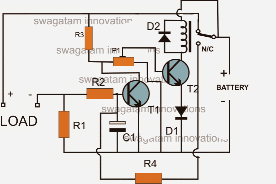
The"LOAD" terminals in the above diagram is supposed to be connected with the inverter +/- supply terminals.
This implies that the battery current from the right side has to pass through R1 before reaching the inverter, enabling the sensing circuit around R1 to sense a possible over current or overload situation.
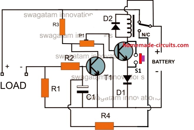
CORRECTION:
The above shown circuit will not initiate unless the relay is actuated manually through a push switch as shown below:
Parts List
- R1 = 0.6/Trip Current
- R2 = 100 Ohms,
- R3 =10k
- R4 = 100K,
- P1 = 10K PRESET
- C1 = 100uF/25V
- T1, T2 = BC547,
- Diodes = 1N4148
- Relay = As per the specs of the requirement.
Formulas and Calculations
Low Battery Cut-off Threshold
The low battery sensing is handled by R3 and P1 which forms a potential divider to set the base voltage of the relay driver transistor (T2). When the battery voltage drops below a set threshold the voltage at the base of T2 falls below Vbe (0.6V–0.7V) turning OFF the relay and disconnecting the load.
Formula for Threshold Voltage:
Vth = Vbat * (P1 / (P1 + R3))
- Where:
- Vth = Base threshold voltage (0.6V–0.7V)
- Vbat = Battery voltage
- P1 = Adjustable potentiometer resistance
- R3 = Fixed resistor
To calculate the battery voltage cut-off level:
Rearrange for Vbat:
Vbat = Vth * (P1 + R3) / P1
Overload/Overcurrent Sensing
Overcurrent protection is implemented using R1 which is placed between the base and emitter of transistor T1.
As the load current increases, the voltage drop across R1 rises. When the voltage across R1 reaches the Vbe of T1 (typically 0.6V–0.7V) T1 starts conducting and shunts the base current of T2 turning it OFF.
Formula for Overcurrent Trip Current:
Itrip = Vbe / R1
- Where:
- Itrip = Overcurrent trip current
- Vbe = Base-emitter threshold voltage of T1 (0.6V–0.7V)
- R1 = Resistor sensing the overcurrent
Base Current Limiting Resistor (R2)
Resistor R2 (optional) limits the base current for T1 to prevent excessive current through its base-emitter junction.
Formula for Base Resistor (if used):
R2 = (Vbat - Vbe) / Ib
- Where:
- Ib = Required base current for T1
- Vbat = Battery voltage
- Vbe = Base-emitter voltage of T1
For small signal transistors (e.g., BC547) Ib can be estimated as Iload / hFE where hFE is the DC current gain.
Inverter Overload Cut-OFF using Opamp
In the above paragraphs I have explained a very simple concept of inverter overload cut-off using only transistors.
However a cut off system using only transistors cannot be very accurate and sharp.
In order to get a precision inverter overload and short circuit cut off circuit the use of an opamp based design becomes imperative.
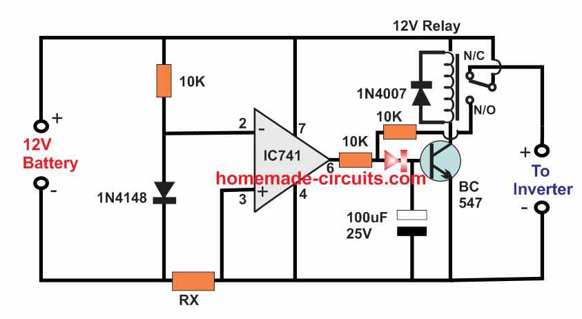
The following diagram shows a simple battery overload controller circuit using a single opamp 741 and a relay driver stage.
How it Works
The opamp is configured as a simple comparator circuit. he inverting input of the opamp is clamped at a fixed 0.6 V using a 1N4148 diode.
The non-inverting input of the op amp is connected with the negative line of the circuit through a over-current sensor resistor Rx.
Due to inverter overload or short circuit or over current conditions, a voltage drop develops across the resistor Rx which can exceed the 0.6V as per the calculated value of the RX, and cause the non-inverting input of the opamp potential to go higher then its inverter 0.6V potential.
This causes the op amp output to turn high activating the transistors and tripping the relay.
When power is first switched ON, and assuming the inverter is working normally without an overload, the voltage developed across RX is minimal, which keeps the pin3 potential of the opamp the opamp lower than the pin2 potential.
This allows the output of the opamp to be low ensuring that the transistor is switched OFF, and relay contacts stays at the N/C point.
Due to this the 12V is able to reach the inverter and operate it normally.
However, as soon as an overload or over current happens at the inverter side, a large amount of current passes through the RX resistor, causing a voltage drop to develop across pin3 of the IC.
When this voltage drop exceeds the 0.6V reference level of the pin2 of the IC, the output of the op amp goes high, causing the transistor to switch ON and trigger the relay.
The relay contacts now shift from N/C to N/O switching of power to the inverter and thereby averting the short circuit or overload conditions.
The N/O contact can be seen attached with the base of the relay driver transistor, which ensures that as soon as the an overload is detected the relay contact quickly latches the transistor, switching the power permanently off for the inverter.
The power can be restored only by disconnecting the 12 V battery input, but before that it must be ensured that the short circuit or the over load condition is appropriately removed from the inverter side.
Formulas and Calculations
Key Parameters
- RX: Current sensing resistor (ohms)
- Vref: Reference voltage at the inverting input (-) of IC741
- Itrip: Overcurrent trip current (amperes)
- Vdrop: Voltage drop across RX at trip current
Formulas
Voltage Drop Across RX:
Vdrop = Itrip * RX
- Where:
- Itrip = Overcurrent trip point (A)
- RX = Current sensing resistor (ohms)
Reference Voltage (Vref):
The voltage at the non-inverting input (+) of IC741 is set using a resistor divider or Zener diode (if used). For proper cutoff:
Vref ≈ Vdrop
Choosing RX (Sensing Resistor):
To calculate the value of RX for a given trip current:
RX = Vref / Itrip
- Where:
- Vref = Reference voltage (V)
- Itrip = Desired trip current (A)
Power Dissipation in RX:
The sensing resistor RX must handle the power dissipated during operation.
We will Use:
P = Itrip2 * RX
- Where:
- P = Power dissipation in RX (W)
Choose RX with a power rating higher than P for safe operation.
Example Calculation
Let’s assume:
Itrip = 10A (trip current)
Vref = 0.7V (reference voltage determined by the op-amp threshold)
Step 1: Calculate RX
RX = Vref / Itrip = 0.7 / 10 = 0.07 ohms
Step 2: Power Dissipation in RX
P = Itrip2 * RX = 102 * 0.07 = 7W
Choose a 0.07-ohm 10W resistor for RX to ensure safe operation.


Questions & Answers
No this circuit cannot be used in any manner for feeding a 3525 input, because the IC requires definite logic level which cannot be achieved from a transistor, you will have to incorporate a 741 IC for it.
New question about this: Could two of these circuits be hooked up to the same relay?
I have an RV with two sets of batteries: house and chassis. When the engine is running (the chassis battery is over 13V), I want to connect the two sets of batteries. When the house is plugged in (house battery over 13V), connect the two sets of batteries.
Also, if the voltage of either side goes over 16V, disconnect them (that part may be harder, and not an original requirement, it just occurred to me).
I was hoping to build two of these circuits, one hooked up to the chassis battery and the other hooked up to the house battery, and have a single relay connect the two batteries. I want to limit the current that crosses the relay to about 30amps (the max output of the house battery charger, as the engine alternator can put out 190amps).
I'm currently hunting for a relay that will strongly move to open when the coil isn't energized, as I don't want bumps in the road to accidentally flip the relay to the connected state.
Yes that would be possible, you just have to make the collectors of T2 common from the two circuits, and join with the relay coil.
For 30 amps you would need a powerful relay which would obviously have a tough electromagnetic connection, so hopefully it won't be rattled by the "bumps"
T2s will need to be appropriately dimensioned as per the relay coil ratings.
Hi, thank you for your great cutoff circuit. I suppose the cutoff voltage is changing by temperature quite large range in your circuit. A base-emitter voltage of the bipolar transistor has a temperature coefficient at least -2mV/C. That is not a problem because a battery to be charged only in specified temperature range.
you are right, thanks!
Make R3 = 22k, and R2 = 1k, that's all, other components will remain as is except the relay which should be 24V rated.
I easily get confused, after I drew the schematic diagram. My questions are;
1st:There are 3 connections for R3 preset, the 3rd will not be connected, right?
2nd: Where will the negative polarity of the battery be connected?
3rd: T2 base is connected to the 1K, while the other two terminals go to the positive and the ground respectively. Is the emitter the ground?
Could help me redraw the schematic?
And for just overload cut-off circuit, what would I need in a circuit and what would the schematic look like?
1) In the above updated diagram R3 is a fixed resistor P1 is the preset, yes, any two terminals of the preset can be selected, the center lead being the mandatory one.
2)the line which joins R1, T1 emiter, C1 negative and D1 cathode is the negative line.
3) please refer to the above diagram, I am not sure which diagram you are referring to?
Continuing the discussion of just having low voltage cutoff circuit. You mention(I'm quoting you) "Keep only D1, D2, T2 and the relay, eliminate everything else.
However R3 now gets replaced by a preset, the center goes to the base of T2, the other two terminals go to the positive and the ground respectively.
For safety add a 1K resistor with the base of T2 which then can be connected to the center tag of the preset."
ok following your instructions and basing from the updated diagram, lead me to redraw it to fit for a low voltage cutoff circuit imageshack.com/a/img443/5532/6s0f.png.
is that the schematic for a adjustable low voltage cutoff circuit?
the image link is not opening in my computer.
It should be OK if you have done as per the mentioned instructions.
Now i tried google drive, if you can view the image. https://drive.google.com/file/d/0BytEbOgq6mqeQU5mdzU4Yl9kUDA/edit?usp=sharing
R3 preset bottom free end should be connected to the negative line.
the indicated +/- lines are correct. The relay out is positive, the bottom rail is the negative.
Sir,
Can I use this circuit with sg3525 without relay?I am thinking that I can use a PNP transistor , am I right?
The above circuit is suitable only with a relay, for 3524 IC only an opamp circuit would be suitable
Hello Sir I want to make an overload protection circuit which can sustain upto 600Watts or as per requirement by use of Potentiometer. Please help me out how to modify this circuit for this purpose..
Hello Muhammad, you can do it by replacing R2 with a 1k pot. the ends of the pot will go to transistor base and R1, while the center will touch the ground
Hello Swagatam,
I have tried working with the Overload, Short Circuit and Load Battery Cut-Off Circuit but having challenges setting the cut-off voltage (10.5V) and getting the right value for R1. I want to use it for 2KVA inverter.
Secondly, can you help with a 12V, 100AH charger circuit with constant current charging and overcharge protection at 13.5V.
Thanks in this regard.
Hello Oluwaseyi,
if you are using a battery then the settings should be easier to implement, if the input is through a power supply then it would need to be regulated.
If you find it difficult then it could go for an IC based design.
You can try the last charger circuit for your 100 ah battery from the following link, just replace the shown LM338 with LM396 or LM196
https://www.homemade-circuits.com/2012/07/making-simple-smart-automatic-battery.html
Thanks for this circuit.
How can I modify this to use solid state relay?
It may be done wit the following mods:
Remove the relay and R4 entirely.
replace the relay coil connection points with the battery poles.
T2 may be upgraded as per the load amp specs.
Sir . Will you low battery cut off circuit, turn on the inverter when the battery is recharge?
it may be done by incorporating another relay parallel to the existing one and by wiring its contacts appropriately for the intended chageover
sir i need circuit for cutoff voltage with 2millivolt.
use any of the following circuits, replace 741 with LM311
https://www.homemade-circuits.com/2011/12/how-to-make-simple-low-battery-voltage.html
will that circuit need any other changes for cutoff voltage as 2 millivolt.
no changes would be required…it will respond even to the minutest changes between its inputs.
sir, you told that "https://drive.google.com/file/d/0BytEbOgq6mqeQU5mdzU4Yl9kUDA/edit?usp=sharing" is the circuit low battery cut off(to walkabout in above comments). i would like you to help me to modify this circuit to suit my needs. i am not a genius and just a beginner. so, i dont know whether my idea is correct and it can be done or not. i wanted to tell that when load is applied to circuit, and when its voltage decreases to preset level, it cuts off the relay. but when load is disconnected, i observed that the battery regains its voltage to some extent. so, then the circuit may connect the load again……so, i request you to modify this circuit such that, once it cuts the load, it should stay in cutoff position only until a reset button is pressed….can this be done to this circuit, sir? im just a beginner, so please help me ………
ss, there are two faults in the shown link, first the N/C should not be connected to ground, second, R3 other end must be connected to ground, rest everything looks OK.
it's highly unlikely that the relay would oscillate, due to the presence of the transistor hysteresis, so probably no latching feature would be required.
Sir, I connected the circuit in the correct way only as you said……before making this comment. But I failed to check the circuit diagram before giving the link(I erased n/c and connected r3 other end to ground but didn't save it but I thought I did). And thank you very much sir…now the circuit seems to be good working…..
OK, no problem, that's great!
hello sir, can this kind of cct can be modified to trip low standby current? thank you 🙂
hello shahirah,yes it can be done by setting the preset appropriately.
Thanks for time spending on this site. Sir can this circuit work for 3kva inverter? If yes kindly do the adjustment more so I need to know total calculation of R1. Thanks.
Yes it will work with 3kva inverter, just modify the relay contact accordingly and use 8050 for T2.
Sir ,
I didn't understand the preset part correctly can u explain its working in the given circuit
Vishnu. apply the lower battery cut off voltage to the circuit through an adjustable power supply and adjust P1 until the relay just deactivates, once this is setting is done the circuit would automatically switch OFF whenever the battery voltage reaches this level
How to make resistors of such low value 6miliohms etc here I am stuck do u have any idea pls let me know
use a couple of inches long non-plated iron wire, or a meter long copper wire wound on a former, tweak and adjust the lengths by verifying the ohms through a suitable multimeter.
hello sir
if the circuit current is 1.5A and i wanna cut-off at 10.5 volts which relay I have to use ?
if the cut-off volt is changed what is the rule to choose the suitable relay?
hello Mouhammad,
the relay has no relation to amps and cut off voltage of the design….you just have to choose a relay whose coil voltage is matching with the supply voltage of the circuit and adjust the preset such that relay just cuts off at the specified lower threshold….the adjustment will need to be made by supplying this lower threshold through an external power supply while setting up.
thanks so much sir
there is something else :
is this circuit re-activate automatically after it is deactivated ?
because if it cuts-off at (e.g 11 volts) , the voltage will be more than 11 volts with after the loading ends, so the circuit will be activated then deactivated many times
No that won't happen because of the transistors hysteresis properties…
ok that's good
but 'm facing a problem with relay connections
this is the diagram :
imagizer.imageshack.us/v2/280x200q90/537/zaHcTY.jpg
with the meter I've found the points (2,1) in the place of (3,5) and (3,5) in the place of (2,1) I don't know how or why
because I've found connection between the points 4 with 2 not 4 with 5 !
how can treat this please ?
If you can show me the relay image I can try to help, without seeing the relay image it would be difficult to locate.
this is a video I've recorded :
youtu.be/bi4bgS_6YEU
in the website of the store I've bought from , there is the diagram of points connections the same I told you
http://www.matni.com/Arabic/Relay/RELAY.htm
the relay model is T-73 and in the website I think it's the same JQC-3F(T-73)
the connections for this relay have been elaborately explained in this article, please check it out:
https://www.homemade-circuits.com/2012/01/how-to-understand-and-use-relay-in.html
well , I've made the circuit and put a red led to detect the passing of the current , and R1 = 3 resistors 2watt : 2x(1 ohm) and 2.7 ohm
I've tested it with 9v and 12v battery
when I change the preset the circuit doesn't deactivate !
although I've connected each point of the relay to the true point
can you help me please ?
thanks
youtu.be/AshLT5g010M
for setting up the low voltage cut off, you will have to connect the 9V source to the "load" marked terminals and then adjust the preset until the relay just trips, after this the source may be removed from the "load" terminals and the actual 12V battery connected to the "battery" marked terminals for normal operations
R1 has not related to the above setting. It determines the overload threshold trip point for the relay.
Hello Sir,
I assembled this circuit. However, there is not the voltage in the load with any level battery voltage (11V – 13.5V).
Hello Sir,
I assembled this circuit. However, the relay do not active when the bettery is 13V (0V in the load). When I remove T2, I connect direct from relay->diode-> mass, the relay actived (the battery is 13V, 13V in the load). I don't known why.