In this post I have explained a very simple digital panel type voltmeter circuit using a single IC L7107 and a few other ordinary components. The circuit is able to measure voltages right up to 2000 AC/DC V.
About the IC L7107
Making this simple digital panel voltmeter circuit is particularly easy due to the availability of the A/D voltage processor chip in the form of IC L7107.
Thanks to Intersil for providing us with this wonderful little IC L7107 which can be easily configured into a wide range digital voltmeter circuit using a few number of common anode seven segment displays.
The IC 7107 is a versatile, low consumption 3 and 1/2 digit A/D converter IC which has in-built processors such as seven segment decoders, driver for displays, set reference levels and clock generators.
The IC not only works with ordinary CA seven segment displays but also with liquid crystal displays (LCDs) and has an in-built multiplexed back plane illuminator for the connected LCD module.
It ensures auto zero correction for inputs less than 10uV, a zero drift for inputs below 1uV/oC, bias current for inputs of maximum 10pA and cross over error of less than a single count.
The IC can be set with ranges as high as 2000 V AC/DC, and as low as 2mV, the later makes the IC very suitable for measuring low inputs from sensors like load cells, piezo transducers, strain gauges and similar bridged transducer networks.
In other words, the chip may be simply configured for making products like digital weighing scale, pressure meters, electronic strain gauge, vibration detector, shock alarms and many similar circuits.
Needless to say, the IC L7107 can be also rigged into a simple yet accurate panel digital voltmeter circuit, which is what we are presently interested in.
Circuit Operation
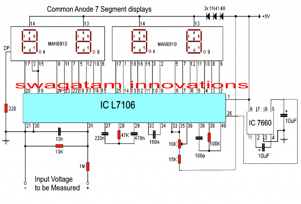
Referring to the circuit diagram below, the unit is a full fledged digital voltmeter circuit which can be used for measuring direct voltages right from zero to 199 volts.
The range can be appropriately widened or shortened simply by altering the value of the 1M resistor positioned in series with the input terminal. With 1M, the range gives a full scale of 199.99V, with 100K in place the range would become 19.99V full scale.
The circuit requires a dual +/-5V supply for operating, here the +5V may be strictly acquired from a standard 7805 IC regulator circuit, the -5V is automatically created by the IC 7660, and fed to pin#26 of the IC L7106.
The three 1N4148 diodes connected in series with the display supply line ensures optimal operating voltage to the displays for illuminating them with correct intensity, however for brighter illumination, the number of diodes may be experimented, as per personal preferences.
The 10K preset across pin#35/36 is used for calibrating the voltmeter correctly and must be set such that exactly 1V appears across pin#35/36. This will set up the circuit for displaying the measured magnitudes accurately as per the given specs, and datasheet of the IC.
Parts List
All resistors are 1/4 watt unless specified
- 220 Ohm - 1
- 10K = 1
- 1M = 1
- 47K = 1
- 15K = 1
- 100K = 1
- preset/trimmer 10K = 1
Capacitors
- 10nF Ceramic Disc = 1
- 220nF Ceramic Disc = 1
- 470nF Ceramic Disc = 1
- 100nF or 0.1uF Ceramic Disc = 1
- 100pF Ceramic Disc = 1
- 10uF/25V Electrolytic = 2
Semiconductors
- 1N4148 Diodes = 3
- 7 Segment Displays MAN6910 or Equivalent = 2
- IC L7106 = 1
- IC 7660 = 1
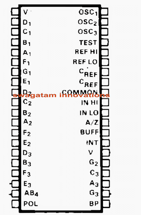
Pinout details of IC L7106 for interfacing with a 3 and 1/2 digital LCD display.

Questions & Answers
Dear Sir,
I am not a Electronic student and of chemistry. I don’t know how to design the needed PCB. Hence I requested in my last letter.
In Ic 741 Work bench multimeter can we change the analog signal to digital using Tl 071 IC and then feed it to LCD display/
please understand my problem.
Thanks and best regards.
mahandharma, yes you can get any readymade digital meter and replace it with the analogue meter in a IC 741 circuit. Readymade digital meter modules are cheaply available on amazon.
Mr Swagatam hi;
when I test the circuit with 3 single displays assigned for measuring the 0-99 volt, I can see the value 00.0 and the decimal display fluctuates between 1 and 2 (100-200 mV). however there is no any voltage value if other 12 volt voltage source is added to the circuit as their grounds are common.
Another point is that there is no display of the numbers but except dot if the capacitor
10 uf is placed between the pins 5 and 3 of the 7660. When I remove it then again displays show the 00.0 value.
so please I need your help.
Hi Suat,
This circuit is not designed me, it was referred from an external source, so unfortunately I cannot provide any help with this circuit. You can perhaps try referring to the datasheet and see if you can find any relevant information….
thanks in according to the 7107 datasheet I think the problem is the pins 32 and 35 should be conected to the Vin(-) too since they should be low while measurement process
OK great, glad you could find the solution so soon…
Hi. I am trying to make a bipolar DC voltage polarity detector circuit that is able to receive voltage within the range of -10V to 10V and indicate the polarity of that voltage. Initially I had tried to solve this using 2 comparator op amps, one for negative and the other for positive polarity detection however, the output of the op amps give a voltage close to -Vcc as I’m using a dual rail power supply. I am also using a atmega microcontroller which reads the Analogue outputs from the 2 op amps and in order to visually indicate the polarity of voltages however they can’t take any voltages out of the range of 0-5v. How can I solve this problem?
Sorry, no ideas about it…I am having difficulty figuring out the issue.
Thanks Sir. I am making a DC Voltmeter. I have a dual rail power supply unit and was uncertain as to what purpose the Dual Slope integrator circuit serves for a DC Voltmeter especially when dealing with voltages of different polarity such as in this case. Could you please provide some clarity if possible
Hi Dylan,
The dual slope integrator is a type of analog-to-digital converter (ADC) that is commonly used in digital voltmeters. Its primary purpose is to measure the voltage level of an input signal and convert it into a digital value that can be displayed. The “dual slope” part refers to the two slopes or ramps that are used in the integration process.
Hi Sir , Do you have an email that I can use to get into contact with you to ask further circuit related queries.
Hi Dylan,
I usually discuss the issues through comments only, so you can feel free to ask your questions here.
Sir, This circuit has been very helpful. Is there any option or circuit to view ampere. (I searched for 3161 ic but I couldn’t find anywhere)
Thank you Sreeraj,
I think I have a related post on the IC 3161, you can check it out here:
https://www.homemade-circuits.com/how-to-make-digital-voltmeter-ammeter/
Thank you sir…
hi, can this circuit measure for ac voltage?
Hi, sorry no, this circuit cannot measure AC voltage
Ouh, but I’ve seen that you replied someone comment that him wan to use this circuit for house hold ac voltage? Can u guide me .
You can measure mains ac voltage after rectifying it through a bridge rectifier, but it will not show the RMS value of the mains rather it will show the peak value, meaning, for a 220V AC input the reading will be 310V and so on.
The electrolytic, (10mfd), attached to pin 26 of the 7106 is the wrong way around. This is the negative voltage input pin from pin 5 of the IC7660.
OK, thank you for the feedback, it will help the readers to correct the schematic appropriately.
would it work if I use 4 single 7 segment display? I can’t find MAN6910 in my area
if the pins are correctly matched then it might work
Hi Swagatam,
I have 2 questions:
1. Why i cannot leave a reply under this post “Transformerless AC Voltmeter Circuit Using Arduino”? It is a site bug?
2. Still refering to “Transformerless AC Voltmeter Circuit Using Arduino” how much current it can handle? It can be used to measure home-devices like 2500W vacuum cleaner?
Hi Davide, it is not a bug, the comment box is disabled since I am not an expert with Arduino and therefore cannot answer related questions.
Current is never relevant to voltmeters. The current can be any value as long as the voltage is within the maximum specified range of the meter. Similarly it can handle any wattage as long as the volt is within the specified max range
Hi. As always good explanation and good project. Meanwhile i have some questions :
– By setting Vref = 1v The max vinput is then set to 2v . Isn’t it?
– The voltage divider across pins 30 and 31 is here for setting the range of the voltmeter. Then is it correct that removing the 1M resistor will allow to have a range of 2v (equal to the max vinput) ?
– In case of a range of 2v what is the resolution (accuracy) in mv ?
Thanks again.
Hi, sorry I don’t remember the working and the specifications of the IC, it was written a long time ago.
I think the datasheet of the IC will have the answers.
Dear Sir,
IC 7106 is desisgned to drive LCD display (meanwhile 7107 is for 7seg LED display). In ur circuit, I wonder if the IC could supply current eanough for 7 seg LED display? The circuit is only work with dual supply voltage or it could works with single voltage?
Thanks and best regards,
LamNH
Dear Lam, the circuit will work if connected exactly as suggested in the diagram.
The title is “Digital Voltmeter Circuit Using IC L7107” but the circuit showing IC 7106. Is that corect? Pls confirm. Thanks!
Both have similar features except the digital display, so you can use any one of them depending on the display.
Thank you for doing this kind of website. I love it. One problem however, a seperate bom would be awesome. I am old and kinda blind. Hard to see the values of the components. I think they are capacitors, but the “n” is throwing me off. Please enlighten me. Thank you kindly sir.
Thanks very much for liking my website! I have added the parts list for your reference!
“n” means nano, or nanoFarad (nF) for the designated capacitors.
hello sir
I wanna measure 0.001v – 5v, which ic is good for this (analog to digital converter ), Is this possible to measure this voltage range
hello alwin, digital will be obviously better….yes it is possible to measure this range with any good quality DMM
sir
You Use Two 7 Segment display. If I Want To Use One 7
Segment Display ..! What Should I do…… Sir I using A Variable DC Power Supply Unit But I Have No ckt Diagram for Digital Volt Display.
thanks for your compliment.
Dada, I don't think a single display would be possible with this IC, because the IC is specifically designed to drive a 3.5 digit display
can i interface it with any microcontroller(8051 or AVR)?
yes, you can do it…
Sir,
I have a digital voltmeter which measure the 24 volt dc.
When it was new then voltage was measuring ok. But after 2 months, voltage reading fluacting in display. I mean it show 25,32,47 volt etc.
How to stop the wrongly fluction on display??
Nitin, if it has a selector switch then the problem could be in the switch, just move it rapidly up/down and then check the response….loose prod connectors could also be an issue, so you can check it as well.
if these are OK, then your meter is surely malfunctioning.
Sorry if this comment posted more than once. I've had a hard time submitting it.
I'm wondering if this circuit could output the voltage reading to an Arduino instead of the LEDs? I'd like an Arduino to be able to read voltage and store the value as a variable in a program.
Will this meet that need?
I am sorry I have no idea how this circuit may be configured with an Arduino…
Can this Circuit can be used to measure AC house hold Supply. ??
yes, after appropriately rectifying and calculating the input resistors
Sir it is directly connected to the AC output voltage of the generator set to measure its output voltage or it is only used to measure DC voltage?
convert AC to DC and then the 10K preset across pin#35/36 could be used for calibrating the voltmeter correctly and must be set such that exactly 1V appears across pin#35/36. This will set up the circuit for displaying the fed magnitudes accurately.
Thanks for reply sir. Why its called 3 and half digital display ..