In this article we investigate a electronic circuit design which works like a conventional fuse for safeguarding any electrical system from overloads, over-current, short circuit and related fire hazards.
However, the main advantage of this electronic fuse is that it does not require frequent replacements like mechanical fuses, instead it can be reset with a single push of a button.
What is a Fuse
A fuse is a device used in electrical wiring for preventing accidental fire hazards due to to a short circuit or overloads. In ordinary mechanical type of fuses, a special fusible wire is used which melts when there's short circuit at some point in the wiring.
Though such fuses are fairly reliable, are surely not so efficient or elegant with their performance.
A mechanical fusible type of fuse requires careful selection as far as the rating is concerned and once blown, again requires careful replacement of the device correctly.
Even automobiles incorporate largely the above fusible types of fuses for the discussed precautions concerns.
However the above inefficient fuse can be very effectively replaced with more versatile types of electronic fuse circuit with little consideration.
Main Features
If you search for an electronic fuse circuit online, you may come across a few very ordinary designs which actually have no ability to handle high current short circuits or overloads.
These circuits are created by school kids and cannot be used for serious applications.
The design presented below uses a relay and is capable of supporting high current short circuits up to 5 amps or even 10 amps.
This makes the design suitable for almost all high current DC circuits which demand a fool-proof short circuit protection.
How this Electronic Fuse Works
The idea has been exclusively developed by me and the test results were pretty impressive.
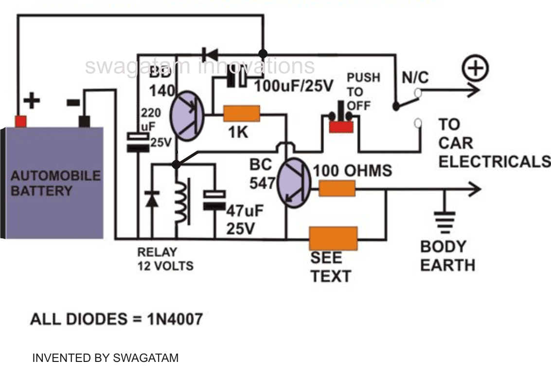
The CIRCUIT DIAGRAM is very simple, a relay is used to switch the battery power to the rest of the electrical of the vehicle via its contacts.
A low value resistor is placed across the base emitter of a transistor for sensing the rise in the current levels.
When a possible short circuit is sensed, an equivalent amount of voltage is developed across this low value resistor, this voltage becomes responsible for instantly triggering the transistor which in turn triggers the relay driver stage.
The relay quickly reverts and switches OFF the supply to the vehicle electrical.
However in the process it also latches itself so that it does not go into an oscillating mode.
The relay contacts must be rated to handle the maximum allowable current specified for the vehicle's normal needs.
Sensing Resistor
The value of the sensing resistor should be carefully selected for the intended tripping operations at the correct over load levels.
I used an iron wire (1mm thick, 6 turns, 1 inch diameter) in place of the sensing resistor and it could handle well up to 4 amps after which it forced the relay to trip.
For higher currents lower number of turns may be tried.
To be precise, the sensing resistor could be calculated using the formula:
- Rx = 0.6 / Cut Off Current
- Rx Wattage = 0.6 x Cut Off Current
The "push to OFF" switch is used to reset the circuit, but only after the short circuit condition is properly rectified.
A simple electronic fuse circuit developed by me is shown below:
Another Simple Electronic Fuse
The electronic fuse signifies that load current is shut off as soon as an overload is detected. Actually it simply restricts the load current to a magnitude of certain amps. The next circuit will basically trigger the load current to drop to 0 %.
In case it rises, causes IL x R2 > 0.7V/R2, Q4 to switch on, delivering base current to Q3. Q4 as a result activates, providing additional base current for Q4.
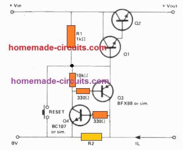
Regenerative function goes on until eventually Q4 and Q3 are saturated. Q3 will subsequently take off all base current from Q1, consequently turning Q2 off and enabling the load to be safe from over current.
In case the reset button is pressed, the entire current drive shall be taken off from Q3 and Q4, causing them to be void of saturation.
As soon as the reset button i released, the circuit is going to either go back to original situation in case the overload situation has been eliminated, or will click off yet again in case it is still existing.
Care must be observed with the "grounding" to prevent shorting of R2.


Questions & Answers
Do you have a circuit for inline between car cigarette lighter and DC laptop charger, low voltage disconnect stopping power EITHER
♦️ total watt draw exceeds 110
Or
♦️ voltage drops below 12.6
Hello Mr. Swagatam
I need a fast electronic fuse circuit to protect the MOSFETs and the MOSFET driver in an H-bridge. Is this circuit fast?
My H-bridge circuit is 5 Amps of current, and the operating voltage is 80 Volts.
Hello Mazloumi,

There’s no need to put a fuse, you can simply safeguard the MOSFETs using snubbers and a shut down activation of the H-bridge IC, as shown in the following figure, around the left side BC547 transistor:
Hello Mr. Swagatam
thank you for your reply.
My driver is ir2111.
In the IR2111 driver, will the same circuit be used, or will the values and the circuit itself change?
Mazloumi, I think IR2111 does not have a over current shut-down integration in the IC, so you can configure it in the following manner:
For further discussions please comment under IR2111 article.
thank you for your reply.
How much should I set the value of rx to?
Please refer to this article:
https://www.homemade-circuits.com/ic-ir2111-h-bridge-inverter-circuit-with-shut-down/
Dear Swagatam,
For the second circuit, if I don’t have the reset switch, will the circuit reset after going through a power cycle?
Hi Ganesh,
No, without pressing the reset switch the circuit cannot be reset. You can reset it by either pressing the button or by switching OFF and switching ON the power supply to the circuit.
Thank you Swagatam,
Is there a way to replace Q1 and Q2 with a MOSFET?
I think Q2 can be replaced with a MOSFET, Q1 will not be required in this situation.
Could you explain why the resistor values for R1 is 1k? and why for another resistor 10k is selected?
It depends on the transistor specifications. R1 decides how much maximum current Q1/Q2 can handle. Due to the high gain of Q1/Q2 any resistor between 1K and 10K can be used for R1 so that Q2 can deliver sufficient output current.
The 10K ensures that Q4 does not burn due to high collector current. Again this 10K is not critical and can be any value between 4k7 and 15K.
Thank you.
Is it possible to have the sense resistor on the positive line?
It will the circuit very complex and will need to be redesigned, so it is not possible to put the current sensing resistor on the positive side.
Swagatam,
On the second schematic do you have a part number for Q1 and Q2?
Hi Curt, Q1 and Q2 values will depend on the current spec of the load. Typically for loads below 1 amp you can use 2N2222 for Q1, and TIP31 for Q2. Alternatively you can replace both the transistors with a single TIP122
Dear Swagatam
would you please do a favor and send me a high quality photo of yourself?
I want to know better the man that is so good and kind and helps other people of all countries.
Best regards
Ali
Thank you Dear Ali for appreciating. I am always happy to help, I’ll try to post a picture soon.
Dear Sir Swagatam
Hello and thank you so much for your great favor. Your response not only solved my problem and made me very glad, but also learned me to use the proper word; blowing the fuse instead of burning the fuse.
I desire you healthy and the best
He who never forgets your kindness
yours truly
Ali
Dear Ali,
I am glad I could help you! Wish you all the best in life.
Dear Sir Swagatam
Hello and thank you very much for your awesome site. I appreciate you for helping others so generously. I have tried your ” precision LDR light detector ” for lighting a 220 volt, 100w Lamp and the circuit works well but both the Lamp and the 2 or 3 Amp mechanical fuses burn after 2 or 3 months and I am sure that the problem refers to the electrical wiring of my apartment. I am writing to tell you that I have decided to use thin copper wires instead of fuses and solder the copper wire to metal sides of the burned glass fuses instead of buying new ones. So, is there a table or formula for calculating the diameter of copper wire needed for substituting the mechanical fuses of different Amp ( up to 5 A ) ?If not, would you please do a favor and write an essay in this regard? I have a Vernier caliper for measuring the diameter of wires, too.
Sincerely yours
Ali
Thank you Ali, and Glad you could make the circuit successfully. Yes the fuse and the lamp may blow if there’s too much of fluctuations in the mains voltage. If you are using a copper wire then make sure it is very very thin, because copper has a high melting point therefore a relatively thicker wire might not blow quickly, damaging the bulb.
I do not have a formula or chart for the wire selection, but approximately, the wire can be a 36 SWG wire, that must be quite OK for the fuse.
Or the best thing could be to use the solder wire itself as the fuse wire, because solder wire has a low melting point and will work better like a fuse wire. A 22 gauge solder wire will be quite OK.
Hi Swagatam
Many thanks for your help with this, much appreciated. I’ve been looking for a short circuit protection solution for a long time, especially one that reacts virtually instantly. I’ve already blown 2 transformers in the past.
Your site is awesome and the fact that you share and help others in this field is even more so.
I commend you Sir.
Best Regards
Andre
My pleasure Andre, I wish you all the best with the project!!
Hi Swagatam
Thank you very much for your prompt reply.
In my case I would like the cut off current of the sensing resistor to be at 2A.
Using your formula
Rx = 0.6 / Cut Off Current = 0.6 / 2.0 = 0.3 Ohms
Rx Wattage = 0.6 x Cut Off Current = 0.6 x 2.0 = 1.2 Watts
Is this correct?
Many thanks
Andre
Hi Andre, That looks fine to me. You can go ahead with the values.
Hi Swagatam
I am a hobbyist with minimal electronics knowledge. I am hoping to use your fuse circuit on my slot car track for short circuit protection, which occurs often when a slot car de-slots and the guide braids go across the negative and positve guide rails on the track causing a short circuit to occur.
My power unit is a 13.8V/3A regulated DC supply with an on-board 3A glass fuse .
My questions to you are as follows –
-would the 1K and the 100 ohm resistor values need to be changed?
-would the 220uf, 100uf and the 47uf capacitor values need to be changed?
– are these capacitors bi-polar?
-can non-polarized capacitors be used, if so, how are they orientated in the circuit?
-I calculated a 5.6 ohm 34.5W resistor for the current sensor based on 2.5A
Looking forward to your response
Best regards
Andre
Hi Andre, yes surely you can try the above design for your application.
The parts are not really critical except the sensing resistor. I have updated the formula for calculating it in the above article, which you can implement accordingly.
The 1K could be changed to 10k since the relay in your case can be any ordinary 7 amp relay
What is the purpose of the 220UF capacitor across the battery ?
To ensure better stabilization and reliability while the tripping happens.
HI. Is there a circuit which protect from short circuit and reverse polarity at the same time ?
Thanks.
Reverse polarity can be simply prevented through a rectifier diode…
I forgot to mention that the reverse voltage and short circuit protection is to be placed between a charger and a battery.
Yes but the voltage drop is too high with a rectifier diode. I’m looking for a circuit based on a channel mosfet to reduce the voltage drop to minimum. Thanks.
Then you can try the concepts presented in the first and the second diagrams from this article
https://www.homemade-circuits.com/simple-zero-drop-solar-charger-circuit/
Hi Swa,
Can you please explain the function of the doode at the emitter of the BD 140.
Thanks
Kanta
Hi Kanta, it's not critical, however it guarantees a more reliable triggering of the BD140 and also a better charge holding capability for the 220uF capacitor
Hi Swa,
I am planning to use this protection circuit for a higher voltage DC which is about 40V. How do i modify the latching? Please kindly give me advice.
Thanks
Kanta
Hi Kanta, since the relay is 12V the emitter of BD140 will need to be connected with a 12V source derived from the 40V…and similarly the feed coming from the push switch will need to be passed through a 7812 IC before it connects with the relay coil
rest everything can be as is
Hi Swagatam,
What if instead of a reset button and oscillation, I direct, upon switch off of the relay, to another load? Do I have to remove the push button wiring? Thanks…
Hello there, Swagatam,
As you say, during a short circuit or overload, the relay switches off hence, latching itself and goes into an oscillating mode. What if instead I connect it to another load after the relay is switched off? Do I have to remove also the push button connection or just retain it for resetting?
……wish you too a very Happy New Year!!
Hi Edgar,
The drop may be because of the relay coil consumption which could be due to its lower resistance value, try using a higher coil ohm relay and check the response
Hi Swagatam bai,
First of all, a new year's greeting to you.
I have successfully tested your circuit and it really works!
When it senses an overload based on the sensing resistor or a short circuit, the relay energizes and latches the NO contacts. But I noticed a drop of 1 volt in this situation. I am using LEDs as load to visualize the switching and my power supply is around 0.6A/12Vdc.
I would like to know what is causing the voltage drop?
Cheers!
It means there's something not correct in your circuit, check the voltage across the 0.33 resistor…. this voltage would be responsible for triggering BC547 and the BD140.
Make sure the supply voltage source is on the left side as exactly shown in the diagram.
Load current reached 3A and it didn't trip at all. When power source is switched-off, it's then that relay coil is energized for a second. Will test individual components.Thanks again & cheers to you Swagatam.
Hello Edgar, you did not explain about the exact results you are getting, did it trip a lot earlier or did not trip at all.
If it's not tripping at all there could be some serious fault in your wiring or the components, if it's tripping at lower than 1.8 amp in that case you can try reducing the 0.33 to some lower value.
The circuit has been thoroughly tested by me and will surely work
Hello there Swagatam,
The low value resistor you stated has 6 turns but length of the 1mm wire is not indicated. What's the exact value of the resistor, is it R=0.6v/trip current? If yes, I placed a 0.33R to trip at 1.8A, but in vain. Regards.
Hello Edgar,
I think there are many typos in the above article explanation, I'm sorry about it
Actually it should be: "However in the process it also latches itself so that it does NOT go into an oscillating mode…."
Please read it as corrected here, I'll make sure the same is done in the above article also.