The following article discusses a simple automatic micro UPS circuit which can be used with modems for acquiring uninterrupted power from a DC source, and battery during mains power failures. The circuit also incorporates an automatic over charge cut off, and a low battery indication feature. The circuit was requested by Mr. Kapil Goel.
Technical Specifications
Hi Swagatam, How are you, and was really happy to read your blog as I was scrolling through circuit sites for my requirement.If you can help me out for that, I have a requirement:
This is exactly what my requirement is: I have a 12volt operated device, it consumes approx 35 watts right now I power it up using a 12volt adapter, but when main power fails its get rebooted..
I wanted to use 12volt 2200mh Li-ion battery pack so that whenever there’s a power cut it will automatically shift to battery.
Also, the circuit should have over charge protection, and low battery indicator.
At last I am not asking this circuit for free, as I am ready to pay for it. Many thanks in advance
Regards, Kapil Goel
UPDATE: New Simplified Micro-UPS Circuit
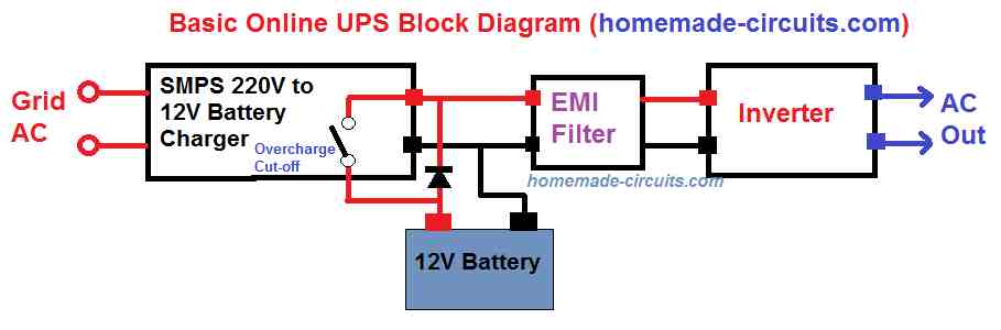
No need to build the op-amp based complex circuits explained in the following article. You can simply build and the implement the below shown simple micro-UPS circuit for your modem UPS application:
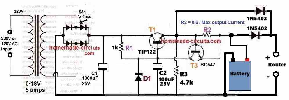
The zener diode D1 value must be selected such that the output voltage across R3 is slightly less than the maximum full-charge level of the battery. For example, if the maximum full charge level of the battery is 14.3V, then select the D1 value appropriately which generates around 14V across R3.
The R2 value can be calculated using the following formula:
R2 = 0.6/Battery charging current.
For lead acid battery, the suitable battery charging current can be around 10% of the battery Ah, and for Li-Ion battery this can be around 50% of the battery Ah.
Micro-UPS Circuit with Battery Over Charge Cut-off using Op-amp
The design was actually presented in one of my earlier posts also, however it does not include an automatic over charge cut off feature.The present design has similar functions, but has an added protection feature in the form of an automatic battery over charge cut off and also an under voltage indicator.
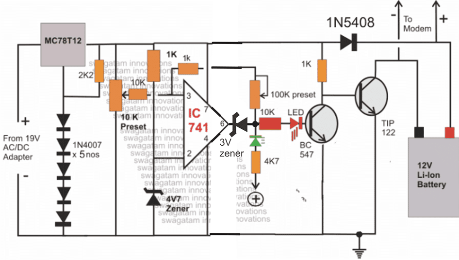
The proposed circuit diagram of an automatic micro UPS may be understood with the following points:
The input supply is acquired from any standard AC/DC adapter rated anywhere within 15 and 19V DC, current at anything above 1.5 amps.
The above supply is regulated via a 7812 IC whose ground pin is elevated to about 2.4V so that the output from the IC gets raised to about 14.4V rather than the normal 12V.
This is required because the attached 12V battery needs to be supplied with a slightly higher potential than its rated value.
How the IC 741 is Configured
The 741 IC stage is configured as a comparator.
Its pin#2 is clamped to a fixed reference voltage of 4.7V using a suitably rated zener diode.
Pin#3 is rigged as the sensing input if the IC via an adjustable preset.
The preset is adjusted such that the potential at pin#3 just exceeds the potential at pin#2 when the battery voltage crosses the 13.5V mark.
As long as the above situation is not sensed, the output of the IC at pin#6 sticks to it initial zero voltage level which in turn keeps the BC547 transistor switched OFF. With BC547 being switched OFF, the TIP122 gets a chance to conduct via the 1K resistor and charges the connected battery.
The battery terminals are directly connected with the modem which is being used for some application.
This allows the modem to remain powered via the external AC/DC adapter while the battery gets charged simultaneously.
The battery is allowed to charge freely until it reaches the over charge threshold when the output at pin#6 of the IC goes high, switching ON the connected BC547 transistor.
The above switching cuts off the base bias to the TIP122 transistor and stops the battery from getting further charged. This does not affect the modem as it continues to acquire power from the external power supply.
During mains failure, the supply from the external adapter gets inhibited, and the modem starts receiving back-up supply from the battery.
Since no relays are used the transition is within micro seconds which keeps the supply to the modem interrupted during power failures or even under heavy power fluctuations.
If the mains stays absent for long, and the battery reaches its over discharge threshold, the situation is immediately indicated with the green LED, which can be also replaced with a buzzer. The modem should be switched OFF then, to stop damage to the battery due to over discharge.
The adjustment of the 100K preset determines the low voltage threshold mark or the lower indication. level.
Once the green LED is lit, it will remain lit until the battery is fully charged, similarly once the red LED illuminates, it will stay illuminated until the green LED lights up or when the battery voltage level falls below the set lower threshold.
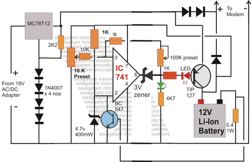
Using a PNP BJT for the above Charger Circuit
The above circuit can be also configured in the following manner, here the LED indications get reversed, meaning red LED shows low voltage while the green LED indicates high voltage threshold.
The following circuit also incorporates a current limiting facility which can be used for providing a current controlled charging to the connected battery.
FEEDBACK from Mr. Kapil
Hi Swagat,
Thanks for the circuit.. I really appreciated your swift and kind response..
I have couple of questions on the same.
1) What will be the max current it will support, my device requires atleast 5 amps 12 volts, will this be able to handle that.
2)As per the circuit, I can see, you have directly connected the modem to the battery, but if I am not wrong, this means that modem will keep on taking the power from battery, and battery will not get charged?
Please I clear out this confusion.
Also I am using a li-ion battery, which has a voltage of 12.6 volts on full charge and 11 when discharged.
Also my input volt is also 12volts, I cannot use a higher volt rated adapter.. will it be able to charge my battery at fullest.
Regards,
Kapil Goel
My Reply
Hi Kapil,
Presently the above shown circuit is rated at 3 amps maximum, so I may have to amend the design to suit your requirements, however the input voltage will need to be above 13V otherwise the battery will never get optimally charged.
The direct connection of the battery with the modem will not affect the battery charging as long as the input source power is active....both outputs will be simultaneously taken care of.Regards.
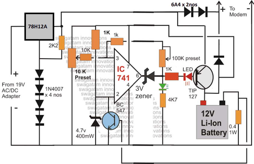
The modified 5 AMP micro UPS circuit design:



Questions & Answers
Gentilissimo Ingegnere Swagatam
Ho scoperto il suo prezzioso sito, con l’occasione le porgo un mio problema, possego un inverter di 1000 watt, vorrei collegare alla rete in modo che quando va via la luce l’inverter si accende in automatico e viceversa puo’ farmi avere un circuito non troppo complicato, nel mio paese ci sono 230 vl.
Aprezzo il suo sito e’ sopratutto la sua professionalita’ e’ gentilezza.
Un grande saluto dall’ Italia. grazie
Thank you Tommy,
If you want to convert an inverter into an UPS, then you can simply use the concept explained in the following article…
https://www.homemade-circuits.com/how-to-convert-inverter-to-ups/
Please reply sir 🙏
Rolland, I have already replied to all your previous comments, please check then again…
mc78t12 and 78h12a components, can they be replaced with other components, because these components are not available in my location?
You can replace them with this circuit:
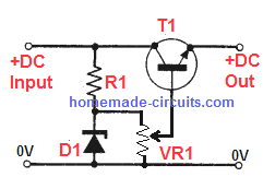
sorry my friend, can you send me a wiring diagram, to replace the 78H12A component, because I saw the picture you sent and I don’t know what kind of transistor it uses?
Hello Rolland, here’s another diagram, you can try:

You can replace the transistor with a TIP122.
The zener diode can be a 13V zener which will give you an output of 12V.
can you help me design one, to replace 78H12A?
That circuit is unnecessarily too big,, i can make it smaller, please tell e your complete requirement I will try to provide you the appropriate circuit design…
3x wifi routers 12v/1.5amp, please help?
You can try the following concept:

Assuming the routers consumption is 3 * 1.5 = 4.5 Amps, all the diodes should be 6A4 diodes.
The TIP122 must be also replaced with TIP142.
Battery should be rated at 12V, 20 Ah.
Zener diode D1 must be selected such that the voltage across R3 is equal to the full charge level of the battery (without battery connected)
Good day Mr Swagatam,
thanks for your awesome website you have.
Q. Can the li-ion battery be replace by a lead acid battery in the same curcuit.
kind regards
Moerdyk
Thank you Moerdyk,
Yes you can replace the Li-Ion with a lead acid battery. Just make sure the input current is not more than 10% or 15% of the battery’s Ah rating
Your comment is awaiting moderation.
I have made the pnp bjt circuit. And when i give power in power pins just green led bright shine and red one also lighting in little shine. And even i provide power in only battery pins also same happening. Should i connect battery and power togeather at once to work this? And also when i turn 10k preset only green led goes to dim mode and never completele shut off. And 100k preset do nothing. But i never tried circuit with battery and power both at once. Only trying to test. Please help me.sir.
And sir please tell me how to wire this 100k preset correctly? Maybe my circuit issue is with this preset.
Please remove the 100k preset and the 1K series link, it may be difficult for you to set it up, because the process is complex. Anyway, it is optional.
When green LED shuts off the red LED must illuminate. If this is not happening then something is not correct with your PNP transistor.
I would recommend you to try the first circuit with NPN transistor because it is easier to understand and set up. But again remove the 100K preset link it is not required.
I have connected all correctly but nothing changes. When i rotate 10k only green led status changing no complete shut off any led. Always one goig dim when i rotating 10k preset. And 100k preset do nothing. I can not understand whats wrong. Please help me
Hi, Did you try the first circuit as recommended by me earlier?
If you are newcomer in the field of electronics then you will have to do it step-wise manner.
Please build the first circuit and
Dear Mr. Swagatam,
Greetings from Sri Lanka. First my appreciation of your untiring effort to generously answer each and every question or comment, this is rare in Youtube.
My question is about using three (3) 3.7v 18650 Li-ion batteries instead of a single 12v battery. Could you propose a modification to accommodate this request? Frankly I tried a number of mini UPSs as per some Youtube channels using 3.7v batteries with 3S BMS and Booster converters. But did not succeed in holding the backup for more than 5 minutes for my wifi router. I am using some good Samsung batteries taken out of laptop battery packs.
Look forward to your kind response since our country is going through sever economic crisis and has long our powercuts.
Thank you very much Upul, I appreciate your kind thoughts.
No modifications would be required in the circuit for 3nos 3.7V Li-ion cells in series, except the voltage regulator IC, which can be removed in this case.
If you are not able to get proper back up time, then it is not related to the circuit, rather it is related to the battery or the modem specifications. If the batteries are old or degraded then the backup time will be less, or if the modem is drawing high current also then the battery will discharge quickly and provide lower backup time.
You can connect an ammeter in series with the modem positive line and check how much current the modem is consuming from the battery, this will prove whether the battery is faulty or the modem current is high compared to the battery specifications.
Sir i found 1ohm 1w can i use 3 of them in parallel to get .4 ohm 1w??? And i found 5.1v 1w zener or 3.3v 500mw zener.. can i use any of them??
Arnab, yes you can use the mentioned resistors in parallel, and use the any of those zener diodes.
I think the BC547 feedback with the 0.4 ohm can be eliminated and instead we can provide a current controlled stage at the input stage using LM338 or a simple transistor circuit.
The BC547 stage can be eliminated for simplicity and to avoid confusions during troubleshooting if something goes wrong.
I can provide the alternative diagram if you wish to see it.
Obviously, if you can show it.. it will be the best sir..
Here’s the finalized design, make sure to check all the new modifications included in the circuit, and the things which have been removed:
Actually i already bought the components for 5amp modified which is using 10k and 100k so thought that lets try once. No input was in dc terminal, in the battery terminal i gave 14.3v (100k disconnected) i set the 10k value just to light up the green. (Red goes off). Then connected the 100k without losing the power in the battery terminal (still dc input disconnected) then made the voltage input in the battery terminal in 11V. And adjust the 100k to just shut off the green led, and red lights up. Now, i gave 19v in dc input (disconnected the battery side input)to check the output in modem side. Also in the battery side i got 6 v in modem side.. 0v in battery side..
And also tried disconnecting the dc side and giving 12v in battery side got 13v output in modem side.
Your setting up procedure is OK, but you must have a battery connected at the collector side of the transistor otherwise the circuit will not be able to detect the battery voltage and the circuit will remain switched OFF. You can see in the diagram that IC 741 supply lines get the voltage from the battery, so battery must be connected for the circuit to work.
you can remove the 100K preset link, it is not crucial, according to me.
Sir last one thing from ic741 pin 7
connects with pot 10k to ground and from pin 3 one 10k connects with them OR there is a pot 10k between pin 7 and 3 and connects to ground. Just elaborate me that part.
Sir I tried 5amp modified circuit. But i used lm317t .. the 10k and 100k pot was set as per your information. But when i am giving 12 input instead of battery in the battery input(dc disconnected). I got 13v output in the modem side.. and when i was giving 19v input(12v 3a adapter and xl6009 boosted to 19) i was getting 6v in modem side and 0v in battery port. I can’t understand why this is happening. ( I used 2 6a4 just before the modem output, and 1 6a4 in between the battery and modem side.) Should i replace all tahe 6a4 to 4007???.
Arnab, there’s no 100k pot in the modified diagram. Please do it exactly as shown in the following diagram:
You said you adjusted the preset correctly, so did the LEDs respond accordingly?
For adjusting the the 10k preset you must provide the maximum cut off voltage across pin#7 and pin#4 of the IC 741, and then adjust the perset so that the green LED just lights up, and the red LED shuts off.
Once this is done you will have to connect the battery across the indicated position, and then switch ON the input voltage. Remember the circuit gets the voltage from the battery and then detects its voltage level. unless the battery is connected the circuit will not initiate.
….Since your are using LM317, the current controller stage can be removed.
Arnab, the 10k preset has 3 terminals, the center terminal goes to pin#3 through a 10k resistor. Out of the remaining two outer terminals of the 10K preset one goes to the line which is connected to pin#7, and the other goes the ground line.
Thank you, Sir, for your quick reply, your project is very helpful. some things I need to know that,
1> MC78T12 also LM338 is not available, can I use LM1085 – ADJ (3A Adjustable Low Dropout) or LM350T or LM317 for my purpose? as I want 1.5 – 2 A output max.
2> For the second circuit can any replacement for .4 ohm resistor?
You are welcome Arnab, yes you can use the mentioned ICs, they are all good regulator ICs.
for 0.4 ohms you can put 4nos of 0.1 ohms/ 1 watt resistors in series, because 0.1 is easy to get.
Thank you sir, two more things to know.
1. For the second circuit 4.7v 400mw zener is unavailable, i found 4.7v 500mw and 4.7v 250mw which one to use?? And what is the 3v zener wattage??
2. For the second circuit all the resistors are 1/4 watt right??
Hi Arnab,
Both the zeners will work, you can use any one of them. The 3V zener can be eliminated and replaced with a wire link, since we already have an LED at the base of the transistor.
all the resistors can be 1/4 watt, except the 0.4 ohm, which can be calculated as = 0.6 x battery current limit
can you send me the components list for 3A supply?
You can try the first circuit, all the part numbers are given in the diagram, you just have to copy them and show it to the part dealer….all the resistors are 1/4 watt 5% CFR
Hi, I really like the above-designed circuit. But in my case, I would like to make a circuit that uses 5S lipo 18650 battery together in a pack for more maH. Can it be used? Also, I need to have 3 output: 5V,7V,12V.For that what changes needed? I’d be very grateful if you amend the design to meet my requirements. Thanks.
Glad you liked the design! Yes it can be used for the mentioned requirement simply by upgrading the transistors to TIP142 or TIP147 depending on which circuit yo intend to build….however for getting 5V, 7V you may have to employ a DC to DC smps
Can you please provide me an entire the modified entire circuit diagram for my requirements,please? As well i want to ise 5S 18650battery together.
There’s nothing complicated in it….You can try the first circuit with the TIP122 replaced with TIP142, that’s all. The circuit for getting 7V and 5V can be attached externally afterwards, by attaching this stage between the router and the UPS output. Here’s one example which can be used
https://www.ti.com/lit/ds/symlink/lm2674.pdf?ts=1610686190808&ref_url=https%253A%252F%252Fwww.google.com%252F
you can try the following also
PWM Solar Battery Charger Circuit
Hi Swagatam,
I have an issue with an existing 5V UPS. Here is the photo: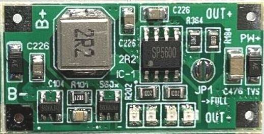
I use it for a lattepanda v.1 uninterruptible ups.There is a strange behaviour to it. When my power supply (led switching power supply 5v, 5a) is plugged in AND is ON everything works as expected (I can unplug it and plug it in a million times), however when the power supply is plugged in to lattepanda BUT I forget to turn it on BEFORE I plug it in, for some reason it interrupts power to the lattepanda. Is there a modification to do to make it work? I’ve tried adding a capacitor (1000mf-2000mf) does not work, a diode does not work, thicken the wire that comes from the power supply (there is no voltage drop). I’m also using a 18650 battery that is rated for 10a. I also used two batteries. I can’t think if something else. Please help 🙁
Hi Haris, You said
“BUT I forget to turn it on BEFORE I plug it in….”
What exactly you forget to turn ON?
My house wall power outlet (sorry for the confusion). If my house wall power outlet is turned OFF and THEN plug the 5v, 5a power adapter to the latte panda’s 5v UPS, then it interrupts power. IF my house wall power outlet is ON then there is no problem pluging and unpluging to the UPS (it does not interrupt power). It is very annoying because if I forget that the wall power outlet is off the lattepanda restarts. Why is it behaving this way?
Haris
Does the problem also happen with loads other than the lattepanda? If no then the issue could be something related to lattepanda, may be an initial high current draw etc. If the problem is happening with all loads then the issue is with the UPS board which can be diagnosed only by testing it practically.
There doesn’t seem to be a quick external solution to this, except connecting an LED at the input side of the UPS which will indicate whether the supply to the UPS is ON initially or not.
Sorry for the poor connection diagram, I’m not an electrician.
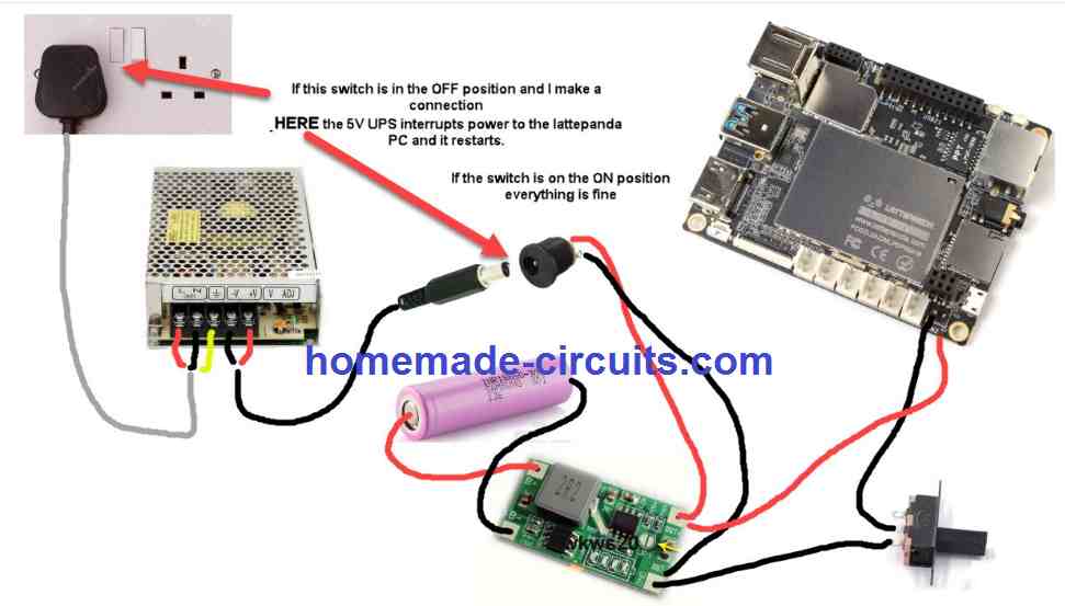
The power supply is a 5v 5 amp LED driver ( I did tried other power supplies and I have the same issue). I tried more powerful batteries same result. I tried the 1k resistor mod that you said, same result.
Thanks for the detailed diagram.
Now it seems much easier to analyze the fault.
You said right, a diode should solve the issue. A diode in series with the socket positive wire should do the trick.
The problem could be happening due to the high value capacitor across the output leads of the SMPS. This capacitor could be causing a momentary drop in the battery voltage and consequently the erratic behavior from the lattepanda….
It is quite strange. Everything works great when the power supply is connected on the lattepanda and the wall outlet is ON. Initial current of 1.8 amps and then it drops down to 1.2 amps. I can plug and unplug the adapter just fine….the problem is that it restarts even when I have the power adapter in my hands! (its not connected to the wall outlet). I just plug the power adapter connector to the lattepanda and it restarts! Will a diode work? I did try many 5v UPS’s from china. Most are up to 1amp max current and they don’t work. However, the eletchsup DD04CVSA was the only one that did support 2a and wasn’t restarting the lattepanda BUT it couldn’t charge my battery while the lattepanda was on (too much current is drawn from the lattepanda).
That sounds strange, it could be due to some low voltage discharge from the UPS board capacitor. I do not know much about lattepanda, so I am not sure what exact “restarting” means, because whenever it is powered it should naturally reboot just like any other computer….unless it has an internal battery.
A diode won’t help, since it will still allow any residual voltage to pass to the lattepanda and cause rebooting. A transistor switch might just help solve the issue.
You can try connecting a 1k resistor across the output leads of the adapter, so that it discharges any residual voltage from the adapter. By the way how is the adapter connected to the UPS board?
A proper wiring diagram across the respective units would help to understand the situation better.
please send spare parts list
It is given in the diagram itself.
Hello
Can I use this automatic micro ups circuit for charging a backup battery, 14.8V 2200 MAH LI ION battery
(Charging current 2A
Discharging current upto 4.4A)
So when power cut it will automatically shift to battery
What is the output voltage and current of this (14.8v battery) ups circuit ?
I want to use this ups circuit output to run a dc motor rated at 12volt 5amp
What modifications needed for this requirement?
Hi, you can use all types of batteries with this circuit, your battery can also be used.
the first one is rated to handle 3 amp and the second one is rated to handle 5 amp
Thank you
Sorry Swagatam, i’ve got an additional question. I want to use the cirquit to charge a backupbattery. Ive got one with a capacity of 2800 mAh and another one of 6800 mAh. Wich of the cirquits do you suggest? Do I have to change/adjust components for these? Thank you!
Hi Yvan, you can try the first circuit with no changes…
I would also recommend you check out the following simpler circuits:
https://www.homemade-circuits.com/usb-automatic-li-ion-battery-charger/
or the last circuit from this article
https://www.homemade-circuits.com/make-6v-4ah-automatic-battery-charger/
Hi Swatagam. Looks nice and I will try this cirquit. A simple question from a rookie in electronics 😉 : In the cirquit “Using a PNP BJT for the above Charger Circuit” I see 2 diodes connected to the modem and also 1 between the tip127/Battery+ and the modem. What types are they? I can’t find this information. THX! Yvan
Hi Yvan, those are ordinary rectifier used for dropping and adjusting the output level for the modem and for the UPS cut-off transition threshold…. you can use a 1N5408 diodes for those.
Hello Swag,
I am unable to get MC78T12 and was using 78012 which is only 1.5 regulator, could that be the reason for my issues i mentioned earlier. Also in my scenario the voltage at pin 3 is not exceeding the voltage at pin 2 in any scenario?
Hello Sumit, 7812 will only give a lower current at the output, it cannot be related to IC malfunction.
If pin#3 voltage is not changing with preset adjustment then either the IC is faulty or the preset is faulty.
check the response at the center lead of the preset by disconnecting it from pin#3, I hope you have connected the preset leads correctly??
Hello Swag,
I have tried with all possible combinations and definitely there is something incorrect. I have more than four op amps and the result is the same, I am now following the third circuit. Also i have gone ahead and created a live simulation on http://www.falstad.com/circuit/circuitjs.html, if you can possibly take sometime and import the simulation from the text file ( https://filetea.me/n3wLxovfIdCTNuQaAArnlDbMQ), you can see where is the disconnect. Please help in checking as i am stuck…
Sumit, unless you are able to do a mind simulation of the circuit, an artificial simulation will be of no use, how are you gong troubleshot the fault in the simulation? Artificial simulation is normally used by the experts to fine tune a mind simulated circuit….
The circuit above has been already tested by me thoroughly, so how can it be wrong, even if it was not tested still the design makes complete sense.
So the first thing you should do is understand how the opamp is configured to work, and how the transistors are supposed to react to the opamp output.
Once you are able to simulate the stages in your mind then troubleshooting will be a matter of minutes and could be done simply with a meter.
If you think something;s wrong please specify it I will be most happy to correct it.
just changing the opamps will not help, you must pick up a meter and check the response of the circuit at various nodes, and verify whether things are correctly working or not as per the specifications.
Hello Swag,
I agree completely with you, the file I have shared has a simulation of your circuit diagram, you can import it to the first falstad link I have shared. The point I am trying to make is when you check the simulation it would clarify few thing :
-Both LEDs will glow simultaneously .
– the circuit can work as expected only when the 10 k pot is at 2.6 and 100k pot at around 26.8k and the input voltage should be around 15 and other combination
might swap LEDs but would not cut off charge …
– I am using it as per the simulation and things seem to work as expected.
– the file I am sharing is an export of the simulation so u just need to import it to see what I am trying to say…
– also I have full respect for you and please don’t think I am doing this for any wrong intentions, only think I am trying to figure out is the correct description..
– you have been kind enough to read through and reply so I have no intentions to challenge your skills. All I am trying to do is update the description for a best suit.
Sumit,
I usually don’t depend on simulators because I know it’s not worth it, because you will never able to reach the actual practical outcome from a simulator’s results, so I will advise you to keep it aside and use it as a secondary tool only.
and moreover this design is too simple and can be diagnosed through visualization
If you really want to achieve success, you should get the parts and make it practically, and diagnose the circuit with a meter in case of a fault, very quickly you will be able to get it up and running.
both LEDs can be never On, you can track the path of the LED current in response to the high and low status of the opamp output, you wil find that only one LED can be ON the other cannot.
for example in the last circuit when the opamp output is high it will allow the green to light but will block the red LED’s path.
but yes there’s a glitch, since the emitter of the PNP is connected with a higher potential than the battery it might force the red LED to light, to rectify this you can isolate the IC 741 circuit’s positive line from the battery and connect it with the emitter of the PNP….except the 10k presets upper lead which can be linked with the battery positive….try this and let me know.
please use the link to download file s000.tinyupload.com/?file_id=71792568399511144314
what is there in it?? if possible please make it directly visible…
Hello sir ,
I need a 11.1v 44oomah li ion battery charger circuit with constant current and constant voltage mode which are modes used in Li ion battery charging.I have a smps of 12v 2amp.I need to give this input.I have to change 12v to 14.5v for battery input HOw could i do this?
please help me on
1) battery charger circuit and this battery has a protection circuit against :sc,over voltage,over current,over discharge,over charge and balance battery charging function
2) How can i create 12v to 14.5v in smps?
Hello Shreyansh,
You can change the voltage of your SMPS if it includes the facility of a preset adjustments, otherwise you may have open the SMPS and do some complex adjustments.
Normally a high current smps will include a preset near the connector output, you can search for this preset around the connector area of the SMPS.
for manual adjustments, you may have to go through the following article:
https://www.homemade-circuits.com/2015/04/how-to-make-variable-smps-driver-circuit.html
Dear Swagatam Majumdar
I’m a big fan of home made circuits, you are doing a great job, really thank you.
Kindly I need your help figuring out, if the attached circuit will work and if there is
any changes that need to be made to make it functional.
Thanks a lot for your reply, I have tried to connect just 2 of the micro charging modules with 2 batteries, while the charger is disconnected the combined output is 8.4v, but once I connect the charger the output is 4.2v and one of the boards out put is near zero v, I came to know that Input – is connected to Out –
and B -, also Out + is connected to B + but not to Input +, so when the charger is connected, B + of one cell is grounded to Input – !
is there anything I can do to resolve that issue ?!
the module has the charger IC TP4056, and overcharge & discharge protection ICs.
Thanks a lot for your reply, the 8.4v is real, I can run a DC motor which draws nearly 200mAh, but higher than that the combined circuits can’t provide power, I believe that’s because of the presence of protection ICs DW01A and S8205A, each battery with the connected TP4056 module can provide 4.2v at 1000mAh max, I connected a 12v 21w car lamp that draws 2.2 Amps, it can pull 1Amp from the battery.
Could an optocoupler be used in isolating ground or combining the circuits ?!
or It’s impossible to do ?!
another question please if use one of these charger modules with a battery pack of 6 Li-on 2200mAh cells & a step up DC converter xl6009 to get 12v 2A ?!
Thanks for your reply, I want to make an advanced Automatic mini UPS so (that I don’t need to worry about overcharge or discharge) for my router it’s 12V 1.5A and some how balance charge the Li-ion cells forming the 11.1v battery pack. The UPS might be in standby mode for long times so not to cause damage to cells, I needed an advanced charger.
this is the schematic of TP4056 Module I have
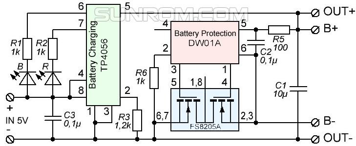
OK, but as you can see the negative supply and the -B are different on the PCB, so your series configuration will work only for the input supply not with the batteries and is not recommended also…better to buy a single 12.6V cell and use a single 12.6V charger.
OK I think got it now, I magnified the image and I could see that the input supplies are taken through the PCB tracks and connected in series, but I am not sure whether the batts can be also connected in that way in back up mode?
without a schematic it will be difficult to figure out the working of the whole configuration?
Can you tell what is your actual need then may I can suggest something?
You can step up 6x2200mAH to 12v 2 amp easily but the charger will not be able to charge a 6x2200mAH pack because the IC is rated to produce only 1000mAh
The output will not combine, rather will show the one which may be higher than the other. The 8V is an inflated value which is shown by the meter due to its high impedance nature, the actual voltage can be confirmed after connecting a load, so if it’s showing 4.2V after connecting the load then that’s fine. You can confirm the same by adding a 1K resistor at the output, this will prevent the meter from showing the inflated value.
I won’t be able to diagnose the IC board connections because I do not remember the pinout functions.
you can refer to the following article and check if it helps
https://www.homemade-circuits.com/2017/04/li-ion-battery-charger-circuit-using-ic.html
Thank you dear Ahmed, I am glad to have you in my website…
yes it should work, the principle is quite similar to what I have explained in this post
https://www.homemade-circuits.com/2013/03/simple-dc-ups-circuit-for-modemrouter.html
HI sir,
In my Li ion battery pack is of 11.1v and 8800mah. There is a Battery management chip:
1. Battery Charge Cutoff Voltage: 12.6V 2. Battery Discharge Cutoff Voltage: 8.25V 3. Battery Charge & Discharge Mode Integrated 4. BMS Passive Protection Function: Overcharge Protection, Over discharge Protection, Over Current Protection, Temperature Protection, Balanced Function
5. Battery Inner Resistance: <=33.75mohm 6. Continuous Discharge Current: 3A 7. Maximum Discharge Current: 5A
I have a smps of 12v 2a can i apply this supply directly to this battery for charging?
And for automatic switchover between battery and smps supply I have used relay.Is this possible to give smps supply directly to battery?
Thanks sir,
As I said that there is a bms chip with 11.1v 8800mah li ion battery pack, so there is any need to charge this battery with cc and cv mode ?
If needed then how can i make? please ,sir help me.
CC/CV input will not be required if a special controller IC is used
Hi Sham,
A 12V supply will not charge your 12.6V battery, even if you keep it connected forever….you will have to increase the SMPS output upto 12.6V, or at least 12.5V.
Next, you must have an automatic cut-off system between the SMPS and the battery so that the SMPS supply is instantly cut off as soon as the 12.6V level is reached.
If you satisfy the above two conditions then definitely you can connect the mentioned SMPS with the battery.
Having said that, a 2amp rate will take more ta 10 hours to charge your 8 AH battery…better to go for a 5amp smps.
hey, that's what i looking for!! thx for sharing this schematic.
how i modified that since i just need 2amp max out?
replace the 0.4ohm resistor with the following
R = 0.6/200(0.2)
= 3 ohm 1/4 watt
ok thx, i have PS 15v 3amp. n i need to limit the charging current about 100/200mA. what should i do to modified the circuit?
Hello Swag,
Unfortunately tired with the suggestions, its the same. adding a zener just did a change that the green led is on simultaneously with the red (upper limit). lower limit is still an issue, i also tried adding a 600k pot for varied range but no luck. I am thinking to use the second circuit with current eliminating resistor as 0.82 ohms, my battery is 12v 7.2ah sla battery , would it be a good idea to use that design? also would you have any recommendation for taking dual outputs 12v and 5 v @.5ooma (my plan is to regulate the 12v to 5v by 7805)? Thanking you for all your valuable inputs and support.
Hi Sumit, the green LED and the red LED are connected with opposite modes so they can never turn ON simultaneously.
Green LED will be ON when pin6 is 0V, when pin#6 is 0V red will be obviously OFF, similarly when pin#6 is high red will turn ON, and green will be shut OFF because green will now have both its ends at positive.
you must investigate why your circuit is not working using a meter.
basically when pin#3 is higher than pin#2 voltage level, pin#6 will be high, and conversely when pin#3 voltage is lower than pin#2 then pin#6 will become 0V…so please check whether these things are taking place or not, you can trace the fault within minutes.
Sometimes if the IC is not good gives rise to unnatural results….
you can try any of the opamp based designs from this websire all will work… but before that you must make an effort to understated and grasp the functioning of the opamp and troubleshoot the present design.
Hello Swag,
Thank you once again for the explanation i think i have found the issue, can you please confirm if there is a 10k resistor between the 10k pot variable pin and 741 pin 3? If Yes than i think i have missed this particular component in the design.
Hi Sumit, yes it is there but that cannot be the issue, and its presence is not crucial.
you must check the voltage at pin#3 with reference to pin#2 while adjusting the preset.
as soon as pin#3 voltage goes higher then the pin#2 reference voltage (4.7V), pin#6 voltage should get to the supply level from its previous 0V…makes sure to keep the zener connected at pin#6 as advised earlier, and check the pin#6 volatge after the zener.
preferably connect the LED in the following positions:
https://www.homemade-circuits.com/2012/07/make-6v-4ah-automatic-battery-charger.html
and keep the feedback link disconnected while confirming the above….
you can easily extract 5V from 12v using a 7805 circuit
Hi, you can adjust the 0.4 ohm resistor value to limit the output at 2 amp, using the following formula
R = 0.6/2 = 0.3 ohms
wattage = 0.6 x 2 = 1.2 watts
Hello Swag,
Thank you so much for your efforts in helping with such circuit, i have made the first circuit, my loads are two routers (12v 0.5amp and 5v 0.5 amp), I planed to use an additional 7805 at the output to reduce the power to 5v 0.5amp. My battery is 12v 7.2 AH. I have below question if you can please help :-
– I am unable to set the lower threshold, if I reduce the input power to 11.0 v and use the 100k var nothing happens the green led is always on ? i can only set it by the 10k pot but then i loose the overcharge cutover.
– Is Green LED (+) contact is connected to the positive terminal before the 1N5408 ?? because if i connect is towards the battery side the circuit does not behave at all ?
Hello Sumit, it could be happening due to leakage voltage from the IC output, you can try connecting a 3V zener diode in between the pin#6 of the IC and the rest of the connections, meaning let the connections at pin#6 be after the zener diode and not directly with pin#6, as done in the following article
https://www.homemade-circuits.com/2012/07/make-6v-4ah-automatic-battery-charger.html
the 100K preset can be connected before the zener or after zener, it is not crucial.
please note that you must first adjust the 10K preset fo the upper limit ensuring that the feedback 100K disconnected udring the adjustment, once this is done then you can connect back the 100K link and proceed with the lower threshold adjustments.
preferably you can replace the 100K with a 470K for getting a wider range of adjustment.
green led can be connected with the positive rail of the IC pin
Thank you Swag let me try it, can i use a 3.6v zener instead ? also when i am setting the thresholds the loads and battery should all be disconnected is that rght??
Hi Sumit, a 3.6V zener will be OK, and yes there shouldn’t be any battery or load connected while setting up the design….
Hello, I was so exciting about your site and as feedback send you PCB

1.
2.
Thanks Ehsan, I appreciate your effort, I am sure the readers will like it…
Hello Swagatam ..
I'm really excited in your projects..
I want you to help me and ask you some questions :
i have 13.8v 3amps smps ,12v 4.5ah battery and modem&router(1.5A load).
The question is when i tried to test changeover circuit that you posted the battery discharges and iam really checked the current flews from the battery but most be charging when the mains pw is on ,
I tried connect the smps to battery directly (dioades exist) ok its charge but when loading at 1.5A both smps& battery supplied the load output. .
So how can i make automatic ups to remains my network on and battery charges correctly when main ON ?
Hello Ahmed,
sorry, I could not understand your question correctly, because I am not sure how you checked the situation and to which circuit diagram you are referring to??
If it's the first circuit which is causing the problem, you can simply add a diode just at the right side of thee 1K base resistor of the TIP122 this will stop the battery from self discharging when the mains fails….if possible I'll update the diagram soon with the correction