I have been put forth with this question many times in this blog, how do we add a changeover selector switch for automatically toggling of an inverter when AC mains is present and vice versa.
And also the system must enable automatic switching of the battery charger such that when AC mains is present the inverter battery gets charged and when AC mains fails, the battery gets connected with the inverter for supplying AC to the load.
Circuit Objective
The configuration should be such that everything takes place automatically and the appliances are never switched OFF, just reverted from inverter AC to Mains AC and vice versa during mains power failures and restorations.
So here I am with a couple of simple yet very efficient little relay assembly module which will do all the above functions without letting you know about the implementations, everything is done automatically, silently and with great fluency.
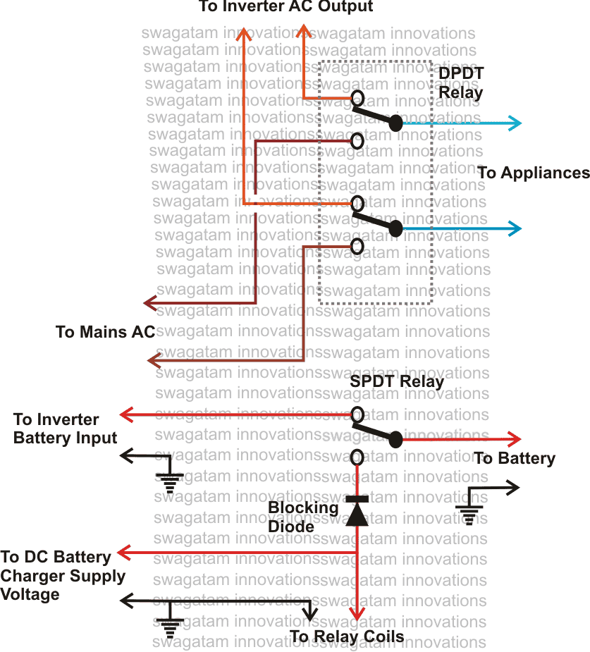
1) Inverter Battery Changeover
Looking at the diagram we can see that the unit requires two relays, however one of them is a DPDT relay while the other one is an ordinary SPDT relay.
The shown position of the relays are in the N/C directions, meaning the relays are not powered, which will obviously be in the absence of the mains AC input.
At this position if we look at the DPDT relay, we find it to be connecting the inverter AC output to the appliances through its N/C contacts.
The lower SPDT relay is also in a deactivated position and is shown to be connecting the battery with the inverter so that the inverter remains operative.
Now let's assume that AC mains is restored, this will instantly power the battery charger which now becomes operative and supplies power to the relay coil.
The relays instantly become active and switch from N/C to N/O, which initiates the following actions:
The battery charger gets connected with the battery and the battery starts charging.
The battery gets cut OFF from the inverter and therefore the inverter becomes inactive and stops functioning.
The connected appliances are instantly diverted from the inverter AC to the mains AC within a split second such that the appliances doesn't even blink, giving an impression that nothing had happened and the are kept operative continuously without any interruptions.
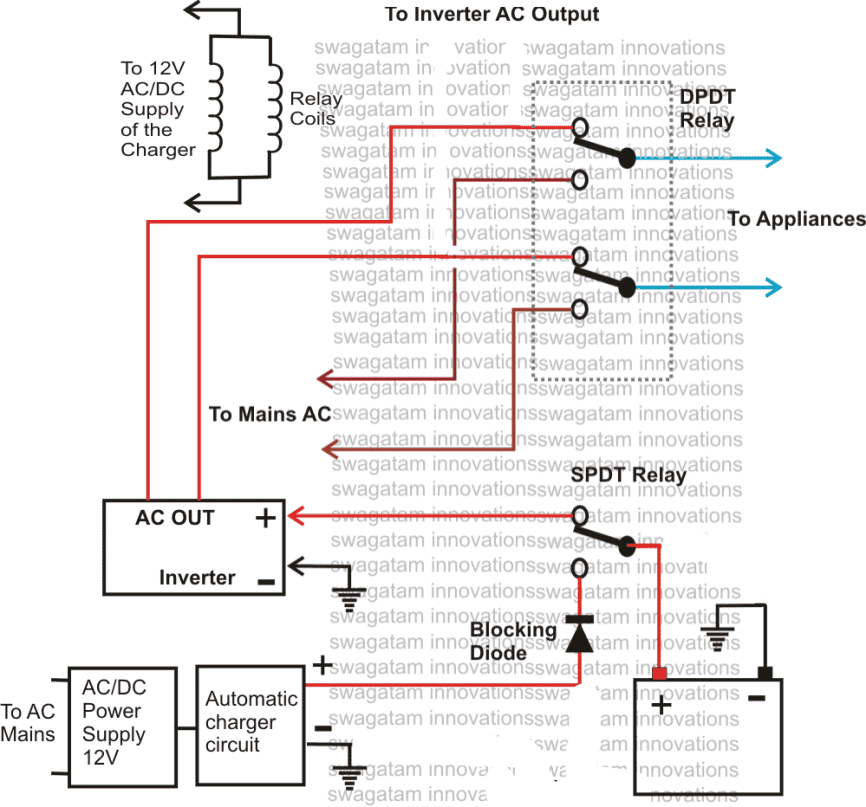
A comprehensive version of the above can be witnessed below:
2) 10KVA Solar-Grid Inverter Changeover Circuit with Low Battery Protection
In the second concept below I have explained how to build a 10kva solar grid inverter changeover circuit which also includes a low battery protection feature. The idea was requested by Mr. Chandan Parashar.
Circuit Objectives and Requirements
- I have a solar panel system with 24 Panels of 24V and 250W connected to generate a output of 192V, 6000W and 24A. It is connected to 10KVA, 180V inverter which delivers the output to drive my appliances during daytime. During night the appliances and inverter run on grid supply.
- I request you to kindly design a circuit which will change the inverter input from grid to solar power once panel start generating the power and should again revert the input from solar to grid once darkness falls and solar power generation falls.
- Kindly design another circuit which will sense the batter.
- I request you to kindly make a circuit which will sense that battery is getting discharged below certain threshold value say 180V (esp during rainy season) and should switch the input from solar to grid even though some amount of solar power is being generated.
Designing the Circuit
The 10kva solar/grid automatic inverter changeover circuit with low battery protection which is requested above can be built using the concept presented in the following figure:
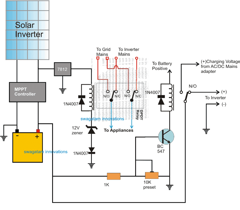
In this design which may be slightly different to the requested one, we can see a battery being charged by a solar panel though an MPPT controller circuit.
The solar MPPT controller charges the battery and also operates a connected inverter through an SPDT relay for facilitating the user with a free electricity supply during day time.
This SPDT relay shown at the extreme right side monitors the over-discharge condition or the low voltage situation of the battery and disconnects the inverter and the load from the battery whenever it reaches the lower threshold.
The low voltage situation could mostly take place during night when there's no solar supply available, and therefore N/C of the SPDT relay is linked with a AC/DC adapter supply source so that in an event of a low battery during night the battery could be charged for the time being through the mains supply.
A DPDT relay can be also witnessed attached with the solar panel, and this relay takes care of the mains supply changeover for the appliances.
During day time when the solar supply is present, the DPDT activates and connects the appliances with the inverter supply, while at night it reverts the supply to grid supply in order to save the battery for a mains failure back up situation.
UPS Relay Changeover Circuit
The next concept makes an attempt to create a simple relay changeover circuit with zero crossing detector which may be used in inverter or UPS changeover applications.
This could be used for switching-over the output from AC mains to inverter mains during inappropriate voltage conditions. The idea was requested by Mr. Deepak.
Technical Specifications
I am looking for circuit comprising of the comparator (LM 324) to drive a relay. The objective of this circuit is to:
1. Sense AC supply and switch relay 'ON' when voltage is in between 180-250V.
2. Relay should turned 'ON' after 5 seconds
3. Relay should turned 'ON' after zero voltage detection of supplied AC (Zero voltage detector). This is to minimize arching in the relay contacts.
4. Finally and most importantly, the relay switchover time should be less than 5 ms as a normal off-line UPS does.
5. LED indicator to indicate the state of relay.
The above functionality can be found in UPS circuit which is bit complex to understanding since UPS has many other functional circuit beside this. So am looking for a separate simpler circuit which only works as mentioned above. Kindly help me to build the circuit.
Component available and other details:
AC mains = 220V
Battery = 12 V
Comparator = LM 324 or something similar
Transistor = BC 548 or BC 547
All type of Zener are available
All types of resistor are available
Thanks and Best regards,
Deepak
The Design
Referring to the simple UPS relay changeover circuit, the functioning of the various stages may be understood as follows:
T1 forms the sole zero detector component and triggers only when the AC mains half cycles are near to crossover points that's either below 0.6V or above -0.6V.
The AC half cycles are basically extracted from the bridge output and applied to the base of T1.
A1 and A2 are arranged as comparators for detecting the lower mains voltage threshold and the higher mains threshold respectively.
Under normal voltage conditions the outputs of A1 and A2 produce a low logic keeping T2 switched Off and T3 switched ON. This allows the relay to remain switched ON powering the connected appliances through mains voltage.
P1 is set such that voltage at the inverting input of A1 becomes just lower that the non-inverting input set by R2/R3, in case the mains voltage falls below the specified 180V.
When this happens, the output of A1 reverts from low to high triggering the relay driver stage and switching off the relay for the intended changeover from mains to inverter mode.
However this becomes possible only when the R2/R3 network receives the required positive potential from T1 which in turn takes place only during the zero crossings of the AC signals.
R4 makes sure that A1 does not stutter at the threshold point when the mains voltage goes below 180V or the set mark.
A2 is identically configured as A1, but it's positioned for detecting the higher cut-of limit of the mains voltage which is 250V.
Again the relay switch over implementation is executed only during the zero crossings of the mains AC with the help of T1.
Here R8 does the momentary latching job for ensuring a smooth transition of the switching.
C2 and C3 provides the required time lag before T2 can conduct fully and switch ON the relay. The values may be appropriately selected for achieving the desired delay lengths.
Circuit Diagram
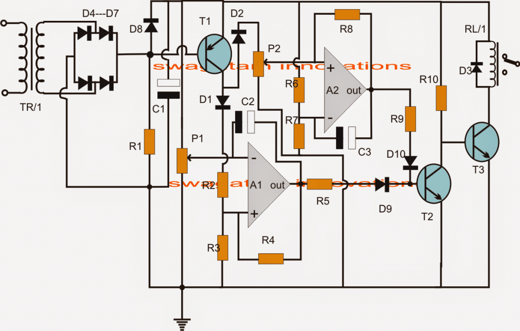
Parts list for the zero crossing UPS relay changeover circuit
- R1 = 1k
- R2,R3,R4,R6,R7,R8 = 100K
- P1,P2 = 10K PRESET
- R5, R9 = 10K
- D3,D4---D10 = 1N4007
- C1,C2 = 1000uF/25V
- T1 = BC557
- T2 =BC547
- Z1= 3V ZENER
- A1/A2 = 1/2 IC LM324
- RL/1 = 12V, SPSDT RELAY
- TR/1 = 0-12V STEP DOWN TRASFORMER


Questions & Answers
Please draw an automatic ac dc changeover circuit
I have been looking for an automatic transfer switch for a 2 kW solar system, which switches a load of max 3kVA from inverter to mains voltage once the batteries are low, and re-connects the inverter once the batteries are fully charged, thus giving the battery bank a healthy charge cycle before re-engaging. I have found the ideal switch on ebay
A friend suspected, that because of the very short switching time the magnetic field of a motor could not drop sufficiently and, should the inverter and mains phases not be in sequence, the motor could be damaged due to back rmf voltages. This does not mean much to me. Therefore, could you pleae enlighten me and tell me wheteher my friend’s concerns are justified? mmany thanks, Volker
Yes, that’s correct. The phase sequence should be perfectly matched between the inverter AC output and the mains AC output
I think that I have been looking the wrong type of changeover, the following is what I need to do.
I have a chick egg incubator which has 2 separate circuits.
(1) 220v AC input which powers 220v AC heater and fan.
(2) 12v DC input which powers 12v DC heater and fan.
So the incubator can use either 220v AC Mains supply or 12v DC supply from a 12v battery.
Normally I run the incubator using the 220v but during one of numerous mains power outages I switch off the mains and switch on the 12v supply.
The problem in having to manually switch over from 220v to 12v .
Therefore I am looking for a automatic changeover that senses when the 220v goes off and switches it to the 12v supply and can then switch back to the 220v when the mains supply comes back on.
Can you kindly assist how to do this.
Thanks John
Sure, I can help.
You can try the following DPDT relay diagram, it will do the job for you.
The positive of the 12V which is supplied to the relay coil must go to the cathode of the 1N4007 diode and the 12V negative should go to the anode of the diode.
Good Afternoon Many thanks I will make this.
I bought the 1N4007 Diode but the relays found at the electronics shop are abit different design, they have the pins layout in a circle and plug into a base socket that then clips into the DNS rail.
I can get :-
11 pin with 220v coil
and
8 pin with 12vdc coil.
Please confirm these can work for me.
They look similar to the following
https://www.amazon.co.uk/General-Purpose-LY2N-J-HH62P-L-JQX-13F/dp/B09X1BSF6B/ref=sr_1_7?keywords=12v+dpdt+relay&qid=1660651570&sr=8-7
Thanks John
Yes this relay will work. In fact any 12V relay will work which includes two sets of pole, N/C and N/O contacts. A 12V version should be more preferable, since it can work with a 12V DC which is easier to configure than 220V AC.
Thank you I have now bought relays
I have a query regarding the position of the 1N4007 Diode
You said :- The positive of the 12V which is supplied to the relay coil must go to the cathode of the 1N4007 diode and the 12V negative should go to the anode of the diode.
Can you please indicate on the diagram the position where to make the connection ?
Many many thanks.
John
You are welcome John! Inside the relay you will see that it has a coil whose ends terminate to a couple external terminals. You will have to connect the diodes across these terminals. You can connect the diode across these terminals any way round, and then make sure that the positive supply goes to the cathode terminal and the negative supply goes to the anode terminal.
Good Afternoon
I have bought 2 relays 1 x 220v, 1 x 12Vdc both have 11 pins
I have identified the pins as
1 Power in
2 Coil
3 N/O
4 N/C
5 N/O
6 Common
7 N/C
8 N/C
9 N/O
10 Coil
11 Power In
I understand you regarding the diode – should go between pins 2 & 10
But following your diagram I am confused ?
I wire up the 220V relay
I wire up the 12 Vdc relay
But I do not know if and how these 2 relays are interconnected ?
If they are not interconnected how will it know which supply 220v or 12v is live ?
Thanks John
Hi, you must use a single 12V relay, a 220V relay is absolutely not required. Why do you want to use a relay with a 220V coil??
So please purchase a 12V DPDT relay which must have only 8 pins in all.
2 for the coils, 2 for the poles (common), and 4 for the respective N/C and N/O contacts.
Thanks for your reply, I am now totally confused, I had thought that as I am wanting to automatically switch between 220v and 12vdc supply. Hence I bought the 2 relays.
You say to purchase a 12V DPDT relay which must have only 8 pins.
I think that I am correct to think that the power IN should go to pins 1 and 11 ? but how can I be connecting both 220v and 12vdc together to pins 1 and 11, surely this will blow up.
Also can 220v be connected to the relay with a 12vdc coil ?
You say the relay must have only 8 pins, so I cannot use the 11pin 12vdc coil that I bought ?
I am sorry for keep bothering you.
Thanks John
For a 12V relay, the coil is supposed to be operated through 12V DC, not through a 220V. This 12V DC is derived from a 12V AC/DC power supply unit
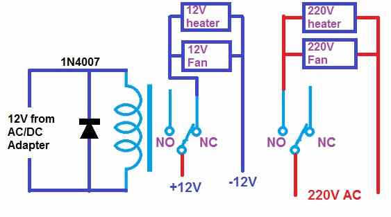
The switching of the 12V DC and the 220V AC is done separately by the two sets of N/O and N/C contacts.
Please refer to my previous diagram again. It clearly shows how the two sets of contacts are used for switching the 12V DC and the 220V AC separately for the separate heaters and fans, as required by you.
Let me know if you have more doubts.
Easy Automatic Inverter/Mains AC Changeover Circuits
Good Morning Swagatam very interested in this type.
I have a chicken egg incubator but the mains power is always going on loadshedding, so I need to be able to automatically change from Mains to 12V inverter power when the Mains goes off.
I note the unit requires two relays, however one of them is a DPDT relay while the other one is an ordinary SPDT relay. I have looked online for these relays but there are so many different types of these relays. Can you please advise which DPDT and SPDT relays to buy.
Many Thanks
John
Thank you John,
Basically an SPDT relay will have 5 pins (two for the coils), and a DPDT relay will have 8 pins (two for coils). You an use any 10 amp relay such as the following which is a DPDT relay:
You can use the same type of relay for SPDT also by using one set of pinouts and keeping the other set unconnected.
Good Afternoon
(1) You say that I can use any DPDT and SPDT 10amp relays but when I look for on the internet they are 10amp but also refer coils of differing voltages, this is confusing me ?
(2) The diagrams shows reference to COILS ?
Thanks
John
Hi, All relays require a coil voltage to operate. This coil voltage rating is selected according to the supply voltage of the circuit. If 12V supply is available then the relay coil must be also rated at 12V. If the supply voltage is 5V, then the relay coil must be rated at 5V and so on.
In the diagram, the relay coils are activated using the DC output from the battery charger. If the battery charger is for charging 12V battery, then its max output will be 14.1V. So in this case the relay coil voltage can be 12V. Alternatively if you don’t want to use the battery charger DC for activating the relay coils you an use a separate 12V AC to DC adapter and use its output DC to activate the relays.
Thanks for your help
Sir will the no of Spdt relay connected to + of inverter card make reverse current flow in dpdt relay of grid mains connected to no
Dweep, no that can never happen, because all the relay contacts are isolated from each other
Dear Sir, is this process going to work for such;
remote communication site powered by diesel generator. To save cost and time, generator is running and powered the equipment, at same time it also charging the battery. Once battery fully charge, it automatically cuts off generator and equipment now is powered by battery for period of time until it cuts off again from battery and switch on to generator with battery now on its charging status.
Hello Songat, yes the mentioned process is possible using a changeover relay.
Hello Sir, I may require a schematic wiring diagram in regards to my previous query if possible.
Thanks
Hello Songat, switching ON a generator is a relatively complex process, I do not have a suitable idea for a generator starter.
Noted with thanks, am about to figure out something. I will give it a trial.
????????????
Cheers
Sure, no problem….
A google search brought me here while looking for a solution. Thank you for taking the time to share this!
I’d appreciate your thoughts on my idea.
UPS units are expensive per unit of capacity/runtime. I have a 120VAC UPS protecting my home LAN where each protected device uses a 12VDC power supply – the same as my UPS battery. Some of the runtime is wasted on the inverter/rectifier. Is it worth figuring something out or should I just buy a bigger UPS? I can’t find anything that can concurrently maintain a battery and support a 12VDC load during normal operation, so failover must be switched.
My idea: Get a large capacity 12V battery, a smart/trickle charger, 12VDC relay, and a large AC/DC 12V power supply. Relay coil connects to the power supply. Relay contacts switch the load between (NO) the power supply output and (NC) the battery. Add a buck converter for 5V devices. Add low battery protection as you described above.
Benefit: 12VDC UPS capacity that is greater, less expensive, and more efficient.
Thoughts?
Your idea looks perfect and efficient for the specified application. Therefore you can perhaps go ahead with this idea.
More related stuff can be found in this article:
3 Simple DC UPS Circuits for Modem/Router
My generator can’t carry my air conditioners at home, so when ever the general public power outage, and I switch to generator. I want the air conditioners to automatically go off. Pls sir what relay or device should I use.
Hi Nelson, You can use a small 12V AC to DC adapter, and connect a 12V relay with it. The relay will switch ON and OFF in response to the AC power input condition. You can use the contacts of this relay to switch your air conditioner accordingly.
Hi Sir, am busy with a DIY power back up system for my small house & i can use your help… am using government electricity and in most cases there’s load Shedding. so i have created a back up system, i want it to automatically switch on when there’s load shedding & automatically Switch Off when the main Power Comes back.. what kind of Switch or Relay can i use?
hi Godfrey, it seems you are trying to make an offline UPS system.
You can do it by using any ordinary set of relays whose contact AMP ratings are appropriately matched with the load AMPs.
so if your load is 20 watts then the contact rating must be also rated at least 1.5 times above this value, and no way less.
Sir, I simulated the suggested circuit by adding a DPDT relay connected to mains.
If power fails relay trips and power available relay poles goes to NO.
Out of 4 positions only 2 are working as expected. Other 2 positions inverts the lamp condition.
I have attached the picture left hand side is power available condition and right hand condition is power failure condition
During power failure relay changes its contacts, also added DPDT relay also changes over, switch remains the same.
Attached picture with all conditions are added.
Sir pls review and suggest me some ideas.
Kumaran, for a four position it can be difficult to suggest a solution, I tried to solve it for the 2 way switch as per your initial schematic.
The suggested DPDT in my diagram is a switch, it is not a relay. It has to be toggled manually to change the state of the lamp
Thank you sir, for all your suggestions. I want to keep this circuit fully automatic during power off
without any human intervention. Thanks
You are welcome Kumaran, I assume that the requirement is, the lamp to be operated with the SPDT relay from home, and also manually using the two switch, regardless of the mains/inverter relay position. So if the lamp is ON, it has to stay ON regardless of the mains/inverter relay position.
If this switched ON lamp needs to be switched OFF then it could be done using home automation SPDT or manually using the two way switch? Same will be true, if the lamp is OFF and needs to be switched ON.
If the above is correct, you can modify the previous original diagram by disconnecting the pin30 of the home SPDT relay, and connect it to the neutral line, and disconnect the lamp from the neutral and connect it with the pin30 of the mains/inverter relay
Sir, Your said logic is exactly the same what I wanted. But even if I modify the neutral line, when the power is lost home automation relay when in ON position will always go to OFF due to power failure, thereby changing the state of lamp.
Sir attached pls find the logic diagram.

Sir, is it possible to add some discrete components circuit (1bit non volatile memory) to hold the state of relay until the UPS takes over?. My UPS take over time is approx. 35secs
Please suggest.
Good Day Sir, I finally powered my Home automation relay board through UPS. Lot of rewiring, better than implementing new circuit.
Kumaran, in that case there’s only one solution, that is to operate the relay with a chargeable battery, and switch.
relay requires significant power to hold which can be delivered only with a battery. A couple of li-ion cells in series will do the job.
Good Day Mr. Swagatam,
Sir, I have below circuit employed at my home.
Automatic changeover relay idea is from your website and works very well.
Since I used 2 way wiring between relay and manual switch, during power failure I face problem of Lamp turning On or Off depending on switch position.
Out of 4 positions of two way switches 2 are working fine and other 2 are working opposite.
Please help me with some circuits preferably using relays and/or switches to overcome this problem during power failure.
UPS takes over without any issues but SPDT relay loses power from mains, changing contacts thereby switching the lamp.
Since the space is limited, kindly give me some idea.
Hello Kumaran, Please specify the purpose of the two way switch, since there’s only one lamp involved in the circuit?
Sir, two way switch and spdt relay are connected in staircase wiring to operate the lamp from home automation system and also by local two way switch. During power failure as spdt relay loses power, lamp is toggled. I want to keep the state of lamp even after power failure. Pls help
Kumaran, the state of the lamp will depend on the manual switch position. You should remove the manual two way switch to ensure that the lamp always lights up when the mains fails.
Sir, relay and manual switch is staircase wired to operate the lamp both from home automation and also local manual switch. If I remove manual switch, local control of lamp will be disturbed, and to operate a lamp people at home will be looking for a mobile phone to operate home automation relay. Sir pls help if I can add a relay or a switch (DPDT,SPDT) somewhere to keep the state of lamp even after mains power failure.
Kumaran, you can try the following DPDT switch arrangement, it should solve the problem for you:
Good day sir, thanks for your article, I designed a change over system for my inverter, everything works well, I used rectified DC to power the relay coils, but my challenge is when ever mains comes in and the relay switches state I notice AC voltage on my battery terminals and sometimes causes small shocks, plus what’s the reason. thanks
Daniel, all the circuits presented use an AC to DC isolated adapter, so there shouldn’t be any AC leakage into the relay circuit. Make sure your AC/DC adapter charger is perfectly isolated from the AC mains.
hi there can you make design for me for automatic change over for battery charger for example i have battery charger of 42 volts dc and i have 2 seperate battery 36 volts when the 1st battery is full it will automatic to charge the second battery and vice versa thank you.
Hi, You can try the last concept explained in the following article:
https://www.homemade-circuits.com/automatic-dual-battery-charger-with/