In this article I have explained a simple overload cut off circuit for safeguarding heavy mains operated machines such as a lathe machine. The idea was requested by Mr. Howard Dean.
Technical Specifications
May I first say I have very little knowledge of electronics although I could follow a simple diagram.
I operate a small Chinese lathe for hobby machining (making model steam engines) but occasionally the system is overloaded and a 3 amp fuse blows, I appreciate this fuse is there to protect the motor.
Would it be possible to replace this fuse with a cut-out switch rather like a domestic unit so that I don't have to change fuses.
The problem does not occur often but when it does it is a damned nuisance getting to the fuse as it is situated at the back of the lathe which I have to haul around. A bit much at 75.
Any assistance would be appreciated.
Many thanks.
Howard Dean
The Design
I have already discussed one simple overload protector circuit design in one of my previous posts, the same can be utilized for the proposed lathe machine overload cut off application.
Referring to the circuit diagram below, we can identify the following main stages in it:
An opto coupler stage driven by a bridge rectifier
and a latching relay circuit stage coupled with the above opto coupler stage.
Circuit Diagram
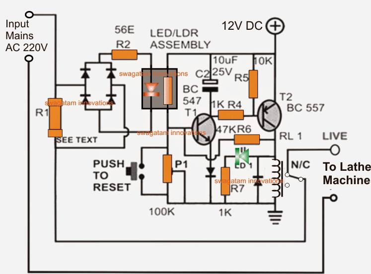
The AC mains is supplied at the indicated left side input, which is passed on to the load via a load sensing resistor R1 and the associated cut off relay's N/C contacts, N/C stands for normally closed, meaning the contacts are connected across this point while the relay is in a deactivated state.
R1 is suitably calculated such that a potential difference sufficient enough to trigger the opto LED develops across it whenever an overload exceeding the unsafe zone is reached.
The overload cut off operation is executed in the following manner:
For so long as the load is within the the normal range of consumption, the voltage across R1 stays low, keeping the opto LED disabled.
However in case of a short circuit or an overload at the output, which may be in a lathe machine for the proposed design, the voltage across R1 shoots and becomes sufficiently high so as to switch ON the opto LED instantly.
The opto LED in turn illuminates the associated LDR sealed inside the light proof enclosure causing its resistance to drop significantly.
This drop in the the LDR voltage allows a biasing current to the base of R1 which along with T2 instantly flips into a latching mode switching ON the relay.
The relay contacts respond to this and deliver the required changeover cutting off the AC line to the load or the lathe machine.
The circuit stays latched and frozen until the power to the circuit is switched OFF and switched ON resetting the relay in its initial form. Alternatively the shown push button may also be pressed for the same.
The green LED indicates the latched mode of the overload protector circuit and also confirms a power off to the output load.
The opto coupler is a homemade device, the construction details may be studied in the following article:
https://www.homemade-circuits.com/2011/12/how-to-build-simple-electronic.html
Using an LED/LDR combination for the opto coupler appears to be much reliable in its operations, however a conventional LED/transistor opto (such as a 4n35 etc) can also be tried instead, and might just work as reliably, it could be a matter of some experimentation.
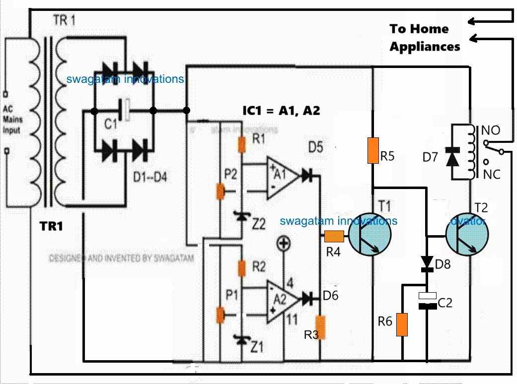
Using an Opto-coupler
The above design can be also built using an opto-coupler instead of an LED/LDR assembly, as shown below:

Current Limit Formula
R1 may be calculated using the following formula:
R1 = LED forward voltage / overload current (in amps)
P1 s for adjusting the sensitivity of the circuit.

Questions & Answers
I tested the above circuit with a few AC bulbs. I used .5ohm R1. When I switch on one bulb relay immediately operates. To troubleshoot I removed the Optocoupler cap and Set the P1 to Zero ohm. After this, I switched on the 250W Bulb and noticed that a Red led flicked momentarily which triggers the circuit immediately and the relay got ON. I tried to fix this issue by adjusting P1 so that the circuit doesn’t trigger the Relay immediately i.e. on one flick of RED LED but P1 is not at all effective in adjusting the sensitivity of the circuit. Can you please guide me in fixing the above issue as I need this circuit for protecting my motor? My motor takes 7 amps while starting and after 3-4 seconds current reduces to 2amps.
P1 is not for producing a delay effect, it will only control the sensitivity of the circuit, meaning at what current level the relay will operate.
P1 is 100% effective in controlling the sensitivity of the circuit provided the opto-coupler uses an LDR.
If you set P1 to zero ohms then T1 will be completely disabled and turned OFF so how can the relay latch??? That’s impossible.
First you must ensure your transistor-latch circuit is working correctly, and, make sure the LED/LDR opto is fully covered inside a light-proof box.
If you want to introduce a delay effect on the circuit you can connect a 100uF/25V capacitor across the base of T1 and ground.
To learn more about the latch circuit operation please refer to the following post:
How to make a Transistor Latch Circuit
Thank you sir for your reply. My problem is red LED flicker once in the optocoupler when I switch on 200W bulb which is taking only .5 to .6Amps. only This flickering activates LDR and Relay operates before the desired cutoff current level is reached.
Secondly, you are right that “setting P1 to zero ohms then T1 will be completely disabled and turned OFF so how can the relay latch???” I set it P1 zero to bypass the relay trigger circuit so that I can see what is happening to my red LED in the optocoupler when switching on AC load i.e. single bulb.
If possible can you guide me on why the RED LED flickers when switching ON AC Load of 200W bulb? Secondly, how does this circuit handle starting high current of the Motor which reduces once the motor is in running condition?
OK, understood now. The LED flickers once initially due to switch-ON current spike. You can try increasing the R2 value to 220 ohms or 330 ohms and connect a 100uF/25V capacitor right across the LED terminals. The 100uF will absorb the initial spike and stop the LED from flickering. See if this helps or not. Make sure the LED/LDR assembly is kept inside an opaque light-proof enclosure.
Thank you sir for your reply. Could you please reply to my second question also i.e. Can this circuit handle the high starting current of the Motor i.e. 7 Amps which reduces to 1.5Amps after 5 seconds i.e when the motor is in running condition? I want to set the cutoff current to 1.7-2 Amps so that the motor doesn’t burn. Can I do that with this circuit?
The circuit can handle 7 amps, but that will depend on the relay contacts rating. I would recommend you to use a 30 amp relay, and replace the relay driver transistor BC557 with 2N2907 transistor. The 100uF capacitor across the LED will ensure that during the short initial period when the load consumes 7 amp current the LED remains shut off. To make sure the 100uF normally remains discharged, you can also include a 10K resistor parallel to the LED. Meaning, add a 10K and a 100uF capacitor both parallel with the LED.
Thanks a lot but please what is the actual value for R2 ?. Because I am seeing (56E) please reply
it is not critical, use any value below 100 ohms and above 20 ohms